Note: Descriptions are shown in the official language in which they were submitted.
WO 2021/034732
PCT/US2020/046585
1
PATENT COOPERATION TREATY
FIREARM HOLSTER
Inventors: Scott Evans and Nicholas Tomczak
BACKGROUND OF THE INVENTION
I. Cross Reference to Related Applications
[0001] This application claims priority to U.S. Provisional
Patent Application No. 62/888,155,
filed August 16, 2019, the entirety of which is incorporated by reference as
if fully disclosed
herein.
Filed of the invention
[0002] The present invention relates generally to holsters
for handguns having a retention
mechanism associated therewith for preventing unauthorized withdrawal of the
weapon from the
holster and, more particularly, to an improved retention mechanism which
allows for rapid
deployment of the weapon from the holster pocket by the user when desired, but
prevents
unauthorized, accidental or inadvertent removal of the weapon from the
holster.
General Background
[0003] Inadvertent, accidental, and even unauthorized
removal of a weapon from a holster is
a common problem faced by law enforcement personnel, military personnel and
other tactical users
of holstered weapons. To be effective, a holster must address two major
concerns, namely, (1)
security of the weapon at all times, and (2) allowing the authorized user
access and means for the
rapid deployment of the weapon when desired. There is therefore a need for
effectively carrying a
weapon in a holster and for rapidly deploying such weapon when needed. There
is also a need to
effectively prevent accidental, inadvertent, or unauthorized withdrawal of the
weapon from a
CA 03147475 2022-2-9
WO 2021/034732 PCT/US2020/046585
2
holster such as when the authorized user is running, maneuvering, or otherwise
engaging the
enemy or an assailant.
[0004] The prior art discloses a wide variety of different
mechanisms to prevent inadvertent
withdrawal of a weapon from a holster. Prior art constructions for the most
part are characterized
by complicated and cumbersome mechanisms which are inconvenient, awkward and
difficult to
manipulate and operate to achieve rapid deployment of the weapon from the
holster, and such
mechanisms can suffer from substantial wear and tear during use. Although such
security devices
and mechanisms are desired in all types of holsters, including belt carried
holsters, shoulder
holsters, competition holsters and others, to reduce the risk of unauthorized,
inadvertent, or
accidental removal of the weapon from the holster, mechanisms which ensure
higher security of
the weapon within the holster pocket typically lead to a slower draw or slower
deployment of the
weapon whereas mechanisms which afford rapid deployment of the weapon
typically lead to a
lesser amount of security for the holstered weapon. As such, the user is often
left with an
undesirable trade-off between the two necessary features, namely, security
versus rapid
deployment. Recognizing that the weapon is the implement of last resort and
immediate need for
an authorized user, use of a weapon retention mechanism which affords both
high security and
rapid deployment, and which does not compromise either necessary feature, is
highly desirable.
[0005] Thus, there is a need for weapon retention mechanism
for holsters which both
effectively incorporate high security weapon retention features in a holster
without inhibiting the
speed with which a user may deploy the weapon. As a result, the present
invention is directed to a
holster retention mechanism which overcomes one or more of the problems set
forth above and
represents an improvement over the known prior art weapon retention
mechanisms.
CA 03147475 2022-2-9
WO 2021/034732 PCT/US2020/046585
3
SUMMARY OF THE INVENTION
[0006] In accordance with one embodiment, firearm holster
for securely enclosing a firearm
is provided. The firearm holster includes a top frame defining a slider base
recess. The top frame
defines a resettable drop lock passage. A slider base is disposed in the
slider base recess of the top
frame and is operable to receive and slidably engage a slider. The slider base
defines a resettable
drop lock mount. The firearm holster includes a lower body and is secured to
the top frame via a
backbone securing the top frame to the lower body. A triggering lever mount is
defined by the
backbone. A triggering lever is pivotally secured to the triggering lever
mount and has a triggering
arm and an actuating arm. The triggering lever defines a spring channel. A
triggering lever spring
is disposed within the spring channel and is operable to spring-bias the
triggering lever in locked
the position. A slider is operable to slide on the slider base from a locked
position to an unlocked
position. An extension arm is connected to the slider and is operable to
receive a force from the
actuating arm of the triggering lever to slide the slider from a locked
position to an unlocked
position. A spring-biased automatic resettable drop lock is pivotally
connected to the resettable
drop lock mount and is operable to extend into the resettable drop lock
passage and into an ejection
port of a firearm secured in the firearm holster. The resettable drop lock is
operable to be pivoted
out of the ejection port of the firearm in the firearm holster by contact with
the slider as the slider
moves from a locked position into an unlocked position. The firearm holster
includes a secondary
lock assembly having a secondary lock body, a helical lock shaft disposed
within the secondary
lock body and operable to extend from the helical lock shaft passage, a sear
lever pivotally attached
to the secondary lock body and operable to retain the helical lock shaft in
the secondary lock body,
and a helical lock bar attached to the helical lock shaft. The helical lock
bar is operable to rotate
and extend from a locked position to an unlocked position.
CA 03147475 2022-2-9
WO 2021/034732 PCT/US2020/046585
4
[0007] In one embodiment of the invention, a top frame of a
firearm holster is provided. The
top frame includes a top frame body having a proximal end opposite a distal
end and an upper
portion opposite a lower portion. A slider base recess is defined by the upper
portion of the body
and is operable to receive and secure a slider base. A slider base is disposed
within the slider base
recess and is operable to receive and secure a slider. The slider base
operable to enable a slider to
selectively slide relative to the top frame body. In some embodiments, the
slider is defined by and
integral to the top frame. In some embodiments, a mount is operable to receive
and secure a lock
bar and operable to enable a resettable lock bar to pivot.
[0008] In one embodiment, a backbone is operable for use
coupling a top frame of a firearm
holster to a lower body of the firearm holster, comprising. A backbone body
hays a proximal end
opposite a distal end. A proximal frame coupler is disposed at the proximal
end of the backbone
body and is operable to couple to a top frame of a firearm holster and a lower
body of a firearm
holster. A distal frame coupler is disposed at the distal end of the backbone
body and is operable
to couple to a top frame of a firearm holster and a lower body of a firearm
holster. In some
embodiments, a triggering lever mount is attached to the backbone body and is
operable to receive
and secure a triggering lever. In some embodiments, a coupling mount is
attached to the backbone
body.
[0009] In accordance with embodiments of the invention, a
triggering lever is provided. The
triggering lever includes a triggering lever body defining a cylindrical
passage operable to receive
and rotate around a cylindrical shaft from a locked position to an unlocked
position. A spring
channel is defined by the triggering lever body and is operable to securely
enclose a triggering
lever spring. A spring end opening is defined by the triggering lever body. A
triggering lever
spring disposed within the spring channel of the triggering lever body and has
a first end extending
CA 03147475 2022-2-9
WO 2021/034732 PCT/US2020/046585
into the spring end opening of the triggering lever body. The spring operable
to bias the triggering
lever into a locked position. A triggering lever spring tension device is
operable to secure to a
trigger lever mount and defines a spring end opening. The triggering lever
spring tension device
is operable to adjust tension in the triggering lever spring by selectively
rotating and coupling the
triggering lever spring tension device relative to the thumb lever mount to
contract or elongate the
triggering lever spring. A coupler is defined by the triggering lever spring
tension device and is
operable to couple to a thumb lever mount. A triggering arm is attached to the
triggering lever
body and is operable to receive a force from a user counteracting the bias of
the spring and rotate
the triggering lever body in response to the force. A drive arm is attached to
the triggering lever
body and is operable to rotate a slider from a locked position to an unlocked
position in response
to the force from a user. In some embodiments, the triggering lever is
oriented to enable a user to
use an ergonomic thumb motion to press the triggering lever while the user
grips the firearm holster
in the perfect shooting grip.
100101 In accordance with embodiments of the invention, a
resettable drop lock is provided
and is operable to retain a firearm in a firearm holster. The resettable drop
lock includes a
resettable drop lock body having a proximal end opposite a distal end and is
operable to connect
to a top frame of a firearm holster. The resettable drop lock body is operable
to protrude into an
ejection port of a firearm. A cylindrical passage defined by the resettable
drop lock body is
operable to receive and secure a shaft. The resettable drop lock body is
operable to rotate about
the shaft. A spring is operable to spring-bias and selectively pivot the
resettable drop lock body
through a resettable drop lock passage and into the ejection port of a firearm
secured within a
firearm holster.
CA 03147475 2022-2-9
WO 2021/034732 PCT/US2020/046585
6
[0011] In accordance with embodiments of the invention, a
slider is provided. The slider is
operable for securing a firearm in firearm holster. The slider includes a
slider body and a slider
base disposed on a firearm holster. A sliding surface is disposed on a bottom
of the slider body
and operable to enable the slider to slide between a locked position and an
unlocked position along
the slider base. In some embodiments, the slider is operable to selectively
pivot a resettable drop
lock into an ejection port of a firearm secured in a firearm holster to secure
the firearm in the
holster, and the slider is operable to selectively pivot a resemble drop lock
out of the ejection port
of a firearm secured in a firearm holster to enable removal of the firearm
from the firearm holster.
[0012] In accordance with embodiments of the invention, a
secondary lock assembly is
operable to retain a firearm in a holster. The secondar lock assembly includes
a secondary lock
body defining a helical lock shaft passage. A sear lever channel is defined by
the secondary lock
body. A helical lock guide pin aperture is defined by the secondary lock body.
The secondary
lock body is operable for attachment to a firearm holster. A sear lever is
pivotally attached to the
secondary lock body and is operable to pivot from a locked position to an
unlocked position The
sear lever is operable to engage and retain a helical lock bar. A secondary
thumb pad is attached
to the sear lever and is operable to receive a force from a user to pivot the
sear lever. In some
embodiments, the triggering lever is oriented to enable a user to use an
ergonomic thumb motion
to press the triggering lever while the user grips the firearm holster in the
perfect shooting grip. A
helical lock shaft is disposed within the helical lock shaft passage and
defines a helical guide slot.
The helical lock shaft is operable to rotate and extend from the helical lock
shaft passage. A helical
lock bar is attached to the helical lock shaft and is operable to rotate from
a locked position to an
unlocked position. A helical guide pin is disposed within the helical guide
pin aperture and
protrudes into the helical guide slot. The helical guide pin is operable to
retain the helical lock bar
CA 03147475 2022-2-9
WO 2021/034732 PCT/US2020/046585
7
in the helical lock shaft passage. A helical lock spring is disposed between
the secondary lock
body and the helical lock shaft and is operable to apply a force to the
helical lock shaft to bias the
helical lock shaft into an unlocked position. A helical sear lever spring
disposed between the
secondary lock body and the sear lever and is operable to apply a force to the
sear lever to bias the
sear lever into a locked position.
BRIEF DESCRIPTION OF THE DRAWINGS
[0013] The foregoing and other objects, features, and
advantages of the invention are apparent
from the following detailed description taken in conjunction with the
accompanying drawings in
which like parts are given like reference numerals and, wherein:
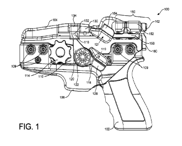
[0014] FIG. 1 illustrates a left side view of one
embodiment of a firearm holster in accordance
with the invention.
[0015] FIG. 2 illustrates a right side view of one
embodiment of a firearm holster in
accordance with the invention.
[0016] FIG. 3 illustrates a left front perspective view of
one embodiment of a firearm holster
in accordance with the invention.
[0017] FIG. 4 illustrates a left back perspective view of
one embodiment of a firearm holster
with a secondary lock in the locked position in accordance with the invention.
[0018] FIG. 5 illustrates a left back perspective view of
one embodiment of a firearm holster
with a secondary lock in the unlocked position in accordance with the
invention.
[0019] FIG. 6 illustrates a right back perspective view of
one embodiment of a firearm holster
with a secondary lock in the locked position in accordance with the invention.
[0020] FIG. 7 illustrates a right back perspective view of
one embodiment of a firearm holster
with a secondary lock in the unlocked position in accordance with the
invention.
CA 03147475 2022-2-9
WO 2021/034732 PCT/US2020/046585
8
[0021] FIG. 8 illustrates a right front perspective view of
one embodiment of a firearm holster
with a secondary lock and a drop lock in the locked position in accordance
with the invention.
[0022] FIG. 9 illustrates a back view of one embodiment of
a firearm holster with a secondary
lock in the locked position in accordance with the invention.
[0023] FIG. 10 illustrates a back view of one embodiment of
a firearm holster with a secondary
lock in the unlocked position in accordance with the invention.
[0024] FIG. 11 illustrates an exploded view of one
embodiment of a firearm holster in
accordance with the invention.
[0025] FIG. 12 illustrates an exploded view of one
embodiment of a firearm holster in
accordance with the invention.
[0026] FIG. 13 illustrates a right side view of one
embodiment of a firearm holster with a drop
lock in the locked position in accordance with the invention.
[0027] FIG. 14 illustrates a right side view of one
embodiment of a firearm holster with a top
frame removed and with a drop lock in the locked position engaging an ejection
port wall in
accordance with the invention.
[0028] FIG. 15 illustrates a tight side view of one
embodiment of a firearm holster with a drop
lock in the unlocked position in accordance with the invention.
[0029] FIG. 16 illustrates a right side view of one
embodiment of a firearm holster with a top
frame removed and with a drop lock in the unlocked position disengaged with an
ejection port wall
in accordance with the invention.
[0030] FIG. 17 illustrates a left side view of one
embodiment of a secondary lock assembly
of a firearm holster in accordance with the invention.
CA 03147475 2022-2-9
WO 2021/034732 PCT/US2020/046585
9
[0031] FIG. 18 illustrates a left back perspective side
view of one embodiment of a secondary
lock assembly of a firearm holster in accordance with the invention.
[0032] FIG. 19 illustrates a left back perspective side
view of one embodiment of a secondary
lock assembly of a firearm holster in accordance with the invention.
[0033] FIG. 20 illustrates a left back perspective side
view of one embodiment of a secondary
lock assembly of a firearm holster in accordance with the invention.
[0034] FIG. 21 illustrates a right side view of one
embodiment of a triggering lever and a
slider of a firearm holster in accordance with the invention.
[0035] FIG. 22 illustrates partial cutaway view of one
embodiment of a drive arm of a
triggering lever engaging a slider socket in accordance with the invention.
[0036] FIG. 23 illustrates an exploded view of one
embodiment of a pivotal triggering lever
assembly in accordance with the invention.
[0037] FIG. 24 illustrates a bottom front left perspective
view of one embodiment of a slider
in accordance with the invention.
[0038] FIG. 25 illustrates a partial cut away view of one
embodiment of a slider in a locked
position in accordance with the invention.
[0039] FIG. 26 illustrates a partial cut away view of one
embodiment of a slider in an unlocked
position in accordance with the invention.
[0040] FIG. 27 illustrates a left side view of one
embodiment of a firearm holster held by a
user in accordance with the invention.
[0041] FIG. 28 illustrates a left side view of one
embodiment of a firearm holster held by a
user in accordance with the invention.
CA 03147475 2022-2-9
WO 2021/034732
PCT/US2020/046585
[0042] FIG. 29 illustrates a left side view of one
embodiment of active locking mechanisms
attached to a backbone of a firearm holster in accordance with the invention.
[0043] FIG. 30 illustrates a right side view of one
embodiment of active locking mechanisms
attached to a backbone of a firearm holster in accordance with the invention.
[0044] FIG. 31 illustrates a left back perspective view of
one embodiment of active locking
mechanisms attached to a backbone of a firearm holster in accordance with the
invention.
[0045] FIG. 32 illustrates a left front perspective view of
one embodiment of active locking
mechanisms attached to a backbone of a firearm holster in accordance with the
invention.
[0046] FIG. 33 illustrates a right back perspective view of
one embodiment of a firearm having
an ejection port.
[0047] FIG. 34 illustrates a right front perspective view
of one embodiment of a top frame in
accordance with the invention.
[0048] The images in the drawings are simplified for
illustrative purposes and are not depicted
to scale. Within the descriptions of the figures, similar elements are
provided similar names and
reference numerals as those of the previous figure(s). The specific numerals
assigned to the
elements are provided solely to aid in the description and are not meant to
imply any limitations
(structural or functional) on the invention.
[0049] The appended drawings illustrate exemplary
configurations of the invention and, as
such, should not be considered as limiting the scope of the invention that may
admit to other
equally effective configurations. It is contemplated that features of one
configuration may be
beneficially incorporated in other configurations without further recitation.
CA 03147475 2022-2-9
WO 2021/034732 PCT/US2020/046585
11
DETAILED DESCRIPTION
[0050] The embodiments of the disclosure will be best
understood by reference to the
drawings, wherein like parts are designated by like numerals throughout. It
will be readily
understood that the components, as generally described and illustrated in the
Figures herein, could
be arranged and designed in a wide variety of different configurations or be
entirely separate.
Thus, the following detailed description of the embodiments of the system and
method of the
disclosure, as represented in the Figures, is not intended to limit the scope
of the disclosure, as
claimed, but is merely representative of possible embodiments of the
disclosure.
[0051] FIGS. 1-34 illustrate embodiments of a firearm
holster 100 in accordance with the
invention. FIG. 1 shows a firearm holster 100 enclosing a firearm 102. The
firearm holster 100
includes a top frame 104 and a lower body 106. The firearm holster 100 is
configured to receive
and securely engage the firearm 102. In some embodiments, the firearm holster
100 will be form
fitted to snugly secure the firearm 102, providing one level of retention. A
backbone 110 is
operable to couple the top frame 104 of the firearm holster 100 to the lower
body 106 of the firearm
holster 100. As illustrated in FIG. 11, frame couplers 111 are operable to
couple to a top frame
104 and lower body 106 of a firearm holster 100. The frame couplers 111 are
operable to align
with holes 105 in the top frame 104 and holes 107 in the lower body 106 and
receive and secure
screws 109 to assemble the firearm holster 100. Screws or other means for
fastening the lower
body 106 to the top frame 104 are rated to withstand 1,000 pounds of force.
Other means for
attaching the lower body 106 to the top frame 104 include adhesive, bolts, and
rivets, for example.
In some embodiments, a triggering lever mount 112 is defined by the backbone
110 and is operable
to receive and secure a pivotal triggering lever 116. In some embodiments, the
triggering lever
CA 03147475 2022-2-9
WO 2021/034732
PCT/US2020/046585
12
mount 112 is hexagonal, as illustrated in FIG. 11. In one embodiment, the
backbone 110 includes
mount 114 attached to the backbone body operable to secure to a belt clip or a
harness, for example.
[0052] A slider 130 is slidably attached to and operable to
slide along a slider base 138 atop
the frame 104. As illustrated in FIGS. 13-16, the slider 130 is operable to
slide between the locked
position A to the unlocked position B in the direction of arrow 113. A
resettable drop lock 146 is
pivotably attached to the slider base 138 via a resettable drop lock mount 144
defined by the slider
base 138. The resettable drop lock 146 is configured to pivot on resettable
drop lock screw 149
between a locked position and an unlocked position, as illustrated in FIGS. 13-
16. A drop lock
spring 148 is disposed between the resettable drop lock 146 and the slider
base 138 and operable
to bias the resettable drop 146 into the locked position A. In the locked
position, the resettable
drop lock 146 extends through a resettable drop lock passage 172 (shown in
FIGS. 13 and 14) and
sits within the ejection port 174 of the firearm 102. (The ejection port 174
of the firearm 102 is
illustrated in FIGS. 14 and 16. The resettable drop lock 146 is spring biased
by drop lock spring
148 and, when in the down and locked position, the firearm 102 cannot be
removed from the
holster 100, as the spring bias forces the resettable drop lock 146 into the
ejection port 174,
providing a second level of retention. In operation, when the resettable drop
lock 146 is in the
locked position A, the end of the resettable drop lock 146 will protrude into
the ejection port 174.
Should a user attempt to remove the firearm 102 from the holster 100 while the
resettable drop
lock 146 is in the locked position, the end of the resettable drop lock 146
will make contact with
an ejection port wall 176, preventing the firearm 102 from moving towards the
back of the holster
100. When in the unlocked position, slider 130 will be slid towards the back
of the holster 100
and the resettable drop lock 146 will pivot out of the ejection port 174. The
drop lock spring 148
is operable to automatically bias the resettable drop lock 146 into the locked
position, eliminating
CA 03147475 2022-2-9
WO 2021/034732
PCT/US2020/046585
13
the need for the user to lock the secondary level of retention. Once a user
inserts the firearm 102
into the holster 100, the resettable drop lock 146 will automatically pivot
into and lock within the
ejection port 174.
[00531 As illustrated in FIGS. 25-26, the slider 130
defines a slider spring cavity 136 operable
to receive and secure a slider spring 165. The slider base 138 defines a
slider base spring cavity
140 operable to receive and enclose the slider spring 165. As illustrated in
FIG. 25, the spring
165 biases the slider 130 towards the front of the holster 100 into a locked
position. Upon receipt
of a force by a user to move the slider 130 from the locked position into an
open position, as
illustrated in FIG. 26, the spring 165 will compress and thereby bias the
slider 130 into the locked
position.
[00541 In one embodiment, to provide a second level of
retention, a pivotal triggering lever
115 is attached to the firearm holster 100 via a triggering lever mount 112,
as illustrated in FIG.
11. In the embodiment illustrated in the Figures, the triggering lever mount
112 is a male
hexagonal mount. The pivotal triggering lever 115 has a triggering arm 116
opposite a drive arm
120. As illustrated in FIG. 22, a drive head 118 of the drive arm 120 engages
an extension arm
134 of the slider 130 via socket 132. A thumb pad 128 is attached to the
triggering arm 116. In
one embodiment, triggering lever mount 112 is integrated directly or
overmolded into the top
frame 104. For example, the triggering lever mount 112 may be manufactured
from a metal such
as aluminum and the top frame 104 may be manufactured from plastic by
injection mold. The
triggering lever mount 112 may be placed in the mold for the frame 104 and
overmolded into the
top frame 104. In some embodiments, the triggering lever mount 112 and the top
frame 104 may
be manufactured together and from the same materials, such as plastic or
metal.
CA 03147475 2022-2-9
WO 2021/034732
PCT/US2020/046585
14
100551 FIG. 11 illustrates an exploded view of the holster
100 in accordance with
embodiments of the present invention. A triggering lever spring tension device
124 is configured
to engage with and couple to the triggering lever mount 112. A triggering
lever spring 126 is
configured to sit within a spring channel 127 of the triggering lever 115.
FIG. 21 illustrates the
triggering lever spring tension device 124 having a cylindrical shaft portion
129 defining an
internal female hexagonal connector 131 operable to couple to the triggering
lever mount 112.
The triggering lever spring tension device 124 further defines a spring end
opening 137. A
triggering lever assembly screw 122 secures the triggering lever to the
triggering lever mount 112.
100561 As illustrated in the Figures, one embodiment of the
triggering assembly screw 122
defines a plurality of holes 125 for use with a spanner wrench to tighten or
loosen triggering
assembly screw 122.
[0057] A novel aspect of the invention enables the user to
adjust the force required to rotate
the triggering lever 115 to remove the firearm 102 from the holster 100. This
is advantageous for
applications that may require stronger levels of retention by the holster 100,
such as crowd control
or riots. Using the spring tension of the triggering lever spring 126, the
user may selectively attach
the triggering lever spring tension device 124 to the triggering lever mount
112 along the
hexagonal coupler to increase or decrease the tension in the triggering lever
spring 126. Referring
to FIG. 11, triggering lever spring tension device 124 has a central axis 161.
When uncoupled
from the triggering lever mount 112, the user can rotate the triggering lever
spring tension device
124 on the axis 161 in either direction as indicated by arrow 163. By rotating
the triggering lever
spring tension device 124 by 60 degrees in one direction, tension in the
triggering lever spring 126
will increase, and by rotating the triggering lever spring tension device 124
by 60 degrees in the
opposite direction, tension in the triggering lever spring 126 will decrease.
By using increments
CA 03147475 2022-2-9
WO 2021/034732
PCT/US2020/046585
of 60 degrees, the hexagonal coupler 112 and the female hexagonal connector
131 will align to
mate and can be fastened together. A user may choose to rotate the triggering
lever spring tension
device 124 by multiple increments of 60 degrees to increase or decrease the
tension in the
triggering lever spring 126 for as far as the spring will coil or uncoil. As
illustrated in the Figures,
the trigger lever mount 112 and the female hexagonal connector 131 are male
and female and
hexagonal in shape. However, in other embodiments, the trigger lever mount 112
and the female
hexagonal connector 131 may be other geometric shapes, such as a square or
octagon, for example.
In embodiments utilizing other shaped connectors, the increments to rotate the
triggering lever
spring tension device 124 will vary.
100581 In one embodiment, when the holster 100 is assembled
(as illustrated in FIG. 1), the
triggering lever spring 126 is inserted into the spring channel 127. A first
end of the triggering
lever spring 126 protrudes through a triggering lever spring end opening 135
in the triggering lever
115. (Triggering lever spring end opening 135 is illustrated in FIG. 23). A
second end of the
triggering lever spring 126 protrudes through a triggering lever spring end
opening 137 in the
triggering lever spring tension device 124. Triggering lever 115 is slid over
the cylindrical portion
139 of the triggering lever spring tension device 124 such that the triggering
lever 115 is free to
rotate around the cylindrical portion 139. However, this rotation is countered
by the spring force
from the triggering lever spring 126 as each end of the triggering lever
spring 126 engages with
the spring end openings 135 and 137.
[0059] As illustrated in FIG. 11, the triggering lever
spring tension device 124 rigidly connects
to the triggering lever mount 112 by pressing the female hexagonal connector
131 of the triggering
lever spring tension device 124 over the hexagonal triggering lever mount 112.
Once the triggering
lever spring tension device 124 is pressed onto the hexagonal triggering lever
mount 112, the
CA 03147475 2022-2-9
WO 2021/034732
PCT/US2020/046585
16
triggering lever 118 is secured between the triggering lever spring tension
device 124 and the
backbone 110. The triggering lever 115 can rotate around the cylindrical shaft
portion 138. The
rotation of the triggering lever 115 around the cylindrical shaft portion 138
is limited by the
triggering lever spring 134. Triggering lever assembly screw 122 is operable
to screw the assembly
into the triggering lever mount 112.
[0060] In one embodiment, as illustrated in FIGS. 18-20, to
provide a third level of retention,
a secondary lock assembly 150 is operable to retain a firearm 102 in a holster
100. The secondary
lock assembly 150 includes a secondary lock body 152 defining a helical lock
shaft passage 153.
The secondary lock body 152 defines a sear lever channel 155. The secondary
lock body 152
defines a helical lock guide pin aperture 157. The secondary lock body 152 is
operable for
attachment to a firearm holster via coupler 159. A sear lever 156 is pivotally
attached to the
secondary lock body 152. The sear lever 156 is operable to pivot from a locked
position to an
unlocked position in the direction of arrow 121. In the locked position (the
locked position is show
in FIG. 9), the helical lock spring is compressed between the secondary lock
body 152 and the
helical lock shaft 158. The sear lever 156 is operable to engage and retain
the helical lock shaft
158 to prevent it from extending from the secondary lock body 152.
[0061] A secondary thumb pad 154 is attached to the sear
lever 156 and is operable to receive
a force from a user to pivot the sear lever 156. A helical lock shaft 158 is
disposed within the
helical lock shaft passage 153 and is operable to rotate and extend from the
helical lock shaft
passage 153 upon receipt of a force from a user applied to the secondary thumb
pad 154. The
helical lock shaft 158 defines a helical guide slot 166. The helical guide
slot 166 is operable to
enable a rotation of the helical lock shaft 158 by engaging a helical guide
pin 164 as it extends
from the secondary lock body 152. A helical lock bar 160 is secured to the
helical lock shaft 158
CA 03147475 2022-2-9
WO 2021/034732
PCT/US2020/046585
17
by a helical lock fastener 162 and is operable to rotate from the locked
position C to an unlocked
position D in the direction of row 117, as illustrated in FIGS. 9-10. A
helical guide pin 164 is
disposed within the helical guide pin aperture 157 of the secondary lock body
152. The helical
guide pin 164 protrudes into the helical guide slot 166 and is operable to
retain the helical lock bar
160 in the helical lock shaft passage 153. A helical lock spring 168 is
disposed between the
secondary lock body 152 and the helical lock shaft 158. The helical lock
spring 168 is operable to
apply a force to the helical lock shaft 158 to bias the helical lock shaft 158
into the unlocked
position C. A helical sear lever spring 170 is disposed between the secondary
lock body 152 and
the sear lever and is operable to apply a force to the sear lever 156 to bias
the sear lever into the
locked position C. Upon receipt of an upward force of by a user on the
secondary thumb pad 154
in the direction of arrow 121, the sear lever 156 will disengage the helical
lock shaft 158. Once
the sear lever 156 is disengaged from the helical lock shaft 158, the helical
lock shaft 158 will
extend outward from the secondary lock body 152 and rotate the helical lock
bar 160.
[0062] This invention provides several unique advantages
over the prior art. First, the
configuration allows for a comfortable and quick removal of the firearm 102
from the holster 100
using natural, ergonomic thumb motions. This configuration reduces the amount
of training
required to train a user to quickly remove the firearm 102 from the holster
100. To remove the
firearm 102 from the holster 100, a user will first grip the firearm 102 in a
typical shooting grip.
The user will then use their thumb to press thumb pad 154 towards the top of
the holster 100,
thereby rotating the helical lock bar 160 from the locked position C to the
unlocked position D.
Next, still holding the firearm 102 in the shooting grip, the user will press
down on the thumb pad
128 of the triggering arm 116. Pressing the triggering arm 116 down will cause
the triggering
lever 115 to rotate around the cylindrical shaft portion 129 and drive arm 120
will rotate towards
CA 03147475 2022-2-9
WO 2021/034732
PCT/US2020/046585
18
the back of the firearm holster 100. As the drive arm 120 rotates toward the
back of the firearm
holster 100, it will pull the slider 130 toward the back of the firearm
holster 100 from the locked
position A to the unlocked position B via the extension arm 134. When the
slider 130 is pulled
towards the back of the firearm holster 100, the resettable drop lock 146 will
pivot up and out of
the ejection port 174 of the firearm 102. Once the resettable drop lock 146 is
out of the injection
port 174, the firearm 102 can be removed from the holster 100 by using enough
force required to
pull the firearm 102 from the holster 100.
100631 Another novel feature of the invention is that the
user is able to maintain a perfect firing
grip on the firearm 102 during removal from the holster 100, as illustrated in
FIGS. 27 and 28.
The user will engage the active locking mechanisms 108 to remove the firearm
102 from the holster
100. The active locking mechanisms 108 are illustrated in FIGS. 29-32. In FIG.
27, the hand 101
of a user grips the firearm 102 in the holster 100. The user will first use
their thumb to move
secondary thumb pad 154 up in the direction of arrow 121 to unlock the
secondary lock assembly
150. The user will then and then press down on the primary thumb pad 128 to
release engage the
pivotal triggering lever 115, thereby sliding the slider 130 and rotating the
resettable drop lock 146
from the ejection port 174. This orientation of the thumb pads 128 and 154
follows the
biomechanics of a person's thumb to enable an ergonomic pair of motions to
release the firearm
102 from the holster 100. As illustrated in FIG. 28, the same grip of the
user's hand 101 is used
to hold the gun in the firing position. This shortens the time to adjust the
grip of on the firearm
102 after the removal from the holster 100 and requires minimal training to
become familiar with
unlocking and locking the firearm 102 in the holster 100.
[0064] For the purposes of promoting an understanding of
the principles of the invention,
reference has been made to the preferred embodiments illustrated in the
drawings, and specific
CA 03147475 2022-2-9
WO 2021/034732
PCT/US2020/046585
19
language has been used to describe these embodiments. However, this specific
language intends
no limitation of the scope of the invention, and the invention should be
construed to encompass all
embodiments that would normally occur to one of ordinary skill in the art. The
particular
implementations shown and described herein are illustrative examples of the
invention and are not
intended to otherwise limit the scope of the invention in any way. For the
sake of brevity,
conventional aspects of the system (and components of the individual operating
components of
the system) may not be described in detail. Furthermore, the connecting lines,
or connectors shown
in the various figures presented are intended to represent exemplary
functional relationships and/or
physical or logical couplings between the various elements. It should be noted
that many
alternative or additional functional relationships, physical connections or
logical connections may
be present in a practical device. Moreover, no item or component is essential
to the practice of the
invention unless the element is specifically described as "essential" or
"critical". Numerous
modifications and adaptations will be readily apparent to those skilled in
this art without departing
from the spirit and scope of the present invention.
CA 03147475 2022-2-9