Note: Descriptions are shown in the official language in which they were submitted.
METHODS AND SYSTEMS FOR IDENTIFYING A LIQUID LEVEL WITHIN A
RESERVOIR BEING PRODUCED VIA A THERMALLY-STIMULATED GRAVITY
DRAINAGE PROCESS
TECHNICAL FIELD
[0001] The present disclosure relates to identifying a liquid level within
a
reservoir whose hydrocarbon material is being produced via a thermally-
stimulated
gravity drainage process.
BACKGROUND
[0002] Steam assisted gravity drainage (SAGD) is an in-situ process for
recovering heavy oil and bitumen from subsurface reservoirs. During SAGD, high
pressure steam is injected via an injection well to heat the hydrocarbon
material,
thus reducing its viscosity. This causes the heated hydrocarbon material to
drain
into a production well where it can then be pumped to the surface. In order to
pump the fluids to the surface, a pumping system, installed within the
production
well, is generally submersed within fluid received by the production well.
[0003] Many systems which effectuate the SAGD process include a fiber
optic
cable that extends from the surface of the well, through the vertical section
and
into the horizontal section. This fiber optic cable is capable of sensing
various
parameters in the well, such as temperature. By extending through the vertical
and
horizontal sections of the well, the fiber optic cable can provides
distributed
temperature sensing (DTS) such that the local temperature at various pints in
the
production wellbore can be detected. The fiber optic cable is typically
permanently
installed to allow continuous monitoring of the well throughout its
operational
lifetime, without the need to deploy additional instruments or stop well
production.
[0004] During SAGD, the fiber optic cable is conventionally used to
monitor
the temperatures within the horizontal section of the well, for the purpose
of, for
example, to detect casing leaks or optimize operation. Despite the fact that
the
1
Date Recue/Date Received 2022-02-03
fiber optic cable extends from the surface through the vertical section and
into the
horizontal section, it is typically not used to monitor any parameters in the
vertical
section of the wellbore.
[0005] In SAGD processes, it is useful to know the location of the liquid
level
in the vertical section of the production well. Knowing the liquid level can
help
determine bottom hole pressure (BHP) and can be used to monitor the
productivity
and/or deliverability of the well. Accordingly, there is a need to
conveniently
identify the location of the liquid level in the vertical section of a SAGD
production
well.
SUMMARY
[0006] In one aspect there is provided a method for identifying a liquid
level
within a reservoir from which hydrocarbon material is being produced by a
thermally-stimulated gravity drainage-based hy-drocarbon production process.
The
method comprising: obtaining subsurface temperature data representative of
subsurface temperatures within the reservoir, and identifying a liquid level
within
the reservoir based on the obtained subsurface temperature data.
[0007] In some examples, the obtained temperature data comprises, for
each
one of a plurality of vertical depths from the surface, vertical depth-based
subsurface temperature information.
[0008] In some examples, the vertical depth-based subsurface temperature
information is vertical depth-based subsurface temperature information within
a
production well through which the hydrocarbon material is being produced.
[0009] In some examples, successive depths, of the plurality of depths,
are
spaced apart from each other by at least five (5) metres.
[0010] In some examples, the vertical depth-based subsurface temperature
information includes: (i) temperature that is representative of the
temperature of
the reservoir at the vertical depth, and (ii) a temperature variability factor
that is
2
Date Recue/Date Received 2022-02-03
representative of the variability of the temperature of the reservoir at the
vertical
depth.
[0011] In some examples, the temperature variability factor is a standard
deviation of a set of values defined by: (i) the temperature information that
is
representative of a temperature of the reservoir at the vertical depth and
(ii) for
each one of at least two shallower vertical depths, of the plurality of
vertical depths,
disposed immediately above the vertical depth, independently, the temperature
information that is representative of the temperature of the reservoir at the
shallower vertical depth.
[0012] In some examples, each one of (i) the temperature information,
that is
representative of the temperature of the reservoir at the vertical depth, and
(ii) the
temperature information for each one of the at least two shallower vertical
depths,
is defined relative to a standard, and the standard is a known temperature
within
the liquid.
[0013] In some examples, the temperature information, that is
representative
of the temperature of the reservoir at the vertical depth, is based on a
relative
difference between temperature that is sensed at the vertical depth and the
standard, and, for each one of at least two shallower vertical depths, of the
plurality
of vertical depths, disposed immediately above the vertical depth,
independently,
the temperature information, that is representative of the temperature of the
reservoir at the shallower vertical depth, is based on a relative difference
between
temperature that is sensed at the shallower vertical depth and the standard.
[0014] In some examples, the method further comprises, for each one of:
(i)
the temperature that is sensed at the vertical depth, sensing the temperature
with
a respective temperature sensor, and (ii) for the temperature that is sensed
at each
one of the at least two shallower vertical depths, sensing the temperature
with a
respective temperature sensor.
3
Date Recue/Date Received 2022-02-03
[0015] In some examples, the respective temperature sensor is a fiber
optic
cable configured to sense temperatures along a length of the fiber optic
cable.
[0016] In some examples, the known temperature within the liquid is a
temperature representative of the temperature of the liquid within a pump
disposed
within the production well for effectuating production of the hydrocarbon
material.
[0017] In some examples, the identifying a liquid level includes
determining a
vertical depth, from the surface, of the liquid level, wherein the determined
vertical
depth is the vertical depth at which: (i) the temperature information is
representative of a temperature of the reservoir which exceeds a predetermined
value and (ii) the variability factor exceeds a predetermined value.
[0018] In some examples, the identifying a liquid level includes
determining a
vertical depth, from the surface, of the liquid level, wherein the determined
vertical
depth is the vertical depth at which: (i) the temperature information is
representative of a temperature of the reservoir which exceeds 10 /0 and (ii)
the
variability factor exceeds 60%.
[0019] In some examples, identifying a liquid level includes determining
a
vertical depth, from the surface, of the liquid level, wherein the determined
vertical
depth is the vertical depth at which: (i) the temperature information is
representative of a temperature of the reservoir which exceeds 2.5% and (ii)
the
variability factor exceeds 300%.
[0020] In some examples, identifying a liquid level includes determining
a
vertical depth, from the surface, of the liquid level, wherein the determined
vertical
depth is the vertical depth at which: (i) the temperature information is
representative of a temperature of the reservoir which exceeds 7% and (ii) the
variability factor exceeds 100%.
[0021] In some examples, the method further comprises: in response to the
determination that the vertical depth, from the surface, of the liquid level,
is below
4
Date Recue/Date Received 2022-02-03
a flow discharging communicator, through which a production-stimulating fluid
is
being discharged into the production well from the reservoir, by less a
predetermined value, increasing the rate at which the hydrocarbon material is
being
produced from the reservoir via the production well.
[0022] In some examples, the method further comprises: in response to the
determination that the vertical depth, from the surface, of the liquid level,
is below
a flow discharging, through which a production-stimulating fluid is being
discharged
into the production well from the reservoir, by less a predetermined value,
presenting an indication of a potential injector flooding condition via an
output
device.
[0023] In some examples, the method further comprises: in response to the
determination that the vertical depth, from the surface, of the liquid level,
is above
a flow receiving communicator, through which the hydrocarbon material is being
conducted into the production well from the reservoir, by less than a
predetermined
value, decreasing the rate at which the hydrocarbon material is being produced
from the reservoir via the production well.
[0024] In some examples, the method further comprises: in response to the
determination that the vertical depth, from the surface, of the liquid level,
is above
a flow receiving, through which the hydrocarbon material is being conducted
into
the production well from the reservoir, by less than a predetermined value,
presenting an indication of a potential steam coning condition via an output
device.
[0025] In some examples, the plurality of vertical depths from the
surface are
depths from the surface relative to a well geometry and do not correspond to
true
vertical depths. The method further comprising: determining a true vertical
depth
(TVD) at the vertical depth of the liquid level based on the well geometry.
[0026] In some examples, the well geometry is obtained from a well
directional survey.
Date Recue/Date Received 2022-02-03
[0027] In some examples, the method further comprises: determining a
bottom hole pressure, wherein the bottom hole pressure is calculated by adding
a
surface casing pressure to the product of the true vertical depth, a
gravitational
constant and a fluid emulsion density, wherein the surface casing pressure is
measured at the surface of the wellbore and the fluid emulsion density is a
property
of the fluid in the wellbore.
[0028] In some examples, the method further comprises: comparing the
determined bottom hole pressure to a measured bottom hole pressure.
[0029] In some examples, the method further comprises: determining a
volume of wellbore fluid in a vertical section of the production well based on
the
true vertical depth at the vertical depth of the liquid level, the geometry of
the well,
and a fluid emulsion density.
[0030] In some examples, the method further comprises: obtaining a total
well production volume from a well test of the production well, and
determining a
reservoir capacity by subtracting the volume of wellbore fluid in the vertical
section
of the production well from the total well production volume.
[0031] In some examples, the method further comprises: injecting a
chemical
agent for stimulating production in response to determining that the reservoir
capacity is below a low production threshold.
[0032] In some aspects, the present disclosure describes a system for
identifying a liquid level within a reservoir from which hydrocarbon material
is being
produced by a thermally-stimulated gravity drainage-based hydrocarbon
production
process. The system comprises one or more processor devices and one or more
memories storing machine-executable instructions which, when executed by the
one or more processor devices, cause the system to perform any of the
preceding
example aspects of the method.
6
Date Recue/Date Received 2022-02-03
[0033] In some aspects, the present disclosure describes a system for
identifying a liquid level within a reservoir from which hydrocarbon material
is being
produced by a thermally-stimulated gravity drainage-based hydrocarbon
production
process. The system comprises a temperature sensor, one or more processor
devices, and one or more memories storing machine-executable instructions,
which, when executed by the one or more processor devices, cause the system to
obtain subsurface temperature data representative of subsurface temperatures
within the reservoir, using the temperature sensor, and identify a liquid
level within
the reservoir based on the obtained subsurface temperature data.
[0034] In some examples, the temperature sensor is a distributed
temperature sensing (DTS) device, configured to sense temperatures along a
length
of the DTS device.
[0035] In some examples, the distributed temperature sensing (DTS) device
is a fiber optic cable.
[0036] In some example aspects, the present disclosure described a non-
transitory computer-readable medium storing machine-executable instructions
thereon. The instructions, when executed by one or more processors, cause the
processor to perform any of the preceding example aspects of the method.
[0037] In some embodiments, the techniques described herein can be used
to
identify the liquid level in the vertical section of the production well. In
this respect,
the techniques use presently underutilized data obtained from existing fiber
optic
cables deployed in the vertical section of the production well. The techniques
allow
operators to monitor liquid level, bottom hole pressure, and well
productivity/deliverability and identify possible issues within the injection
and
production wells based on the liquid level.
BRIEF DESCRIPTION OF THE DRAWINGS
7
Date Recue/Date Received 2022-02-03
[0038] Reference will now be made, by way of example, to the accompanying
drawings which show example embodiments, and in which:
[0039] Figure 1 illustrates a schematic diagram of a well pair of a
thermally-
stimulated gravity drainage process for producing hydrocarbon material from a
reservoir;
[0040] Figure 2 is a schematic illustration of a thermally-stimulated
gravity
drainage process implemented via a well pair; and
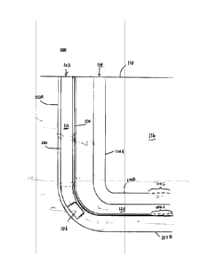
[0041] Figure 3 depicts a close-up of a portion of the vertical section
of a
production well within which a fiber optic cable is being used for enabling
detection
of the liquid level.
[0042] Similar reference numerals are used in different figures to denote
similar components.
DETAILED DESCRIPTION
[0043] The present disclosure describes methods for identifying the
liquid
level within a reservoir from which hydrocarbon material is being produced by
a
thermally-stimulated gravity drainage-based hydrocarbon production process,
and
systems for implementing such methods. The liquid level is identified based on
obtained subsurface temperature data that is representative of subsurface
temperatures of the reservoir.
[0044] Figure 1 illustrates a schematic layout of a system 100 for
carrying out
a process for producing hydrocarbon material from a hydrocarbon-containing
reservoir 116. In some embodiments, for example, the hydrocarbon-containing
reservoir includes an oil sands reservoir, and the hydrocarbon material
includes
heavy hydrocarbon material, such as bitumen. In this respect, in some
embodiments, for example, the reservoir is an oil sands reservoir.
[0045] The system 100 includes a pair of wells, 102, 114. Each of the
wells
102, 114, independently, extends into the reservoir 116 from the surface 110.
The
8
Date Recue/Date Received 2022-02-03
well 102 includes a respective vertical section 102A and a respective
horizontal
section 102B. The well 114 includes a respective vertical section 114A and a
respective horizontal section 114B. The well 114 functions as an injection
well and
the well 102 functions as a production well. Production-stimulating fluid is
injected
via the injection well 114 to stimulate production of the hydrocarbon material
via
the production well 102. In some embodiments, for example, the producing of
the
hydrocarbon material via the production well 102 is effected while the
production-
stimulating fluid is being injected by the injection well 114. In this
respect, in some
embodiments, for example, the hydrocarbon production process is a continuous
process.
[0046] In some embodiments, for example, a production-stimulating fluid
is
conducted via an injection string, disposed within the injection well 114, and
injected into the reservoir via a flow discharging communicator 114C. In some
embodiments, for example, the flow discharging communicator 114C is defined by
a plurality of injection ports defined within a slotted liner that is hung
from a casing
string that is disposed within the injection well 114. In some embodiments,
for
example, the plurality of injection ports are disposed along a reservoir
interface
that defines the interface between the injection well 114 and the reservoir
116. In
some embodiments, for example, the ports are disposed within a horizontal
section
114B of the injection well 114.
[0047] In some embodiments, for example, the production well 102 includes
a
flow communicating receiver 102C for receiving fluid that is being conducted
within
the reservoir 116 in response to the injection of the production-stimulating
fluid. In
some embodiments, for example, the flow receiving communicator 102C is defined
by a plurality of ports. In some embodiments, for example, the ports are
defined
within a slotted liner hung from a casing string that is disposed within the
production well 104. In some embodiments, for example, the ports are disposed
within a horizontal section 102B of the production well 102.
[0048] The hydrocarbon material is produced via the production well 102
by
artificial lift, such as, for example, by a pumping system 106. In some
9
Date Recue/Date Received 2022-02-03
embodiments, for example, the pumping system 106 is an electrical submersible
pump (ESP). The ESP includes a motor that is located below the pump, such that
the fluid being pumped can act as a coolant for the motor. The motor converts
electrical energy into rotational energy which in turn causes the pump to
rotate.
The pump converts the rotational energy into kinetic energy and causes the
fluid to
flow up and out of the well 102. In some embodiments, for example, the pump
has
an intake that is submersed within the fluid that is received by the
production well.
If the intake is not submersed, the pump will not be able to draw in fluid to
pump
to the surface. A production string 112 (e.g. tubing) extends uphole from the
pumping system 106 to the surface 110, for conducting fluid, discharged from
the
pumping system 106, to the surface 110.
[0049] Referring to Figure 2, a hydrocarbon production process can be
implemented via the well pair, so long as fluid communication is effected
between
the wells 102, 114 via a communication zone 118 (i.e. fluid is conductible
(for
example, by flowing)) such that the injected production-stimulating fluid
effects
mobilization of the hydrocarbon material within the reservoir, and the
mobilized
hydrocarbon material is conducted to the production well 102 via the
communication zone 118 for production via the production well 102. The
conduction
of the hydrocarbon material to the production well 102 is effected in response
to an
applied driving force (for example, application of a fluid pressure
differential, or
gravity, or both). In some embodiments, for example, the production-
stimulating
fluid functions as a drive fluid effecting conduction (or transport) of
hydrocarbon
material to the production well 102. In some embodiments, for example, the
production-stimulating fluid functions as a heat transfer fluid, supplying
heat to the
hydrocarbon material, such that viscosity of the hydrocarbon material is
sufficiently
reduced (in such state, the hydrocarbon material is said to be mobilized),
such that
the hydrocarbon material can be conducted to the production well 102 by a
driving
force, such as, for example, a pressure differential or gravity. In some
embodiments, for example, the production-stimulating fluid functions as both a
drive fluid and a heating fluid. In some embodiments, for example, the
hydrocarbon
material is produced along with some of the injected production-stimulating
fluid.
While the wells 102, 114 are disposed in fluid communication through the
Date Recue/Date Received 2022-02-03
communication zone 118, production-stimulating fluid is injected into the
reservoir
116 such that the hydrocarbon material is conducted to the well 102, via the
communication zone 118, and produced through the well 102.
[0050] In some embodiments, for example, the production-stimulating fluid
includes gaseous material, such as, for example, steam. In this respect, in
those
embodiments where the production-stimulating fluid functions as a heating
fluid, in
some of these embodiments, for example, at least a portion of the production-
stimulating fluid that has heated the hydrocarbon material (as described
above)
become condensed, such that fluid that is being produced via the production
well
102 includes hydrocarbon material and condensed production-stimulating fluid.
In
those embodiments where the gaseous material includes steam, in some of these
embodiments, for example, the condensed production-stimulating fluid includes
water. In those embodiments where the condensed production-stimulating fluid
includes water, the fluid being produced via the production well 102 is an
emulsion.
[0051] In some embodiments, for example, the hydrocarbon production
process includes a thermally-stimulated gravity drainage-based hydrocarbon
production process that is implemented via the well pair. In such processes,
the
production-stimulating fluid is gaseous and effectuates mobilization of the
hydrocarbon material by at least heating the hydrocarbon material. The
mobilized
hydrocarbon material displaces the production-stimulating fluid in response to
density differences, with effect that the mobilized hydrocarbon material is
conducted to the production well 102 for production via the production well
102.
This process, of conduction of the mobilized hydrocarbon material to the
production
well, is commonly referred to as "gravity drainage".
[0052] In systems which implement thermally-stimulated gravity drainage-
based hydrocarbon production processes, the horizontal section 11413 of the
injection well 114 is vertically spaced from the horizontal section 10213 of
the
production well 102, such that the horizontal section 11413 of the injection
well 114
is disposed above the horizontal section 10213 of the production well 102,
such as,
for example, by at least three (3) metres, such as, for example, by at least
five (5)
11
Date Recue/Date Received 2022-02-03
metres. A production phase (i.e. when hydrocarbon material is being produced
via
the production well 102) of the thermally-stimulated gravity drainage-based
hydrocarbon production process occurs after the communication zone 118 has
been
established for effectuating flow communication between the mobilized
hydrocarbon
material and the production well 102.
[0053] With respect to thermally-stimulated gravity drainage-based
hydrocarbon production processes being implemented via the well pair,
initially, the
reservoir 116 has relatively low fluid mobility (such as, for example, due to
the fact
that the hydrocarbon material within the reservoir 116 is highly viscous) such
that
the communication zone 118 is not present. In order to enable the injected
production-stimulating fluid (being injected through the injection well 114)
to
promote the conduction of the reservoir hydrocarbons, within the reservoir
102, to
the production well 102, the communication zone 118 must be established. This
establishing of the communication zone 118 includes establishing interwell
communication between the wells 102, 114 through the interwell region 120. By
establishing the interwell communication, the conduction of the mobilized
hydrocarbon material, through the interwell region 120, is enabled such that
the
mobilized hydrocarbon material is received and produced by the production well
102. The interwell communication can be established during a "start-up" phase
of
the thermally-stimulated gravity drainage-based hydrocarbon production
process.
In some embodiments, for example, during the start-up phase, the interwell
region
120 is heated. In some embodiments, for example, the heat is supplied to the
interwell region 120 by effecting circulation of a start-up phase fluid (such
as
steam, or a fluid including steam) in one or both of the wells 102, 114. The
heat
that is supplied to the interwell region 120 heats the reservoir hydrocarbons
within
the interwell region 120, thereby reducing the viscosity of the reservoir
hydrocarbons. Eventually, the interwell region 120 becomes heated to a
temperature such that the hydrocarbon material is sufficiently mobile (i.e.
the
hydrocarbon material has been "mobilized") for displacement to the production
well
102 by at least gravity drainage. In this respect, eventually, sufficient
hydrocarbon
material becomes mobilized, such that this space (the interwell region 120),
previously occupied by immobile, or substantially immobile, hydrocarbon
material,
12
Date Recue/Date Received 2022-02-03
is disposed to communicate fluid between the injection well 114 and the
production
well 102 in response to a driving force, such that at least hydrocarbon
material is
conductible through this space in response to the driving force. Upon the
interwell
region 120 becoming disposed to communicate fluid between the injection well
114
and the production well 102 in response to a driving force, such that at least
hydrocarbon material is conductible through this space in response to the
driving
force, the interwell communication, between the wells 102, 114, is said to
have
become established. The development of this interwell communication signals
completion of the start-up phase and conversion to a production phase.
[0054] Referring again to Figure 2, during the production phase of a
thermally-stimulated gravity drainage-based hydrocarbon production process,
the
communication zone 118 effects flow communication between hydrocarbon
material, mobilized in response to heating by the production-stimulating fluid
injected from the injection well 114 (for example, by reduction in viscosity
caused
by the heating), and the production well 102, such that the mobilized
hydrocarbon
material is conductible to a bottom portion 118B of the communication zone
118,
by at least gravity drainage (the conduction can also, for example, be
promoted by
a pressure differential that is established between the injected production-
stimulating fluid and the production well 102, which can also, in some
embodiments, be characterized as a "drive process" mechanism), as described
above, such that liquid material 122, including the hydrocarbon material,
accumulates within the bottom portion 118B of the communication zone 118, for
subsequent production via the production well 102. In some embodiments, for
example, and as described above, at least a portion of the production-
stimulating
fluid that has heated the hydrocarbon material (as described above) become
condensed, such that, along with the mobilized hydrocarbon material, the
condensed production-stimulating fluid gravity drains to the bottom portion
118B of
the communication zone 118, with effect that the liquid material 122 also
includes
condensed production-stimulating fluid. In those embodiments where the
production-stimulating fluid includes steam, the condensed production-
stimulating
fluid includes water, such that the liquid material 122, which accumulates
within the
bottom portion of the communication zone 118, includes an emulsion.
13
Date Recue/Date Received 2022-02-03
[0055] As described above, the conduction of the mobilized hydrocarbon
material is effectuated by displacement of the injected production-stimulating
fluid,
by the mobilized hydrocarbon material, in response to density differences.
That
portion of the communication zone 118, through which the mobilized hydrocarbon
material is conducted via such displacement process (i.e. gravity drainage),
can be
referred to as a vapour chamber 118A. In those embodiments where the
production-stimulating fluid includes steam, such vapour chamber 118A is
commonly referred to as a "steam chamber". Relatedly, a liquid level 108 is
defined
between the accumulated liquid material 122 and the vapour chamber and
characterized by a vertical depth "VDo" below the surface 110. Where the
interface
is defined at a vertical depth which intersects the production well 102,
correspondingly, there is defined a liquid level 108 within the production
well 102,
defining the liquid level within the production well 102, and is also
characterized by
a vertical depth "VD1" below the surface 110, equal to that of vertical depth
VD of
the interface 108.
[0056] In some operational implementations, for example, the gas/liquid
interface defined by the liquid level 108 corresponds to an interface defined
within
the interwell region 120, between the horizontal section 114B of the injection
well
114 and the horizontal section 102B of the production well 102. In such
operational
implementations, the liquid material 122 is co-operatively emplaced relative
to the
injection well 114 such that there is an absence of interference, by the
liquid
material 122, to injection of the production-stimulating fluid into the
reservoir via
the injection well 114, while interference, by the liquid material 122, to
short-
circuiting by the production-stimulating fluid 102, is established. When the
interface
108 is disposed above the injection well 114, the liquid material 122
interferes with
injection of the production-stimulating fluid via the injection well 114,
thereby
interfering with production of the hydrocarbon material from the reservoir
116.
Under these conditions, the injection well 114 is referred to as being
flooded. When
the interface 108 is disposed below the production well, flow communication is
established between the injector well 114 and the production well 102 such
that the
production-stimulating fluid, injected from the injector well 114, is
conductible
directly to the production well 102 without having transferred some of its
heat to
14
Date Recue/Date Received 2022-02-03
hydrocarbon material within the reservoir 116, thereby contributing to process
inefficiencies.
[0057] In parallel, as the mobilized hydrocarbon material drains to the
bottom
portion 118B of the communication zone 118, space previously occupied by the
hydrocarbon material within the reservoir 116 becomes occupied by the injected
production-stimulating fluid, thereby exposing a fresh hydrocarbon material
surface
for receiving heat from the production-stimulating fluid (typically, by
conduction).
This repeated cycle of heating, mobilization, drainage, and establishment of
heat
transfer communication between the production-stimulating fluid and a freshly
exposed hydrocarbon material source results in the growth of the vapour
chamber
118A (e.g. steam chamber) of the communication zone 118, with the freshly
exposed hydrocarbon material being disposed along an edge of the vapour
chamber. In some embodiments, for example, the growth of the vapour chamber
118A is upwardly, laterally, or both, and, typically, extends above the
horizontal
section 114B of the injection well 114.
[0058] In some embodiments, for example, where, in implementing the
thermally-stimulated gravity drainage-based hydrocarbon production process,
the
production-stimulating fluid includes steam, the process that is effecting
this
production can be steam-assisted gravity drainage ("SAGD") or expanding
solvent
steam-assisted gravity drainage ("ES-SAGD").
[0059] Referring to Figure 3, a fiber optic cable 104 is also installed
within the
production well 102 for detecting the temperature of the fluids within the
production well 102. The fiber optic cable extends from the surface 110, down
through the vertical section 102A of the production well 102, and then extends
into
and along the horizontal section 102B of the production well 102. In some
embodiments, for example, the fiber optic cable 104 can be mounted on a slave
string 122 installed within the production well 102. In some embodiments, for
example, the fiber optic cable 104 is deployed in the production well 102 via
coiled
tubing, which can allow the cable 104 to be deployed and removed for shorter
surveys of the production well 102.
Date Recue/Date Received 2022-02-03
[0060] Liquid material will be emplaced within the vertical section 102A
of the
production well 102. Gaseous material will be emplaced above the liquid
material
within the production well. Although the liquid level 108 can be relatively
clearly
delineated, there can be some downhole conditions which result in a foamy top
at
the liquid level 108. This foamy top is generally comprised of a dispersion of
gas in
a liquid phase with thin films of the liquid (lamella) acting as separators.
[0061] The fiber optic cable 104 can be designed to withstand the harsh
downhole environments, for example high temperatures (e.g. up to 500 F) and
high pressures (e.g. up to 5000 psi). The fiber optic cable 104 can be
deployed
downhole in order to obtain and monitor subsurface temperature data which is
representative of subsurface temperature data of the reservoir 112, as is
discussed
below. The fiber optic cable 104 is generally a continuous cable that extends
from
the surface 110 into and along the vertical and horizontal sections of the
production
well such that the temperatures can be monitored from the surface, away from
the
harsh downhole environment. In this regard, a single piece of equipment, the
fiber
optic cable 104, can be deployed in the production well 102 and monitor
temperatures using distributed temperature sensing (DTS) throughout the
production well 102 during the operational life of the production well 102.
[0062] In many hydrocarbon producing systems, fiber optic cables 104 are
deployed in the production well 102 primarily to monitor the temperatures in
the
horizontal section 102B of the production well 102. Such monitoring allows
operators to identify leaks, monitor fluids and equipment in the horizontal
section
102B and monitor fluid flow. In order to reach the horizontal section 102B,
the fiber
optic cable 104 must pass through the vertical section 102A. But, in typical
operations, the portion of the fiber optic cable 104 in the vertical section
102A is
not used and thus there is a substantial amount of information regarding the
temperatures in the vertical section 102A that is underutilized.
[0063] Information about the depth of the liquid level 108 is used for a
variety
of purposes, for example, monitoring the performance of the SAGD system,
16
Date Recue/Date Received 2022-02-03
identifying bottom hole pressure (BHP), and evaluating productivity and/or
deliverability of the well.
[0064] The production well 102 will have surface controls which allow
operators and engineers to monitor the various equipment and sensed data from
the well. These surface controls can include a system controller that
comprises a
control and data acquisition system or other controller which allows operators
and
engineers to observe the sensed data from a variety of components in the
production well 102 and the injection well 114. The production well 102 can
have
instruments or sensors, including the fiber optic cable 104, which can monitor
various parameters in the well, for example, pressure, temperature, flow
properties, pump speed, pump torque, motor frequency etc. These parameters can
be sensed from the instrumentation and the resulting data can be sent to the
system controller. The system controller can continuously, or in discrete
intervals,
receive the data from the down hole instruments, and store and monitor that
data
overtime.
[0065] Conventionally, the liquid level 108 is determined using "subcool".
Subcool represents a temperature difference between the injector and the
producer
well. In particular, subcool is determined as the difference between the steam
saturation temperature of the steam injector and the production temperature of
the
producer. Although subcool is frequently used to determine the liquid level
108, it is
often inaccurate and merely represents a proxy for the liquid level 108. The
identification of subcool as corresponding to the liquid level 108 is
generally based
on rough estimates based on industry experience, but it can vary depending on
other conditions within the production well 102.
[0066] Bottom hole pressure (BHP) has also been used to determine the
liquid
level 108 in a production well 102. BHP is the pressure that is measured at
the
bottom of the vertical section 102A of the production well 102. In most SAGD
operations, there is instruments, such as pressure sensors, deployed downhole,
that can sense the BHP. The liquid level is generally calculated from BHP
using
equation (1) below:
17
Date Recue/Date Received 2022-02-03
BHP¨Sur face Casing Pressure
Liquid level = (1)
emulsion densityxgravitational constant
Where emulsion density is the density of the fluid in the well 102 and the
gravitational constant is a constant value. Emulsion density is a known value
and
will vary depending on the composition of the fluid in the production well
102.
Surface casing pressure is a known value related to the pressure in the casing
near
the surface 110.
[0067] Bottom hole pressure itself is a useful parameter to monitor as it
can
indicate certain downhole conditions. For example, when BHP is too high, it
could
cause a weak formation to fracture, resulting in the loss of reservoir fluids.
However, instrumentation used to detect and monitor BHP is often inaccurate
and
as such, there can be times harmful operating conditions are missed or noticed
too
late due to inaccurate BHP readings.
[0068] In order to determine the liquid level 108 in the vertical section
102A
of the production well 102, the fiber optic cable 104 is used to gather a
series of
temperature measurements at various vertical depths in the vertical section
102A.
In some examples, the temperature measurements are detected at equally spaced
depth intervals, for example every 1 meter, 5 meters or 10 meters. In other
examples, the fiber optic cable 104 can detect the temperature measurements as
a
function of depth, such that the system controller can produce a temperature
versus depth profile. The depth intervals, in which the temperature
measurements
are taken can be altered through the system controller, such that the
temperature
measurements can be taken at any desired depth interval. For example, in a
deeper
SAGD well, a depth interval of 5 meters can be sufficient, but for shallower
SAGD
wells, it can be more appropriate to use smaller depth intervals.
[0069] The system 100 gathers the temperature measurements
corresponding to each depth. Having gathered the temperature measurements
corresponding to the various depths, each of the temperature measurements must
be assessed. In assessing each temperature measurements, two variables are
18
Date Recue/Date Received 2022-02-03
important: the change in temperature and a temperature variability factor,
related
to the surrounding temperatures.
[0070] Figure 3 depicts a close up of the vertical section 102A of the
production well 102 along with three depths, D1, D2, and D3, for which the
change
in temperature and the variability factor will be discussed. Although Figure 3
only
includes three different depths from which temperature is gathered, it will be
understood that such depth interval would extend along the entire length of
the
vertical section 102A of the production well 102 such that the temperature
throughout this length can be monitored. As an example, the change in
temperature and the variability factor will be discussed with respect to the
depth,
Dl. The following relates to determining whether the liquid level occurs at
D1,
based on the change in temperature and the variability factor at Dl.
[0071] The change in temperature relates to a change at the depth being
evaluated, in this case D1, compared to a standard, which can be a known
temperature within the liquid. In some examples, the known temperature in the
liquid is the temperature measured at the pump intake. In some examples, the
pump intake temperature can be detected by a separate temperature sensor
located at the pump intake. In other examples, the pump intake can be located
at a
known depth along the fiber optic cable 104. The known temperature in the
liquid
need not be pump intake temperature; it can be any temperature that is
gathered
from a depth in the vertical section 102A of the production well 102 that is
known
to be submersed in the fluid. Pump intake temperature can be convenient in
this
regard as the pump intake must always be submersed in the fluid in order for
the
pumping system to operate normally. The only time that the pump intake is not
submersed, is either when the system 100 has been flushed or there is an issue
with the system 100 such that it will not produce fluid. In either of these
circumstances, the pump would likely be taken out of operation to evaluate the
reasons that the pump intake was not submersed. As such, assuming that the
system is operating normally, the pump intake temperature can typically be
used
as the known temperature in the liquid, as it will be submersed in the fluid
during
normal operation.
19
Date Recue/Date Received 2022-02-03
[0072] Change in temperature can be determined based on equation (2)
below:
TemperatureFibre(D1)¨TemperatureKnown
Change in Temperature(D1) =
(2)
TemperatureKnown
Where Change in Temperature(D1) is the change in temperature variable that is
being evaluated at a depth=D1; Tennperaturenbre(D1) is the temperature
detected
by the fiber optic cable 104 at depth=D1; and TemperatureKnown is the known
temperature in the liquid.
[0073] This change in temperature helps determine the liquid level
because
the temperature below the liquid level will likely vary a small amount, for
example
due to solids or particulates in the fluid, the fluid flow, the proximity of
the fiber
optic cable 104 to other downhole equipment etc. However, when the fiber optic
cable 104 transitions from being submersed in the fluid into the gas above,
there
will be a change in temperature. By comparing each of the temperatures at the
various depth intervals to the known temperature in the liquid, the system 100
can
detect when such a change in temperature is sufficiently large to indicate
where in
the vertical section 102A, the fiber optic cable 104 transitions from being
submersed in the fluid to being surrounded by a gaseous mixture. In
transitioning
between liquid and gas at the gas/liquid interface defined at the liquid level
108,
the different states can have varying heat capacities, which can result in the
change
in temperature used to determine the location of the liquid level.
[0074] The variability factor of the temperatures around D1 is determined
in
relation to the temperatures gathered from the depths above Dl. In Figure 3,
these
depths are D2 and D3. The variability factor is calculated by taking the
standard
deviation of the sensed temperatures at depths D1, D2 and D3. IN some
embodiments, the variability factor is calculated by taking the standard
deviation of
the changes in temperature at depths D1, D2, and D3 relative to the known
temperature (e.g. pump intake temperature). Although the example of Figure 3
includes three depths (D1, D2, and D3), the variability factor can be
determined
based on more than three depths. The number of depths considered when
Date Recue/Date Received 2022-02-03
determining the variability factor can be varied based on the depth of the
well, the
depth intervals at which temperature is being measured, the fluid composition
in
the well and other well parameters. However, at least three depths, including
the
depth being evaluated (i.e. D1), should be used in calculating the variability
factor
in order to adequately represent the fluctuating temperatures.
[0075] Standard deviation is a measure of the amount of variation or
dispersion of a set of values. The variability factor evaluates the
temperatures
measured at the depths directly above the depth being analyzed (e.g. D1), but
not
those below that depth. The temperature fluctuations are likely to occur in
the
foamy top above the liquid level 108, in part due to the different phases in
the
foamy top (i.e. gas dispersed in liquid). In contrast, if the depths below D1
had
fluctuating temperatures, this would likely be more indicative that the liquid
level is
somewhere below Dl. Thus, when evaluating whether the liquid level 108 is at
depth D1, it is only necessary to evaluate the variability factor with respect
to the
depths above D1 (i.e. D2 and D3).
[0076] The change in temperature and the variability factor can be
assessed
at depths throughout the length of the vertical section 102A. For example, the
temperatures can be gathered in discrete depth intervals. In some embodiments,
the depth intervals will vary depending on the total depth of the production
well
102. In an example embodiment, these depth intervals are 5 meters. In this
regard, each of the change in temperature and the variability factor would be
generated for each 5 meter depth interval. For example, where depth is
measured
from the surface 110 of the production wellbore, if D1= 100 meters, D2 and D3
would be 95 and 90 meters respectively. Having evaluated each of the depths in
the vertical section 102A, the liquid level can be determined based on three
possible conditions: a rapid change in temperature; high fluctuations in
temperature above; and a combination thereof.
[0077] The first condition, a rapid change in temperature, is identified
when
the change in temperature at the depth, D1, is sufficiently large and there is
some
fluctuating temperatures above. In some examples, this condition is found when
21
Date Recue/Date Received 2022-02-03
the temperature change at D1 is greater than 10% and the variability factor at
D1
is greater than 60%. Temperature in the vertical section 102A will generally
be
highest in the lower end of the vertical section 102A, where it is closer to
the fluid
that has been heated by the high pressure steam. Temperatures will gradually
decline in the fluid above the bottom of the vertical section 102A, for
example, due
to heat being lost to the surroundings. However, this gradual decline in
temperature measured above the lower end of the vertical section 102a will be
relatively small compared to the change in temperature seen at the gas/liquid
interface defined at the liquid level 108, where the fluid changes states.
Although
this condition primarily relies on a large change in temperature at D1, there
must
also be some fluctuations in the temperatures above Dl. By monitoring both the
change in temperature and the variability factor in this manner, the liquid
level 108
will only be detected where there is a sufficiently large change in
temperature and
some variability in the temperatures above. This ensures that, for example, a
single
piece of "bad data" indicating a large change in temperature below the liquid
level
108, does not result in an incorrect liquid level 108 identification. Table 1
below
includes example temperature data that satisfies this first condition.
Table 1: Example temperature data for condition 1 (rapid change in
temperature)
Pump Intake
Temp ( C) 192.55
Temperature Change in Temp
Ref. Depth (m) ( C) from Intake
(%)
D3 494.2 168.97 12.25%
D2 499.2 169.58 11.93%
D1 504.2 168.35 12.57%
Variability
factor (%) 61.50% ,
[0078] In the example data of Table 1, the known temperature in the
liquid
(in this case the pump intake temperature) is 192.55 C. In this example, the
fiber
optic cable 104 has been configured to gather temperatures along its length in
5
meter intervals. In this example, D1 corresponds to a length of 504.2 meters
of
fiber optic cable 104; D2 corresponds to a length of 499.2 meters of fiber
optic
22
Date Recue/Date Received 2022-02-03
cable 104; and D3 corresponds to a length of 494.2 meters of fiber optic cable
104,
each measured from the surface 110. Using equation (2) above, D1 has a
corresponding change in temperature of 12.57% relative to the pump intake
temperature. The variability factor is 61.50%, which is the standard deviation
of
the temperatures measured at D1, D2, and D3. In this example, at D1, the
change
in temperature is greater than 10% relative to the pump intake and the
variability
factor is greater than 60%. Accordingly, in this example, the liquid level 108
is
located at a depth of 504.2 meters from the start of the fiber optic cable
104.
[0079] The second condition, high fluctuations in temperatures above, is
identified where there is some change in temperature, that is smaller than the
first
condition, and a higher variability factor at that depth. In some examples,
this
condition is found when the temperature change at D1 is greater than 2.5% and
the variability factor at D1 is greater than 300%. Although it is expected
that, at
the liquid level 108, there will be a relatively large change in temperature
compared
to the known temperature in the liquid, it is possible that such a temperature
change will not be seen at the discrete depth interval. For example, when
depths
are being evaluated every 5 meters, it is possible that the liquid level 108
is
actually somewhere in between the depths being evaluated. In this regard, if,
for
example, the depth at which a temperature is being gathered that is closest to
the
liquid level 108 is above the liquid level, it would likely be within the
foamy top
above the liquid level 108. This could result in the change in temperature
compared
to the known temperature in the liquid being smaller than is needed to
indicate
liquid level 108 itself. However, the fact that the depth is within the foamy
top
would result in much higher fluctuations in temperature, due to the foamy top
around and above the depth being evaluated. In this regard, the liquid level
108
can be identified where there is some small change in temperature detected
along
with a sufficiently high variability factor. Table 2 below includes example
temperature data that satisfies this second condition.
Table 2: Example temperature data for condition 2 (fluctuations above)
Pump Intake
Temp ( C) 192.55
23
Date Recue/Date Received 2022-02-03
Temperature Change in Temp
Ref. Depth (m) ( C) from Intake
(0/0)
D3 524.2 190.21 1.22%
D2 529.2 194.46 0.99%
D1 534.2 198.08 2.87%
Variability
Factor (0/0) 393.92% ,
[0080] In the example data of Table 2, the known temperature in the
liquid
(in this case the pump intake temperature) is 192.55 C. In this example, the
fiber
optic cable 104 has been configured to gather temperatures along its length in
5
meter intervals. In this example, D1 corresponds to a length of 534.2 meters
of
fiber optic cable 104; D2 corresponds to a length of 529.2 meters of fiber
optic
cable 104; and D3 corresponds to a length of 524.2 meters of fiber optic cable
104,
each measured from the surface 110. Using equation (2) above, D1 has a
corresponding change in temperature of 2.87% relative to the pump intake
temperature. The variability factor is 393.92%, which is the standard
deviation of
the temperatures measured at D1, D2, and D3. In this example, at D1, the
change
in temperature is greater than 2.5% relative to the pump intake and the
variability
factor is greater than 300%. Accordingly, in this example, the liquid level
108 is
located at a depth of 534.2 meters from the start of the fiber optic cable
104.
[0081] The third condition represents a combination of the first two
conditions. In some examples, this condition is found when the temperature
change
at D1 is greater than 7% and the variability factor at D1 is greater than
100%. This
condition represents a middle ground between the first two conditions, in
which
neither the change in temperature or the variability factor are sufficiently
high on
their own to indicate the liquid level, but the combination of these variables
having
moderate values (e.g. in between the values in the first two conditions) is
sufficient
to indicate the liquid level 108. Table 3 below includes example temperature
data
that satisfies this second condition.
Table 3: Example temperature data for condition 3 (moderate change in
24
Date Recue/Date Received 2022-02-03
temperature and fluctuations above)
Pump Intake
Temp ( C) 192.55
Temperature Change in Temp
Ref. Depth (m) ( C) from Intake
(%)
D3 454.2 180.42 6.30%
D2 459.2 182.51 5.21%
D1 464.2 178.11 7.50%
Variability
Factor _. %)1111111111111111111111111111111 21:)9%
[0082] In the example data of Table 3, the known temperature in the
liquid
(in this case the pump intake temperature) is 192.55 C. In this example, the
fiber
optic cable 104 has been configured to gather temperatures along its length in
5
meter intervals. In this example, D1 corresponds to a length of 464.2 meters
of
fiber optic cable 104; D2 corresponds to a length of 459.2 meters of fiber
optic
cable 104; and D3 corresponds to a length of 454.2 meters of fiber optic cable
104,
each measured from the surface 110. Using equation (2) above, D1 has a
corresponding change in temperature of 7.50% relative to the pump intake
temperature. The variability factor is 220.09%, which is the standard
deviation of
the temperatures measured at D1, D2, and D3. In this example, at D1, the
change
in temperature is greater than 7% relative to the pump intake and the
variability
factor is greater than 100%. Accordingly, in this example, the liquid level
108 is
located at a depth of 464.2 meters from the start of the fiber optic cable
104.
[0083] There is a need for each of these three conditions in order to
overcome
certain variables in the production well 102. For example, if the fiber optic
cable
104 is installed on the outside of the production tubing 112, there can be
some
temperature lost between the fluid in the production tubing 112 and the fiber
optic
cable 104 through the material of the production tubing 112. This could
present as
a smaller change in temperature, such that the change in temperature is not
large
enough to trigger the first condition. In this regard, the second or third
conditions
would be triggered at the gas/liquid interface defined at the liquid level
108, where
the fluctuating temperatures above, in combination with the smaller change in
Date Recue/Date Received 2022-02-03
temperature, would be sufficiently large to indicate the liquid level.
Similarly, if
there is less foam above the gas-liquid interface, for example due to less
turbulence
in the fluid, the variability factor can be too small to trigger the second
condition,
but in combination with a moderate (or substantial) change in temperature,
either
of the first or third conditions can be triggered.
[0084] The depth of the liquid level, determined based only on the
temperatures gathered from the fiber optic cable 104, is based on the length
of
fiber optic cable 104. For example, a depth of 20 meters in the fiber optic
cable 104
would represent 20 meters of length of fiber optic cable 104. However, in some
SAGD operations, the vertical section 102A of the production well 102 is not
perfectly vertical (i.e. has a slight incline/decline) and thus 20 meters of
fiber optic
cable 104 would be correspond with a true vertical depth (TVD) of 20 meters.
Thus,
it can be beneficial to convert the depth of the liquid level as measured by
through
the fiber optic cable 104 into a true vertical depth. In this regard, a well
directional
survey can be used to obtain measurements that generate a 3-dimensional well
path. Well directional surveys are generally completed for each SAGD well and
provide a better understanding of the geometry of the well. Various parameters
are
obtained in the directional survey, including measured depth (i.e. the actual
depth
of the hole drilled to any point along the wellbore; inclination (e.g. an
inclination of
0 would correspond to a true vertical well and an inclination of 90 would
correspond to a true horizontal well), and hole direction. These parameters
are
gathered and then 3D coordinates can be generated to accurately depict the
well
geometry. In this regard, it is possible to obtain the TVD of the liquid level
(i.e. the
vertical depth below the surface 110) based on the well directional survey.
[0085] Identifying the liquid level in a production well 102 has a variety
of
benefits. In many SAGD operations, electrical submersible pumps (ESP) are used
to
pump the reservoir fluids to the surface. ESPs include a motor in line with a
centrifugal pump, with the motor installed below the pump to allow the
reservoir
fluids to act as a coolant for the motor. In this regard, it can be important
to know
the liquid level to ensure that the ESP components are submersed in the fluid.
If,
for example the liquid level was nearing the depth at which the pump intake or
the
26
Date Recue/Date Received 2022-02-03
motor are located, the system 100 can provide a notification or flag to
operators
and engineers that the liquid level is nearing or has reached impermissible
depths.
In some examples, there can be threshold depth above the pumping system 106,
below which operating the well can cause harm to the equipment or require
further
actions. In this regard, the system 100 can notify or alert operators and
engineers
when the liquid level is detected at or near this threshold depth.
[0086] Information about the liquid level 108 can also be generated over
time. The fiber optic cable 104 can be permanently installed in the production
wellbore such that temperatures can be gathered throughout the operational
lifetime of the production wellbore. These temperatures measurements can be
collected and stored in the system controller, allowing operators and
engineers to
monitor the temperatures, and resulting liquid level, throughout the operation
of
the production wellbore.
[0087] In some embodiments, for example, it can be useful to compare the
liquid level 108 to the location of the flow discharging communicator used for
injecting production-stimulating fluid. If the liquid level 108 is below the
flow
discharging communicator, there can be flooding in the injector. In this
regard, in
some embodiments, the system 100 can present an indication, such as an alert
or
notification, through the system controller, that there is potential injector
flooding.
In other embodiments, the system 100 can increase the rate at which the
hydrocarbon material is being produced in order to compensate for the injector
flooding. If, on the other hand, the liquid level 108 is above the flow
receiving
communicator, there can be a steam coning condition such that production-
stimulating fluid (e.g. steam) is leaking into the production well, resulting
in the
production-stimulating fluid being wasted. In this regard, in some
embodiments,
the system 100 can present an indication, such as an alert or notification,
through
the system controller, that there is potential steam coning condition. In
other
embodiments, the system 100 can decrease the rate at which the hydrocarbon
material is being produced in order to compensate for the steam coning
condition.
27
Date Recue/Date Received 2022-02-03
[0088] Knowing the liquid level 108 has other benefits to SAGD
operations.
Although bottom hole pressure (BHP) is often measured directly using downhole
instruments, these instruments often provide inaccurate readings. However, BHP
can be determined using the liquid level. BHP generally corresponds to the
weight
of the fluid in the vertical section 102A of the production well 102.
Accordingly,
equation (1) above can be re-arranged to determine BHP from liquid level, as
follows:
BHP = (emulsion density x gravitational constant x D(jquid level)
-I- Surface Casing Pressure
Where emulsion density is a known property of the fluid in the well,
gravitational
constant is a constant that represents the force of gravity, TVaiquid level .s
i the true
vertical depth corresponding to the detected liquid level, and surface casing
pressure is a known pressure measured in the casing at or near the surface.
BHP is
conventionally monitored in order to ensure well integrity. For example, as a
BHP
that is too high can cause weak formations to fracture and low BHP can result
in an
influx of formation fluids into the wellbore. Since BHP instrumentation often
provides inaccurate BHP readings, the use of liquid level more accurately
determine
BHP will allow operators and engineers to monitor the well operation and more
readily identify possible issues as a result of BHP being too low or too high.
The
calculated BHP can also be used to verify the measured BHP from the downhole
instruments, for example, to identify when certain instruments should be
replaced.
Moreover, BHP can be calculated and monitored over time, such that concerning
trends can be identified.
[0089] Another use for the detected liquid level 108 is well productivity
and/or
deliverability. Well testing is often done on SAGD wells in order to determine
well
productivity, announg other things. Well testing can be done using a variety
of
different well tests, such as flow tests, drill-stem tests, drawdown tests,
multi-rate
tests, productions tests, buildup tests etc. When determining well
productivity, the
well test is generally capable of providing the total volume of fluid
available from
the well. The total volume of fluid in the well can be broken out into two
28
Date Recue/Date Received 2022-02-03
components: the volume of fluid in the reservoir 116; and the volume of fluid
in the
vertical section 102A. Using the liquid level 108, in addition to the emulsion
density
and the known well geometry, for example, obtained through the well
directional
survey, it is possible to determine the total volume of fluid in the vertical
section
102A at a given time. Having determined the total volume of fluid in the
vertical
section 102A, the total volume of fluid in the reservoir 116 can easily be
determined by subtracting the volume of fluid in the vertical section 102A
from the
total well volume.
[0090] As the well operates, the volume of fluid within the vertical
section
102A and the reservoir 116 will vary. Using liquid level, which can be
monitored
throughout the operation of the well, volume of fluid in the vertical and
horizontal
sections 102A, 102B can also be monitored over time. By monitoring these
volumes
over time, operators and engineers can observe trends and identify issues in
the
well operation. For example, the total well production can reflect normal
operation
(i.e. the well is producing the expected amount of fluid), however if the
volume of
fluid in the vertical section 102A is decreasing while the volume of fluid in
the
reservoir 116 remains the same, there can be some issues downhole that are
causing no fluid to be drawn from the reservoir 116.
[0091] In addition to monitoring the volumes in the vertical section 102A
and
the reservoir 116, the flow rates into and out of these sections can also be
monitored. In this regard, lower or higher flow rates into or out of either
the
vertical section 102A or reservoir 116 can indicate certain issues or
conditions
within the well. For example, if the total flow rate of the well is reduced, a
corresponding reduced flow rate from the vertical section 102A could indicate
issues
with the pumping system. Similarly, a corresponding reduction in the flow rate
from
the reservoir 116 could indicate issues arising within the reservoir 116 or
the
horizontal section 102B. Additionally, monitoring the flow rates and the
volumes
within the vertical section 102A and the reservoir 116 allows operators to
evaluate
whether there is sufficient fluid in the reservoir 116 to operate the well.
For
example, once the fluid reservoir 116 reaches sufficiently low volume, it can
no
29
Date Recue/Date Received 2022-02-03
longer be useful to produce fluid from that reservoir 116, despite there being
sufficient fluid in the vertical section 102A.
[0092]
The present disclosure can be embodied in other specific forms without
departing from the subject matter of the claims. The described example
implementations are to be considered in all respects as being only
illustrative and
not restrictive. Selected features from one or more of the above-described
implementations can be combined to create alternative implementations not
explicitly described, features suitable for such combinations being understood
within the scope of this disclosure.
Date Recue/Date Received 2022-02-03