Note: Descriptions are shown in the official language in which they were submitted.
WO 2021/044352
PCT/E62020/058234
- 1 -
A SYSTEM FOR THE SAFE COUPLING OF A RE-USABLE BAG TO A
BANKNOTE HANDLING AND STORING MACHINE AND RELEVANT USE
METHOD
The present invention relates to a system for the safe
coupling of a re-usable bag, intended to be filled with
banknotes or other paper valuables, to a banknote han-
dling and storing machine.
The invention also refers to a method for coupling and
removing such bag from the machine.
Banknote handling and storing machines are normally
provided with a safe wherein banknotes (at least those
possibly not intended to be directly dispensed by the
machine itself, in ease the machine provides for this
functionality) are accumulated until they are removed
and taken to specific valuable deposit storage rooms,
or used for filling other cash dispensers.
Rigid containers (boxes) or flexible bag containers can
be used to accumulate banknotes inside the safe. Bag
containers can in turn be of the single-use type, which
are sealed (or in any case irreversibly closed) once
filled, before being removed from the machine, or of
the re-usable type. These latter are provided with a
reversible closure, typically a lid which must be ap-
plied to the mouth of the bag to enable unhooking the
bag from the safe frame.
The systems known in the art for coupling re-usable
bags to the machine basically comprise three compo-
nents:
- a bag-holding frame, fixed to the safe of the bank-
note handling and storing machine, which is for sup-
porting and keeping the bag hooked;
- the bag container, composed of a rigid mouth (or
CA 03147688 2022-2-10
WO 2021/044352
PCT/1112020/058234
- 2 -
frame), which the flexible bag is permanently fixed
to;
- a lid (normally consisting of a rigid element), in-
tended to close the mouth of the bag container at the
end of the filling operations, which also has the
function to enable (once hooked to the rigid mouth)
unlocking the bag container from the safe.
Both hooking the bag to the bag-holding frame, and
hooking the lid to the rigid mouth of the bag container
are usually carried out by means of merely mechanical
couplings. Electrical sensors and/or connections may
sometimes be provided in order to allow for detection
of the presence and correct positioning of the various
components.
It is obvious that this can imply serious security
problems both regarding the likelihood to improperly
remove the bag container from the safe, and regarding
the likelihood to tamper with the lid after extracting
the bag container from the safe.
In particular, in order to limit at least partially the
likelihood of tampering after removing the container
from the machine, a security seal is normally applied
to the bag, by an operator, after inserting the lid on
the rigid mouth.
Typically, such security seal consists of a plastic tie
inserted into respective eyelets present on the edge of
the lid and of the rigid mouth of the bag container.
However, no guarantee shall be provided against possi-
ble fraudulent actions directed to the container, for
instance by breaking the tie and then replacing it with
a new one after tampering with the bag content, or even
more simply leaving the seal closed, though not coin-
CA 03147688 2022-2-10
WO 2021/044352
PCT/1112020/058234
-3-
pletely tightened, such that it is possible to have
partial access to the bag and, then, definitively
tightening the tie.
In order to further increase security, it was also sug-
gested to associate each bag container with a single
closing lid, for instance providing bag containers and
lids with respective identification codes, and possibly
specific radio-frequency identification devices (RFID
tags), such to enable the machine control unit to veri-
fy the authenticity of the lid inserted and correctness
in the coupling with the respective bag container.
However, even adopting such measures, no complete secu-
rity can be ensured against possible tampering of the
container after its removal from the machine.
The general object of the invention is to overcome the
above-mentioned drawbacks by providing a system for the
safe coupling of a re-usable bag to a banknote handling
and storing machine, which allows for an increase in
the security level both in relation to authorising the
removal of the bag from the machine, and in relation to
possible tampering with the bag during the following
transport steps.
A further object of the invention is to ensure that the
bag can be removed from the machine only if the mouth
through which banknotes are introduced is closed cor-
rectly.
Considering such objects, it was envisaged, according
to the invention, a system for the safe coupling of a
re-usable bag to a banknote handling and storing ma-
chine, comprising:
- a bag container, comprised of an upper rigid mouth,
of a flexible bag permanently fixed to said rigid
CA 03147688 2022-2-10
WO 2021/044352
PCT/1112020/058234
- 4 -
mouth and of a lid for closing said rigid mouth;
- a bag-holding frame, suitable for being stably fixed
to a safe structure of the machine, for supporting
and hooking the bag container when placed inside the
machine to be filled with the banknotes;
characterized in that it comprises coupling and hooking
electromechanical means between the bag container and
the bag-holding frame, said coupling and hooking elec-
tromechanical means comprising an electro-actuated lock
provided on the bag-holding frame and a blocking ele-
ment provided on the bag container in correspondence of
said electro-actuated lock to engage and block into the
same when the bag container is correctly coupled to the
bag-holding frame, with a micro-switch associated with
said electro-actuated lock to detect the presence and
the correct insertion and blocking of the bag container
in the bag-holding frame and to send to a control unit
a signal of presence and correct blocking of the bag
container on the bag-holding frame, said coupling and
hooking electromechanical means further comprising a
first electric connector provided on the bag-holding
frame and a second electric connector provided on the
bag container in correspondence of said first electric
connector to realize the electrical connection between
the bag container, the bag-holding frame and the con-
trol unit when the bag container is positioned on the
bag-holding frame, and further characterized in that
the lid for closing said rigid mouth is provided with
means suitable to allow, on command, the banknotes
passing from the machine to the bag through the closed
lid when the bag container is correctly inserted inside
the machine.
CA 03147688 2022-2-10
WO 2021/044352
PCT/11112020/058234
- 5 -
According to the invention, a method was further real-
ized for coupling and removal of a bag container from a
banknote handling and storing machine, comprising, for
the insertion of the bag container into the machine,
the steps of:
- closing the lid on the upper rigid mouth supporting
the bag;
- applying a security seal for the lid, inserting the
same into a seat passing through a first portion be-
longing to the lid, through a second portion belong-
ing to the upper rigid mouth and through a movable
hook for locking and unlocking the lid, sliding
transversely between said first and second portions;
- introducing the bag container inside the machine, in-
serting its upper rigid mouth into guides of the bag-
holding frame until engagement of the blocking ele-
ment in the electro-actuated lock provided on the
bag-holding frame, thus realizing an electric connec-
tion between the electric connectors respectively
provided on the bag-holding frame and on the bag con-
tainer and sending to the control unit a signal of
presence and correct blocking of the bag container on
the bag-holding frame;
- following the receipt of said signal of presence and
correct blocking of the bag container on the bag-
holding frame, the control unit enabling the con-
trolled opening and closing of the movable element
provided in correspondence of the passage for the
banknotes from the machine to the bag;
and for removing the bag container from the machine the
steps of:
- verifying, by the control unit, that said movable el-
CA 03147688 2022-2-10
WO 2021/044352
PCT/11112020/058234
- 6 -
ement is in the closed position and, if this condi-
tion is verified, sending an opening control from the
control unit to the electro-actuated lock, for the
disengagement of the blocking element and the release
of the bag container from the bag-holding frame;
- extracting the bag container from the machine.
To clarify the explanation of the innovative principles
of the present invention and the advantages thereof
with respect to the prior art, one possible illustra-
tive embodiment applying such principles will be de-
scribed below, with the aid of the attached drawings.
In the drawings:
Fig.1 represents a general view of a part (specifically
the safe) of a banknote handling and storing machine,
with a bag container according to the invention insert-
ed therein.
Fig.2 shows the bag container fixed in place to the
bag-holding frame, with the remaining machine not il-
lustrated for greater graphic clarity.
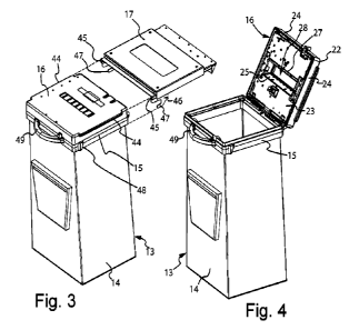
Fig.3 represents an exploded view of the two main com-
ponents of the system for coupling the bag to the ma-
chine according to the invention.
Fig.4 represents a view of the bag container with the
lid in an open position for complete accessibility into
the bag.
Fig.5 represents a view similar to that of Fig.4 but
with the lid in a closed position.
Fig.6 shows a view from below of the bag-holding frame.
Fig.7 shows, at the rear, the upper portion of the bag
container, with the rigid mouth intended to be fixed on
the bag-holding frame and the lid in a closed position.
Fig.8 shows, at the front, the upper portion of the bag
CA 03147688 2022-2-10
WO 2021/044352
PCT/11112020/058234
- 7 -
container in the same configuration of Fig.7.
Figures 9 and 10 show a detail of the security closing
means of the lid of the bag container.
Figures 11 and 12 show a detail of the rear security
means of the lid of the bag container.
Referring to the figures, in Fig.1 it is shown a por-
tion of the banknote handling and storing machine, more
specifically the safe 11 (represented "in transparency"
to make the inside visible) with its door 12 openable,
by known lock means, to have access inside the safe
and, in particular, for inserting and extracting the
bag container 13.
The remaining parts of the machine are not represented
herein, as it can be any type of machine for handing
and storing banknotes normally present in various trade
areas, banks, etcetera, e.g. machines able to receive
and dispense banknotes or other paper valuables, or ma-
chines only suitable to receive and store banknotes.
The bag container 13 inside the machine basically cam-
prises three main components, i.e. a flexible bag 14,
suitable to be filled with banknotes coming from han-
dling and conveying devices inside the machine, a gen-
erally rectangular-shaped upper rigid mouth 15, serving
as a frame for permanently fixing and supporting the
bag 14, and a lid 16 suitable to close the bag contain-
er 13, as will be hereinafter explained in greater de-
tail.
In particular, the lid 16 is hinged to the rigid mouth
15 of the bag container 13, such as to rotate between
an opened position (shown in Fig.4), of total access to
the inside of the bag container 13 by an operator, and
a closed position (shown in Fig.5), suitable to close
CA 03147688 2022-2-10
WO 2021/044352
PCT/11112020/058234
-8-
said rigid mouth 15 and, consequently, the bag 14 how-
ever enabling, during the filling operation inside the
machine, the only passage of banknotes entering the bag
14, as will be hereinafter explained in greater detail.
The bag container 13 is of the re-usable type, i.e. a
bag that can be closed and re-opened, so that it can be
used more than once, repeating the cycle of inserting,
in an empty condition, into the safe, filling with
banknotes by the machine, removing from the machine and
transferring towards a place for storing or reusing
banknotes.
The bag 14 is made of flexible material, for instance
"canvas", so as to be light, while also sufficiently
strong, and foldable to minimize its size when it is
not used.
In Fig.!, a bag-holding frame 17 is also visible, sta-
bly fixed to the structure of the safe 11, which is for
supporting and keeping the bag container 13 hooked when
placed inside the banknote handling and storing ma-
chine. Advantageously, the bag-holding frame 17 has a
perimeter conformation substantially corresponding to
that of the rigid mouth 15 and of the lid 16 of the bag
container 13, so as to optimise the support of the con-
tainer as much as possible.
The system for coupling the bag container 13 to the ma-
chine according to the invention thus basically com-
prises two components, well visible in a mutually sepa-
rated condition in Fig.3:
- the bag container 13, comprised of the upper rigid
mouth 15, of the flexible bag 14 permanently fixed to
the aforesaid rigid mouth and of the lid 16 hinged to
the rigid mouth 15;
CA 03147688 2022-2-10
WO 2021/044352
PCT/1112020/058234
-9-
- the bag-holding frame 17, suitable for being stably
fixed to the safe structure of the machine, which is
for supporting and keeping the bag container 13
hooked when placed inside the machine to be filled
5 with banknotes.
The system for coupling the bag container 13 to the ma-
chine according to the invention further provides cou-
pling and hooking electromechanical means between the
bag container 13 and the bag-holding frame 17.
In particular, referring to Figures 6-7, said coupling
and hooking electromechanical means between the bag
container 13 and the bag-holding frame 17 comprise an
electro-actuated lock 18 advantageously arranged on the
rear portion of the bag-holding frame 17 and facing to-
wards the front part thereof.
The terms "front" and "rear" herein mean respectively a
part (of the bag, of the lid or of the bag-holding
frame) closer to the access opening from outside into
the safe (at the door 12 visible in Fig.1) and a part
more distant from said opening.
Said coupling and hooking electromechanical means be-
tween the bag container 13 and the bag-holding frame 17
further comprise a blocking element 19 (advantageously
in the form of cylindrical pin) arranged on the rear
portion of the bag container 13 and projecting rear-
wardly therefrom in correspondence of said electro-
actuated lock 18 to engage and block therein when the
bag container 13 is correctly coupled to the bag-
holding frame 17 inside the safe 11 in the position il-
30 lustrated in Fig.l.
Of course, the blocking element 19 may also be made in
a shape other than a cylindrical pin, depending on the
CA 03147688 2022-2-10
WO 2021/044352
PCT/11112020/058234
- 10 -
type and configuration of the lock 18 used in the spe-
cific case.
A micro-switch (not visible in the enclosed drawings)
is advantageously associated with said electro-actuated
lock 18, for example housed inside its structure, which
detects the presence and the correct insertion and
blocking of the bag container 13 in the bag-holding
frame 17 and sends to a control unit 50 (schematically
represented in Fig.1) a signal of presence and correct
blocking of the bag container 13 on the bag-holding
frame 17 ("bag inserted" signal).
Said coupling and hooking electro-mechanical means be-
tween the bag container 13 and the bag-holding frame 17
further comprise a first electric connector 20 advanta-
geously arranged on the rear portion of the bag-holding
frame 17, facing towards the front part thereof, and a
second electric connector 21 arranged on the rear por-
tion of the bag container 13 in correspondence of said
first electric connector 20 to realize an electrical
connection between the bag container 13, the bag-
holding frame 17 and the control unit 50 when the bag
container 13 is positioned on the bag-holding frame 17.
The pin 19 and the electric connection 21 are advanta-
geously arranged on the rear portion of the lid 16,
above the hinging axis of the lid 16 to the upper rigid
mouth 15, so as to ensure that coupling and hooking of
the bag container 13 to the bag-holding frame 17 only
occurs if the lid 16 is correctly arranged in the clos-
ing position of the bag 14.
According to the invention, the closing lid 16 of the
bag container 13 is provided with means adapted to al-
low, on command, the banknotes passing from the machine
CA 03147688 2022-2-10
WO 2021/044352
PC T/H12020/058234
- 11 -
t o the bag 14 through the lid itself which, as seen,
must be placed in a closing position when the bag con-
tainer 13 is inserted correctly inside the machine.
In order to do so, the lid 16 has a double-wall struc-
ture, with an outer cover 22 intended to form an upper
wall of the bag container 13 when it is in a closed
condition, and an inner bottom 23, spaced from the out-
er cover 22 and destined to face the inner space of the
bag 14 when the lid 16 is closed.
Advantageously, the outer cover 22 is also provided
with side walls 24 for peripheral closure of the inter-
space 25 present between the cover itself and the inner
bottom 23 of the lid, so as to prevent any access at-
tempt to said interspace from outside.
As well visible in Figures 4 and 5, the outer cover 22
and the inner bottom 23 of the lid 16 are provided with
respective corresponding openings 26, 27 suitable to
identify a passage 28 for the banknotes entering the
bag 14, coming from the machine safe.
Inside the interspace 25 a movable element 29 is pre-
sent, suitable to alternatively realize, on command,
opening and closing of said passage 28.
In one preferred embodiment, said movable element 29
consists of a shutter sliding along a plane parallel to
the outer cover 22 and to the inner bottom 23 of the
lid 16, between an opening position (shown in the Fig-
ures 4 and 7) of the banknote passage 28 and a closing
position thereof (shown in the Figures 5 and 8).
An appropriate actuator 51 (for example an electric mo-
tor and related kinematic mechanisms) advantageously
housed inside the interspace 25 of the lid 16 is natu-
rally provided for the controlled movement of the shut-
CA 03147688 2022-2-10
WO 2021/044352
PCT/1112020/058234
- 12 -
ter 29. Said actuator is shown schematically in Figures
7 and 8, as it can be easily envisaged and realized by
the skilled in the art depending on the shape and size
of the movable parts and spaces available.
Advantageously always at the closing lid 16, there is
also an electronic board 52 (also schematically shown
in Figures 7 and 8), duly connected to the control unit
50 and to the actuator 51, for managing the opening and
closing of the shutter 29.
As it can be seen for example in Fig.6, the bag-holding
frame 17 is in turn provided with an opening 30 with
shape and size suitable to be located in correspondence
of the openings 26, 27 (and, therefore, of the relevant
passage 28) of the lid 16 when the bag container 13,
with the lid in closed position, is correctly inserted
inside the machine on the bag-holding frame 17.
As said, the bag container 13 can be inserted into the
machine only if its lid 16 is closed correctly on the
upper rigid mouth 15 supporting the bag 14.
The bag container 13 is further provided with security
closing means of the lid 16 on the upper rigid mouth 15
supporting the bag 14.
In the herein illustrated embodiment, said security
closing means of the lid 16 can be made by means of a
security seal 43 (schematically represented in Fig.5),
for example a self-blocking tie, that can be inserted
into a seat passing through the lid 16 and the upper
rigid mouth 15 of the bag container 13.
In particular, as visible in Figures 9 and 10, the seat
for inserting the security seal 43 consists of three
coaxial holes 31, 32, 33 respectively passing through a
first portion 34 of the lid 16, through a second por-
CA 03147688 2022-2-10
WO 2021/044352
PCT/11112020/058234
- 13 -
tion 35 of the upper rigid mouth 15 and through a mova-
ble hook 36 for locking and unlocking the lid, sliding
transversely between said first and second portions 34,
35 as schematically illustrated by the arrow 37 in Fig-
ures 9 and 10.
Advantageously, said first and second portions 34, 35
are portions protruding forwardly respectively from the
lid 16 and from the upper rigid mouth 15.
As it can be seen, the security seal 43 opposes trans-
versally to the opening motion of the hook 36 and, con-
sequently, it provides a high security against a forced
opening of the bag container even when the seal has not
been perfectly tightened.
A further degree of security against undue opening at-
tempts of the bag container is provided by the "anti-
unhooking" security system at the rear part of the con-
tainer.
In particular, as visible in Figures 11 and 12, at the
hinging rear edge of the lid 16 (advantageously, stably
fixed to the rear peripheral wall 24 of the outer cover
22) hooks 38 are present having one end 39 folded and
inserted into corresponding eyelets 40 arranged on the
upper rigid mouth 15 of the bag container 13. As well
visible in particular in Fig.12, in case someone at-
tempts to tamper with the bag container by removing the
pin 41 that hinges the lid 16 to the upper rigid mouth
15 and by lifting the rear edge of the lid according to
arrow 42 of Fig.12, the removal of the lid would be
hindered as the aforesaid hooks 38 remain constrained
inside their respective eyelets 40.
The operations of inserting the bag container 13 into
the safe 11 and removing the container from the safe,
CA 03147688 2022-2-10
WO 2021/044352
PCT/11112020/058234
- 14 -
after being filled with the banknotes from the machine,
will now be described.
Inserting the bag into the safe.
In order to insert the bag container 13 into the safe
11 it is firstly necessary to close the lid 16 on the
upper rigid mouth 15 supporting the bag 14 and to apply
the security seal 43 of the lid 16, inserting it
through the seat 31, 32, 33 and blocking the opening
hook 36. Thereby, the bag container 13 is completely
closed, as the shutter 29, as we will see, can be
opened only if the bag container 13 is correctly in-
serted and blocked in the bag-holding frame 17 of the
machine.
After that, starting from the condition illustrated in
Fig.3, the bag container 13 can be introduced into the
safe 11, inserting the side protrusions 44 of the lid
16 in the grooved guides 45 of the bag-holding frame 17
until engagement of the blocking element 19 in the
electro-actuated lock 18 provided on the rear portion
of the bag-holding frame 17. The bag container 13 is
now in the condition illustrated in Fig.l.
The presence and the correct blocking of the bag con-
tainer 13 on the bag-holding frame 17 are signalled to
the control unit 50 by the micro-switch associated to
the electro-actuated lock 18, which sends to the con-
trol unit a signal of presence and correct blocking of
the bag container 13 on the bag-holding frame 17 ("bag
inserted" signal) through the electric connection be-
tween the connector 20 arranged on the bag-holding
frame 17 and the electric connector 21 provided on the
bag container 13.
Communications between the control unit 50 and the bag
CA 03147688 2022-2-10
WO 2021/044352
PCT/11112020/058234
- 15 -
container 13 (and, in particular, the electronic board
52 on the lid 16) are advantageously made according to
encrypted protocols, as the person skilled in the art
can easily imagine.
The control unit 50, once received the "bag inserted"
signal, is set to allow the controlled opening and
closing of the shutter 29, by means of the relevant ac-
tuator 51, to enable inserting of the banknotes into
the bag.
Depending on the desired modes of managing the machine,
opening and closing the shutter 29 can be carried out
every time one or more banknotes must be inserted into
the bag, or one can choose to open the shutter 29 once
the bag container 13 is inserted into the machine, al-
ways keeping it opened and closing it only before re-
moving the container itself from the machine.
Removing the bag from the safe.
Before removing the bag container 13 from the safe 11,
the control unit 50 verifies that the shutter 29 is in
the closed position and, if such condition is verified
("shutter closed" signal), the control unit 50 can
send, via electric connection between the connector 20
provided on the bag-holding frame 17 and the electric
connector 21 provided on the bag container 13, an open-
ing control to the electro-actuated lock 18, disengag-
ing the lock element 19 and releasing the bag container
13, which can now be extracted from the safe 11 and
transferred, by an operator in charge of transporting
valuables, to a place for banknote storage or re-use.
Once the container is taken to a safe place, the secu-
rity seal 43 can be removed so that the lid 16 can be
completely opened to extract more easily the banknotes
CA 03147688 2022-2-10
WO 2021/044352
PCT/11112020/058234
- 16 -
contained in the bag.
It is now clear that the preset objects are reached by
the system for the safe coupling of a re-usable bag to
a banknote handling and storing machine according to
the invention.
In fact, the blocking of the bag container to the bag-
holding frame occurs thanks to the electro-actuated
lock 18, which does not allow the control unit 50 to
enable opening the shutter 29 (and thus to fill the
bag) until the "bag inserted" signal has been sent and
does not unlock the bag (for removing it from the ma-
chine) until it receives the "shutter closed" signal
from the control unit.
Clearly, the above description of an embodiment apply-
ing the innovative principles of the present invention
is given by way of an illustrative example of such in-
novative principles and must not, therefore, be taken
to limit the scope of the patent claimed herein.
For example, the movable element 29 suitable for alter-
natively opening and closing the banknote passage 28
may be made in the form of a door rotating inside the
interspace 25, instead of a sliding shutter.
Furthermore, the micro-switch associated to the elec-
tro-actuated lock 18 for detecting the presence and
correct insertion and locking of the bag container 13
into the bag-holding frame 17 may be placed in a physi-
cally different position with respect to said electro-
actuated lock 18, while being electrically connected
thereto.
As it can be observed from the enclosed drawings, it is
generally advantageous (for ease of construction and to
minimize the size of the bag-holding frame 17) to make
CA 03147688 2022-2-10
WO 2021/044352
PCT/11112020/058234
- 17 -
the guide protrusions 44 of the bag container 13 at the
outer cover 22 of the lid 16, i.e. at the upper end of
the container.
In that case, the bag container 13 would be constrained
to the bag-holding frame 17 (and thus to the safe 11)
only by the lid 16 and therefore only the sliding hook
36 and the security seal 43 would be in charge of keep-
ing the lid 16 closed relative to the upper rigid mouth
of the bag 14.
10 In order to guarantee a higher degree of security, pre-
venting the opening of the bag container (even in case
the seal 43 was removed) while the container is blocked
in the safe, the bag-holding frame can be provided (ad-
vantageously at the front ends of the grooved guides 45
15 thereof) with hook elements 46 having ends 47 suitable
to be inserted into corresponding seats 48 in the rigid
mouth 15 of the bag, as illustrated in greater detail
in Figures 6 and 7.
Thereby, both the lid 16 and the upper rigid mouth 15
remain constrained to the bag-holding frame 17 when the
bag container 13 is correctly inserted and blocked in-
side the machine.
Finally, the bag container 13 can also advantageously
comprise one or more handles 49 for easily transporting
the bag once removed from the machine.
CA 03147688 2022-2-10