Note: Descriptions are shown in the official language in which they were submitted.
¨ .
CA 03148715 2022-01-25 ¨ ¨
1
DESCRIPTION
Title
Cartridge system and method for producing a cartridge system
Prior art
The present invention proceeds from a cartridge system for producing a
beverage, wherein
the cartridge system is insertable into a beverage preparation machine, has a
cartridge com-
prising a reservoir filled with a beverage substance, and has a cartridge
receptacle con-
nected to the cartridge, wherein the cartridge receptacle has a mixing chamber
fluidly con-
nectable to the reservoir and a fluid feed opening into the mixing chamber.
Such systems are known from the prior art, for example, from the documents WO
2017 / 121
802 Al, WO 2017 / 121 801 Al , WO 2017 / 121 801 Al , WO 2017 / 121 799 Al ,
WO 2017 /
121 798 Al, WO 2017 / 121 797 Al, WO 2017 / 121 796 Al und WO 2019 / 002 293
Al and
are used to produce beverages from pre-portioned cartridges. The production of
beverages
with such systems is extremely convenient for the user, since he only has to
insert a car-
fridge and press a start button. The beverage preparation machine then takes
over making
the same in a fully automated manner, that is to say in particular that the
beverage sub-
stance is mixed with a predetermined amount of liquid, in particular cold and
carbonated wa-
ter, and is introduced into a drinking vessel. In this way, mixed beverages in
particular can be
produced much more easily, quickly and with little effort for the user. The
user can in this
case select from a large number of different cartridges, so that he can
produce different
drinks as desired.
A major challenge in such systems is to minimize the reference time, i.e. the
time required
from the start of the beverage production process by the user to produce the
finished bever-
age, in order to increase user convenience. Furthermore, another challenge is
to provide
sufficient beverage substance as well as sufficient carbon dioxide for a
beverage with an ap-
pealing taste, especially during this reference time to be minimized.
Summary of the invention
Date recue/ date received 2022-01-25
..--.-- -
CA 03148715 2022-01-25
.
Therefore, it is an object of the present invention to provide a cartridge
system for the pro-
duction of a beverage in a beverage preparation machine, in which the
production of a bever-
age with an appealing taste is achieved with a minimum of reference time.
This object is achieved by a cartridge system according to claim 1.
Compared with the prior art, the cartridge system according to the invention
has the ad-
vantage that the cartridge is not made of plastic but of aluminum. The
cartridge is therefore
much more stable and can withstand a higher internal pressure. The in
particular liquid bev-
3.0 erage substance can thus be enclosed in the reservoir under a
higher pressure without caus-
ing damage or deformation of the cartridge. It is thus possible to keep liquid
beverage sub-
stances with a higher carbon dioxide content in the reservoir without the risk
of the reservoir
bursting due to the carbon dioxide in the event of vibrations, for example
during transport or
storage of the cartridge system. The higher carbon dioxide content in turn has
a positive ef-
both on the taste of the beverage to be produced and on the best-before date
of the car-
tridge. Another advantage of the cartridge system according to the invention
is that the reser-
voir can be emptied at a higher pressure during the beverage production
process. This can
significantly reduce the time required for the beverage to be produced,
without the risk of im-
pairing the taste of the beverage. In order to achieve the desired stability,
the cartridge has a
main body made of aluminum, which in its typical wall region preferably has a
wall thickness
of between 0.01 and 0.5 millimeters, preferably between 0.01 and 0.2
millimeters, particularly
preferably between 0.03 and 0.1 millimeters and most preferably of essentially
0.05 millime-
ters, in particular with a defect tolerance of no more than 15%. The cartridge
is then prefera-
bly configured such that A can withstand an internal pressure of up to 10 bar,
particularly
preferably up to 8 bar and most preferably up to 6 bar without bursting (at a
temperature of
20 C and an external pressure of 1 bar). The reservoir thereby preferably
comprises a vol-
ume of between 10 and 500 milliliters, particularly preferably between 30 and
90 milliliters
and most preferably of substantially 60 milliliters. In particular, the
cartridge system com-
prises a liquid beverage substance which is preferably carbonated.
Particularly preferably,
the liquid beverage substance comprises a beverage concentrate, in particular
a syrup.
According to a preferred embodiment of the present invention, provision is
made for the car-
tridge to comprise a cup-shaped main body. The cup-shaped main body is
preferably pro-
duced by deep-drawing or impact extrusion, which advantageously enables
comparatively
inexpensive and rapid production. In particular, the cartridge is thus
necessarily hermetically
sealed on one side, whereby a particularly stable configuration of the
cartridge is realized.
Preferably, the main body is cup-shaped with a cylindrical cartridge wall,
which is closed on
Date recue/ date received 2022-01-25
..--.-- -
CA 03148715 2022-01-25
.
3
one side by a cartridge bottom, wherein the cartridge wall and the cartridge
bottom are
formed in particular in one piece. It is conceivable that the cartridge wall
and the cartridge
bottom consist of one piece and in particular both of aluminum, in that the
main body is deep-
drawn from a sheet of aluminum.
As an alternative to deep drawing or impact extrusion, the main body can also
be formed by
bending an aluminum sheet into a cylindrical tube and then bonding, welding
and/or pressing
the abutting sides of the aluminum sheet bent into the tube together to
produce a main body
with a longitudinal seam. In addition, the cartridge bottom is formed as a
separate lid body, in
particular by deep drawing or impact extrusion of a further aluminum sheet.
This cartridge
bottom, which is configured as a separate lid body, can then be slipped over
that end of the
cartridge wall which is bent towards the tube and faces away from the
cartridge receptacle,
and can there be circumferentially bonded, welded and/or pressed to the
cartridge wall. In
particular, the lid body is crimped onto the tubular cartridge wall to form
the cartridge bottom.
According to a preferred embodiment of the present invention, provision is
made for the main
body to be closed in its initial position on its side opposite the cartridge
bottom by a sealing
element. In a preferred manner, the sealing element ensures that the beverage
substance
remains within the reservoir before the start of the beverage production
process, where it is
hermetically sealed for long shelf life and consistent flavor.
According to a preferred embodiment of the present invention, provision is
made for the seal-
ing element to have a particularly rigid or semi-rigid sealing body with a pre-
punched hole. In
the area of the pre-punched hole, a partial area of the sealing body is
partially punched. This
means that the partial region is not completely punched from the sealing
element, but is only
partially punched, so that in the initial state of the cartridge it still
remains integrally con-
nected to the rest of the sealing element in its corner regions. Thus, the
reservoir 7 remains
hermetically sealed in the initial state. The sealing element here is in
particular the sealing
body made of aluminum. The size of the punched hole preferably corresponds
essentially to
the through-opening in the sealing element to be created later by the piercing
spike. Prefera-
bly, a predetermined breaking point is formed in an edge region of the partial
area by the par-
tial punched hole in relation to the rest of the sealing body, which tears
open at least partially
when the partial area comes into contact with a piercing spike of the beverage
preparation
machine (see below) in order to release the through-opening. Since the partial
area is
punched out of the sealing body, it has essentially the same size or diameter
as the through-
Date recue/ date received 2022-01-25
- .
CA 03148715 2022-01-25 .-
4
opening, in which the piercing spike is also arranged during beverage
production. This ad-
vantageously prevents the detached partial area from passing through the
through-opening
18' into the mixing chamber 8.
According to a further preferred embodiment of the present invention,
provision is made for
the sealing element to have an in particular rigid or semi-rigid sealing body
with a through-
opening. In particular, the sealing element is made of aluminum and is
attached to the main
body. It is conceivable for the sealing body to be crimped, bonded, clamped,
welded and/or
pressed to the main body. The through-opening is formed either centrally or
offset from the
center in the sealing body. The sealing body is thus disk-shaped and/or ring-
shaped. Alterna-
tively, it is conceivable for the sealing body also to be cup-shaped, with the
peripheral part
projecting from the cup bottom running parallel to the cartridge wall and
being pressed or
crimped to this part of the cartridge wall. In particular, the part projecting
from the cup base is
arranged on the inner side of the cartridge wall in order to give the
cartridge an aesthetically
pleasing outer appearance. In its typical wall region, the sealing body
preferably has a wall
thickness of between 0.09 and 0.5 millimeters, preferably between 0.1 and 0.3
millimeters,
particularly preferably between 0.15 and 0.25 millimeters and most preferably
of essentially
0.2 millimeters, in particular with a maximum defect tolerance of 15%.
According to a preferred embodiment of the present invention, provision is
made for the seal-
ing element to comprise a sealing foil which closes the through-opening in the
initial position
of the cartridge system, wherein the sealing foil is preferably a plastic
foil, an aluminum foil or
a multilayer foil made of plastic and/or aluminum. In this way, despite the
through-opening in
the sealing body, a hermetic seal of the reservoir is achieved, wherein during
the beverage
production process the sealing foil can be easily perforated by a piercing
spike (see below) of
the cartridge receptacle in order to transfer the beverage substance from the
reservoir into
the mixing chamber of the cartridge receptacle as quickly as possible.
Preferably, a circum-
ferential edge of the sealing foil is attached to the sealing element, in
particular bonded,
sealed and/or welded.
According to a preferred alternative embodiment of the present invention,
provision is made
for the sealing element to comprise a sealing foil, preferably a plastic foil,
an aluminum foil or
a multilayer foil made of plastic and/or aluminum, which is attached in
particular to the edge
of the cartridge wall. In this embodiment, the sealing element does not have
an additional
sealing body, but the opening of the main body is hermetically sealed directly
and in particu-
lar exclusively by the sealing foil, which is attached directly to the edge of
the cartridge wall.
Preferably, a circumferential peripheral fastening region of the sealing
element is crimped,
Date recue/ date received 2022-01-25
CA 03148715 2022-01-25
bonded, sealed and/or welded to the cartridge wall and in particular to the
edge of the car-
tridge wall.
It is conceivable for the fastening region to extend at least partially
parallel to the cartridge
wall on the inside or outside of the cartridge wall. In this case, the sealing
foil is also cup-
shaped or formed. It is conceivable for the sealing foil also to be deep-drawn
into this shape.
The sealing body of the sealing element could also be configured as a type of
crimp cap. It is
conceivable for the cartridge wall to comprise a circumferential rim around
which the sealing
body is crimped for attachment to the cartridge. Alternatively, the sealing
element could be
screwed onto the end of the cartridge. For this purpose, a fastening region of
the cartridge is
provided in particular with an external thread onto which the sealing body is
screwed. For this
purpose, the sealing body has in particular an internal thread complementary
to the external
thread. The screw connection is preferably adapted such that only screwing on
with subse-
latching is possible, so that subsequent unscrewing is prevented by the
latching.
According to a preferred alternative embodiment of the present invention,
provision is made
for a connecting means, in particular a latching bead, a latching bulge or an
undercut, to be
provided at the edge of the cartridge wall, in particular circumferentially,
for connecting the
cartridge to the sealing element and/or the cartridge receptacle. Preferably,
the sealing ele-
ment and/or the cartridge receptacle has a mating connecting means, in
particular a further
latching bead, a latching bulge or an undercut, which is in particular
complementary to the
connecting means and is connected to the connecting means in a form-fitting,
force-fitting
and/or material-fitting manner. Preferably, a stable and inexpensive
connection between the
cartridge and the cartridge receptacle and/or between the cartridge and the
sealing element
can thus be achieved.
According to a preferred alternative embodiment of the present invention,
provision is made
for the fastening region to be arranged at least partially between the
connecting means and
the mating connecting means, and in particular to be clamped, welded and/or
bonded in
place. in a preferred manner, the sealing element, in particular the edge of
the sealing body
or the edge of the sealing foil, is additionally fixed between the connecting
means and the
mating connecting means, i.e. from both sides, during the beverage production
process. A
comparatively large overpressure can thus be generated inside the reservoir
without the risk
of the sealing element detaching from the cartridge wall. Alternatively, it is
also conceivable
for the fastening region to be located on the inside of the cartridge wall, so
that the edge of
the cartridge wall is arranged between the fastening region and the cartridge
receptacle. in
Date recue/ date received 2022-01-25
- .
CA 03148715 2022-01-25 - ¨
6
this case, therefore, the connecting means is arranged between the fastening
means and the
mating connecting means. In this way, too, a particularly stable connection
can be achieved
between the main body, cartridge receptacle and sealing element. In addition,
the preferably
circumferential connecting means and/or mating connecting means of this
embodiment can
also be configured as a latching bead, latching bulge, undercut or the like.
It is particularly
preferred that both the fastening region of the sealing element and the edge
region of the
sealing foil are arranged between the connecting means and the mating
connecting means.
It is conceivable for the cartridge wall or sealing element to comprise a
circumferential rim
around which the wall of the cartridge receptacle is crimped.
Alternatively, the cartridge receptacle could be screwed onto the end of the
cartridge or onto
the sealing element. For this purpose, a fastening region of the cartridge or
the sealing ele-
ment is provided in particular with an external thread onto which the
cartridge receptacle is
screwed. For this purpose, the cartridge receptacle has an internal thread
complementary to
the external thread. The screw connection is preferably adapted such that only
screwing on
with subsequent latching is possible, so that subsequent unscrewing is
prevented by the
latching.
According to a preferred alternative embodiment of the present invention,
provision is made
for the cartridge receptacle to have a basic structure which is preferably
made at least par-
tially and in particular entirely of plastic. This advantageously achieves a
low-cost production.
In particular, the basic structure has a cup-shaped configuration the open
side of which is
aligned in the direction of the cartridge, wherein a beverage outlet opening
and an outwardly
open spike guide are formed on a bottom side opposite the cartridge, and
wherein a fluid
feed is formed on the bottom side or a side wall of the basic structure. This
cartridge recepta-
cle has the advantage that the fluid feed does not open into the reservoir of
the cartridge, but
into the mixing chamber separated from the reservoir. This prevents the fluid
feed from caus-
ing back contamination of the beverage preparation machine during the beverage
prepare-
tion process. For this purpose, the reservoir is not flushed by the fluid, but
rather the bever-
age substance and the fluid enter the mixing chamber of the cartridge
receptacle separately
from each other. The fluid is led directly into the mixing chamber, while the
beverage sub-
stance is transferred into the mixing chamber independently of the fluid. In
particular, a dis-
placeably mounted piercing spike is arranged within the spike guide for this
purpose, wherein
the piercing spike is displaceable between a retracted position, in which the
piercing spike is
spaced apart from the sealing element and in particular the sealing foil (or
the partial area),
Date recue/ date received 2022-01-25
- .
CA 03148715 2022-01-25 .-
7
and an extended position, in which the piercing spike pierces the sealing
element and in par-
ticular the sealing foil (or partially or completely tears off the partial
area from the sealing ele-
ment) and projects into the reservoir. In the initial state of the cartridge
system, the piercing
spike is thus in the retracted position so that the reservoir is hermetically
sealed by the seal-
ing element and, in particular, the sealing foil, and can be transferred from
the retracted posi-
tion to the extended position to open the sealing element of the cartridge. In
the extended po-
sition, the sealing element is perforated by the piercing spike or a pre-
punched hole is torn
open so that the beverage substance passes the sealing element through in
particular at
least one lateral channel on the piercing spike into the mixing chamber. Thus,
a simple and
reliable opening of a previously aroma-tight sealed cartridge in a beverage
preparation ma-
chine is made possible. In addition, it has been shown that back-contamination
of the bever-
age preparation machine is prevented, in particular because no overpressure
acting directly
on the fluid feed is generated in the reservoir. The configuration of the
mixing chamber in the
cartridge receptacle, which is reversibly insertable into the beverage
preparation machine,
advantageously ensures that the mixing chamber is part of the replaceable
cartridge system.
In this way, contamination of the beverage preparation machine by the beverage
substance
is effectively avoided because only parts of the replaceable disposable or
reusable cartridge
system come into contact with the beverage substance.
According to a preferred embodiment of the present invention, provision is
made for the car-
tridge system and in particular the cartridge receptacle to have at least one
support structure
which supports the sealing foil in the direction of the cartridge receptacle
and in particular in
the direction of the mixing cartridge. In this way, tearing of the sealing
foil is prevented, in
particular during pressure build-up in the reservoir during the beverage
production process.
The support structure comprises in particular a column-, bridge-, grid- or
cylinder-shaped
structure which projects from the bottom of the mixing chamber in the
direction of the reser-
voir and on which the sealing foil partially rests.
According to a preferred embodiment of the present invention, provision is
made for the
piercing spike to comprise a cylindrical or frustoconical base part and a
piercing part extend-
ing in the direction of the reservoir, wherein the piercing part is configured
in the form of an
obliquely cut truncated cone. Preferably, the piercing part is further
configured such that an
oblique cut surface of the obliquely cut truncated cone substantially faces
the reservoir,
wherein the oval periphery of the cut surface at least partially constitutes a
cut edge for per-
forating the sealing element. It has been shown that the cut surface, which is
generated by
an oblique cut through the truncated cone, on the one hand cuts the sealing
element easily
and with sufficiently little force, and on the other hand does not separate
any chips or loose
Date recue/ date received 2022-01-25
CA 03148715 2022-01-25 --
8
pieces from the sealing element, which would otherwise contaminate the
beverage in an un-
desirable manner. The sealing element perforation advantageously looks such
that on that
side of the piercing spike on which the maximum cutting edge projecting in the
direction of
the reservoir is formed, the material of the sealing element is cut with a
smooth cut, while in
the region of the cut surface of the piercing part the cut-off material of the
sealing element is
still connected to the remaining sealing element and is preferably rolled up
or folded.
Preferably, the piercing spike comprises an intermediate part arranged between
the base
part and the piercing part, which is frustoconical in shape, wherein a
circumferential shoulder
is formed between the base part and the intermediate part and wherein a
circumferential
edge is formed between the piercing part and the intermediate part.
Advantageously, a sta-
ble piercing spike is thus formed. The formation of the edge has the advantage
that the lat-
eral channels, insofar as they extend over the edge, have an enlarged entrance
on the reser-
voir side and thus the transfer of the beverage substance in the direction of
the mixing cham-
ber is facilitated. The shoulder serves to abut against a stop of the spike
guide when the
piercing spike is in the retracted position, thus limiting the extension
movement of the pierc-
ing spike in the direction of the cartridge.
According to a preferred embodiment of the present invention, provision is
made for the car-
tridge receptacle to have a plurality of lateral channels, wherein each
lateral channel extends
parallel to the piercing spike in the region of the piercing part and in the
region of the interme-
diate part. In this context, the lateral channels are each formed in
particular in the form of a
groove which is open on one side and is introduced into the outer surface of
the piercing
spike. Preferably, the lateral channels are at least partially formed in a
circumferential region
of the piercing spike that is rearward to the cut surface. This has the
advantage that the lat-
eral channels are arranged on the side of the sealing element perforation
where a cut has
been made in the material, and not on the opposite side where the cut material
is still con-
nected to the remaining sealing element. The beverage substance can thus flow
compara-
tively un-hindered into the lateral channels.
It is conceivable for the cross-section of the lateral channels and/or the
number of lateral
channels to be adapted to the viscosity of the beverage substance, so that the
lateral chan-
nels control or limit the flow of the beverage substance towards the mixing
chamber. At a
high viscosity, several lateral channels or lateral channels with a larger
cross-section are
used, while at a lower viscosity, fewer lateral channels or lateral channels
with a smaller
cross-section are provided. There is thus a suitable cartridge receptacle for
each cartridge.
Date recue/ date received 2022-01-25
- .
CA 03148715 2022-01-25 - ¨
9
According to a preferred embodiment of the present invention, provision is
made for the
piercing spike to have a twist prevention means in the form of a web
protruding radially from
the base part. Twisting of the piercing spike is thus advantageously avoided
while it is being
transferred from the retracted position into the extended position. It is also
ensured that the
lateral channels are arranged on that side of the piercing spike which faces
away from the
beverage outlet of the mixing chamber and in particular faces the fluid feed.
In this way, im-
proved mixing of the beverage substance and the fluid within the mixing
chamber is
achieved.
According to a preferred embodiment of the present invention, provision is
made for the
piercing spike to have an integrated compressed-air line, which is the
cartridge emptying de-
vice, wherein the compressed-air line extends along the piercing spike in
particular from a
first end of the piercing spike to a second end of the piercing spike, in this
way, three func-
tions are advantageously integrated into the piercing spike: 1. The piercing
spike comprises
the piercing part in order to perforate the sealing element and thus to open
the cartridge; 2.
The piercing spike comprises the lateral channels in order to allow the
beverage substance
to be transferred into the mixing chamber; 3. The piercing spike comprises the
integrated
compressed-air line in order to blow compressed air into the reservoir, with
the result that the
beverage substance is pushed into the mixing chamber under pressure.
Preferably, a compressed-air connection for connecting to a compressed-air
source is
formed at the second end, and a compressed-air outlet for blowing compressed
air into the
reservoir is formed at the first end. The cartridge emptying device integrated
into the car-
tridge receptacle thus comprises, within the meaning of the present invention,
first of all only
one compressed-air line, through which compressed air can be introduced into
the reservoir
from the outside. The cartridge receptacle is configured such that the
beverage substance is
pushed out of the reservoir into the mixing chamber by the compressed air. The
compressed
air is provided in particular by the beverage preparation machine. It is
conceivable for a com-
pressed-air source to be coupled directly to the compressed-air connection as
soon as the
cartridge system is inserted into the beverage preparation machine. This has
the advantage
that back-contamination in the direction of the beverage preparation machine
is effectively
avoided because the cartridge emptying device is immediately under pressure
when the car-
tridge system is inserted and thus beverage substance is prevented from
traveling in the di-
rection of the compressed-air line and in particular in the direction of the
compressed-air
source of the beverage preparation machine. The beverage substance can thus
move only in
the direction of the mixing chamber from the reservoir.
Date recue/ date received 2022-01-25
- .
CA 03148715 2022-01-25
According to a preferred embodiment of the present invention, provision is
made for the com-
pressed-air outlet to be configured as an opening in the cut face. This has
the advantage that
the air flowing into the reservoir is blown in on a side of the piercing spike
that is remote from
the lateral channels, such that the discharging of the beverage substance into
the mixing
5 chamber is not impeded. Preferably, a swirl thus forms in the reservoir,
this favoring virtually
residue-free emptying of the reservoir.
The compressed-air connection is configured in particular as an opening in the
base part,
wherein the base part is arranged in the cartridge receptacle such that the
compressed-air
10 connection is accessible from outside the cartridge receptacle. In this
way, the connection of
the compressed-air line to the compressed-air source is favored.
According to a preferred embodiment of the present invention, provision is
made for the
spike guide to have a guide part with an internal guide channel for receiving
the piercing
spike, wherein the guide channel of the guide part is configured in a
substantially cylindrical
or frustoconical manner, and wherein a circumferential stop is formed at an
end of the guide
part that faces the cartridge, said stop limiting the movement of the piercing
spike in the di-
rection of the reservoir, wherein the stop comprises in particular a region
with a reduced di-
ameter, in this way, reliable guiding of the piercing spike during the
movement from the re-
tracted position into the extended position is advantageously achieved.
Preferably, a groove
corresponding to the rib is formed as twist prevention means within the wall
of the guide
channel, such that undesired twisting of the piercing spike is prevented. The
guide part is
preferably arranged in the mixing chamber and protrudes from a bottom of the
mixing cham-
ber in the direction of the cartridge.
According to a preferred embodiment of the present invention, provision is
made for the
piercing spike to be configured as a plastic part and in particular as an
injection-molded plas-
tic part. This allows cost-effective production. In principle, however, it
would alternatively also
be conceivable to configure the piercing spike as a metal part.
According to a preferred embodiment of the present invention, provision is
made for the
piercing spike to be configured such that it is transferable from the
retracted position into the
extended position by a release element of the beverage preparation machine
when the car-
tridge system is inserted into the beverage preparation machine.
According to a further preferred embodiment of the present invention,
provision is made for
the mixing chamber to have a beverage outlet through which the beverage formed
from a
Date recue/ date received 2022-01-25
- .
CA 03148715 2022-01-25 - -
11
blend of the beverage substance with the fluid is discharged, wherein the
cartridge system is
preferably configured such that the beverage is able to be introduced directly
into a portable
vessel from the beverage outlet. Advantageously, therefore, neither the
beverage substance
nor the produced beverage comes into contact with any part of the beverage
preparation ma-
chine, and so any (back-)contamination of the beverage preparation machine is
more or less
avoided. The fluid is fed to the mixing chamber separately. Preferably, the
fluid is introduced
into the mixing chamber under pressure. The fluid is provided in particular by
the beverage
preparation machine. It is conceivable for a fluid source to be coupled
directly to a corre-
sponding fluid connection of the cartridge receptacle as soon as the cartridge
system is in-
serted into the beverage preparation machine. The fluid connection is in this
case fluidically
connected to the mixing chamber via a fluid line. This has the advantage that
back-contami-
nation in the direction of the beverage preparation machine is effectively
avoided because
the fluid connection is immediately under pressure when the cartridge system
is inserted and
thus beverage substance is prevented from traveling in the direction of the
fluid line and in
particular in the direction of the fluid source of the beverage preparation
machine. The bever-
age substance and the beverage can thus move only in the direction of the
beverage outlet
from the mixing chamber. The fluid comprises in particular water, preferably
pressurized,
cooled and/or carbonated drinking water.
According to a preferred embodiment of the present invention, provision is
made for the mix-
ing chamber to be provided with mixing structures. The mixing structures
advantageously en-
sure improved mixing of beverage substance and fluid. For this purpose, the
mixing struc-
tures are configured in particular such that the fluid flowing into the mixing
chamber is
swirled. It is conceivable for the mixing structure to comprise one or more
mixing ribs which
are arranged in the region of the fluid feed at the bottom of the mixing
chamber and extend
substantially perpendicular to the direction in which the fluid flows in. The
mixing ribs thus act
as barriers for the fluid, with the result that the fluid is swirled up and
better mixing with the
beverage substance is achieved.
According to a further preferred embodiment of the present invention,
provision is made for
the fluid feed to be supplied with fluid which is cooled by a refrigeration
unit, wherein the re-
frigeration unit is part of the beverage preparation machine or of a separate
refrigerator oper-
atively connected to the beverage preparation machine. Advantageously, it is
thus possible
for cold beverages to be produced even when the cartridge is not cooled and is
at room tern-
perature for example. The integration of the system into an existing
refrigerator has the ad-
vantage that the existing refrigeration unit of the refrigerator can be co-
used easily in an effi-
cient manner for the beverage preparation machine. In particular, in what are
known as
Date recue/ date received 2022-01-25
CA 03148715 2022-01-25 --
12
"side-by-side" refrigerators (often also referred to as American
refrigerators), sufficient instal-
lation space for integrating the system is found in the front. It is
conceivable for the beverage
preparation machine to be a retrofitting set for such a refrigerator. The
refrigeration unit com-
prises preferably a compressor cooling unit, an absorber cooling unit or a
thermoelectric
cooler.
According to a further preferred embodiment of the present invention,
provision is made for
the fluid feed to be supplied with fluid to which carbonic acid is added by a
carbonator. It is
conceivable for the carbonator to be part of the beverage preparation machine,
and wherein
the carbonator has a receptacle for a CO2 cartridge and a feeding device for
adding CO2
from the CO2 cartridge to the fluid. Advantageously, it is thus also possible
to produce car-
bonated soft drinks with the system. Alternatively, it would also be
conceivable for the car-
bonator to have an external CO2 connection.
A further subject matter of the present invention is a method for producing
the cartridge sys-
tem according to the invention, wherein in a first method step an aluminum
sheet is provided,
wherein in a second method step the main body is at least partially produced
from the sheet
by punching and deep drawing or impact extrusion, wherein in a third method
step a sealing
element is attached to the main body, and wherein in a fourth method step the
main body is
connected to the cartridge receptacle. The method according to the invention
enables a com-
paratively stable cartridge to be produced quickly and inexpensively, allowing
shorter refer-
ence times and higher carbon dioxide contents.
According to a further preferred embodiment of the present invention,
provision is made for
the cartridge receptacle to be manufactured by injection molding of plastic in
an intermediate
step carried out before the fourth method step. In a preferred manner, that
part of the car-
tridge system which is not subjected to high pressurization by the
introduction of compressed
air is thus manufactured in plastic by a low-cost manufacturing process,
whereby the overall
manufacturing costs can be kept low.
According to a further preferred embodiment of the present invention,
provision is made for a
piercing spike to be produced in a further intermediate step carried out
before or after the
fourth method step and to be inserted into a spike guide of the cartridge
receptacle.
According to a further preferred embodiment of the present invention,
provision is made for
the sealing element in the form of the sealing body to be punched and/or cut
out from an alu-
Date recue/ date received 2022-01-25
- .
CA 03148715 2022-01-25
13
minum sheet and/or from a sealing foil, preferably a plastic foil, an aluminum
foil or a multi-
layer foil made of plastic and/or aluminum, in a further intermediate step
carried out before
the third method step. If an aluminum sheet is used, in particular the sheet
is then deep-
drawn in the second method step such that the sealing body of the sealing
element formed
from the aluminum sheet preferably has a wall thickness in its typical wall
region of between
0.09 and 0.5 millimeter, preferably between 0.1 and 0.3 millimeter,
particularly preferably be-
tween 0.15 and 0.25 millimeter and very particularly preferably of essentially
0.2 millimeter, in
particular with a maximum error tolerance of 15%.
According to a further preferred embodiment of the present invention,
provision is made for
the partial area in the sealing body to be partially punched in the further
intermediate step in
order to form the pre-punching. The pre-punching thus defines the subsequent
through-
opening, which in the initial state is closed by the partial area still
connected to the remaining
sealing body and is only opened by the piercing spike immediately before or
during beverage
production.
According to a further preferred embodiment of the present invention,
provision is made for
the sealing element to be formed around an edge of the cartridge wall in a
further intermedi-
ate method step carried out before or during the third method step. This
forming can be car-
ried out both in the variant in which the sealing element comprises the
sealing body made of
a rigid or semi-rigid aluminum, and in the variant in which the sealing
element consists exclu-
sively of the sealing foil.
According to a further preferred embodiment of the present invention,
provision is made for
the sealing element to be crimped, bonded, sealed and/or welded to the edge of
the cartridge
wall during the third method step. In the variant in which the sealing element
comprises the
sealing body made of a rigid or semi-rigid aluminum, the sealing body is in
particular crimped
to the cartridge wall. In the variant in which the sealing element consists
exclusively of the
sealing foil, the sealing foil is in particular bonded, sealed and/or welded
to the cartridge wall.
According to a further preferred embodiment of the present invention,
provision is made for a
fastening region of the sealing element to be arranged between the edge of the
cartridge wall
and a part of the cartridge receptacle during the fourth method step and, in
particular, to be
clamped, welded and/or bonded in place. Preferably, the fastening region is
thus additionally
fastened by the connecting and mating connecting means.
Date recue/ date received 2022-01-25
- .
CA 03148715 2022-01-25 -
14
According to a further preferred embodiment of the present invention,
provision is made for a
through-opening to be created in the sealing element in a further intermediate
step, in partic-
ular for the through-opening to be drilled in the sealing element, and for the
through-opening
to be closed with a sealing foil in a later further intermediate step, wherein
the sealing foil is
preferably bonded, welded and/or sealed to the sealing element. This
embodiment relates to
the variant in which the sealing element comprises the sealing body made of a
rigid or semi-
rigid aluminum. This sealing body is provided with the through-opening, which
is closed in
the later intermediate step by the perforable sealing foil. This sealing foil
can be arranged
and fastened to the sealing body on the side of the mixing chamber or arranged
and fas-
3.0 tened to the sealing body on the side of the reservoir.
According to a further preferred embodiment of the present invention,
provision is made for a
connecting means, in particular a latching bead, a latching bulge or an
undercut, to be pro-
duced in the cartridge wall, in particular by forming, during or after the
second method step.
Furthermore, before the fourth method step and in particular during injection
molding of the
cartridge receptacle, a mating connecting means, in particular a latching
bead, a latching
bulge or an undercut, is then preferably produced on the cartridge receptacle.
In this way, it
is then optionally possible for a fastening region of the sealing element to
be arranged be-
tween the connecting means and the mating connecting means during the fourth
method
step and in particular to be clamped, welded in and/or bonded in.
The cup-shaped main body is preferably produced completely by deep drawing or
impact ex-
trusion in the second method step. Preferably, the main body is cup-shaped
with a cylindrical
cartridge wall which is closed on one side by a cartridge bottom, wherein the
cartridge wall
and the cartridge bottom are in particular formed in one piece. It is
conceivable that the car-
tridge wall and the cartridge bottom are made from one piece and in particular
both from alu-
minum, in that the main body is deep-drawn from a sheet of aluminum. As an
alternative to
deep drawing or impact extrusion, however, the main body can also be produced
only par-
tially by deep drawing or impact extrusion, in that an aluminum sheet is bent
to form a cylin-
drical tube and then the abutting sides of the aluminum sheet bent to form the
tube are
bonded, welded and/or pressed together, so that a main body with longitudinal
seam is pro-
duced, wherein the cartridge bottom is then additionally formed as a separate
lid body by
deep drawing or impact extrusion of a further aluminum sheet. This cartridge
bottom, which
is configured as a separate lid body, can then be slipped over that end of the
cartridge wall
which is bent towards the tube and faces away from the cartridge receptacle,
where it can be
circumferentially bonded, welded and/or pressed to the cartridge wall. In
particular, the lid
body is crimped onto the tubular cartridge wall to form the cartridge bottom.
Date recue/ date received 2022-01-25
CA 03148715 2022-01-25 ¨ ¨
is
Further details, features and advantages of the invention are apparent from
the drawings,
and from the following description of preferred embodiments with reference to
the drawings.
The drawings illustrate merely exemplary embodiments of the invention which do
not limit the
essential concept of the invention.
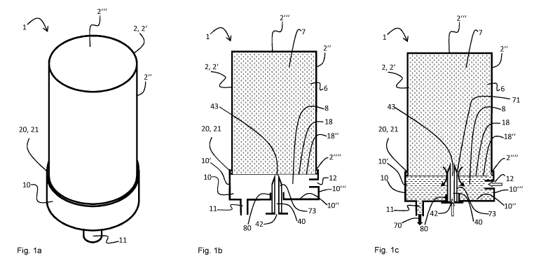
Brief description of the drawings
Figures la, lb und lc show a perspective view, a schematic sectional view
and the
general operating principle of a cartridge system according to
an exemplary first embodiment of the present invention.
Figure 2 shows a schematic sectional view of a cartridge
system accord-
ing to an exemplary second embodiment of the present inven-
Figures 3a und 3b show a schematic sectional view and the general
operating
principle of a cartridge system according to an exemplary third
embodiment of the present invention.
Figure 4 shows a schematic sectional view of a cartridge
system accord-
ing to an exemplary fourth embodiment of the present invention.
Figure 5 shows a schematic sectional view of a cartridge
system accord-
ing to an exemplary fifth embodiment of the present invention.
Figure 6 shows a schematic sectional view of a cartridge
system accord-
ing to an exemplary sixth embodiment of the present invention.
Figure 7 shows a schematic sectional view of a cartridge system accord-
ing to an exemplary seventh embodiment of the present inven-
tion.
Figures 8a und 8b show a perspective view and a schematic sectional
view of a
cartridge system according to an exemplary eighth embodiment
of the present invention.
Date recue/ date received 2022-01-25
..--.-- -
CA 03148715 2022-01-25
16
Embodiments of the invention
In the various figures, identical parts are always provided with the same
reference signs and
are therefore each generally also mentioned only once.
Figures la, lb and lc show a perspective view, a schematic sectional view and
the general
operating principle of a cartridge system 1 according to an exemplary first
embodiment of the
present invention.
The cartridge system 1 shown is provided to be inserted into a beverage
preparation ma-
chine (not shown) for preparing a beverage 70. For this purpose, the cartridge
system 1 has
a cartridge 2, which is filled with a particular beverage substance 7, and a
cartridge recepta-
cle 10 connected to the cartridge 2. Within the beverage preparation machine
3, a corre-
sponding beverage 70 is created with the aid of the beverage substance 7 and
an additional
water source, referred to as fluid source 41 in the following text. The
cartridge 2 is in this
case preferably filled with a pre-portioned quantity of beverage substance 7
which is neces-
sary for creating a specific drinking portion, for example a drinking glass
filling of the desired
beverage 70. The beverage substance 7 is in particular a liquid and carbonated
beverage
concentrate in the form of syrup.
In principle, a plurality of different cartridge systems 1 are available, the
cartridges 2 or reser-
voirs 6 of which are filled with different beverage substances 7 to produce
different bever-
ages 70. When the user of the system 1 wishes to drink a particular beverage
70, all he
needs to do is choose, from the plurality of different cartridge systems 1,
that cartridge sys-
tem 1 which contains the corresponding beverage substance 7 for producing the
desired
beverage 70, insert it into a retaining unit of the beverage preparation
machine and start the
beverage production process at the beverage preparation machine, for example
by pressing
a start button, by touching a touch sensitive display in an appropriate
manner, by gesture or
voice control, or by means of a suitable application on a cell phone. It is
also conceivable for
the beverage production process to start automatically when the insertion of a
new cartridge
system 1 into the retaining unit 90 is detected. In each of the abovementioned
cases, the de-
sired beverage 70 is then produced automatically, conveyed into a drinking
vessel and thus
provided to the user. Subsequently, the used-up cartridge system 1 is removed
and disposed
of. The beverage preparation machine 3 is now ready once again to be filled
with any desired
new cartridge system 1 in order to produce a further beverage 70.
Date recue/ date received 2022-01-25
- .
CA 03148715 2022-01-25 -
17
The beverage substance 7 comprises preferably liquid premixing constituents
for soft drinks,
such as caffeinated, carbonated, fruity and/or sugary sodas and juices, beer
(mixed) drinks,
or other alcoholic or nonalcoholic (mixed) drinks.
The cartridge system 1 comprises a cartridge 2 in the form of a cylindrical
container. The
container is hollow and thus contains a reservoir 6 for the beverage substance
7. The car-
tridge 2 is formed by a main body 2' made of aluminum, which is cup-shaped.
Cup-shaped
means here that the main body 2' has a cartridge bottom 2" (shown above in the
drawing)
and a cartridge wall 2" projecting at right angles from the cartridge bottom
2'" in the direction
of the cartridge receptacle 10. In this context, the cartridge wall 2" has a
cylindrical and cir-
cumferential configuration, while the cartridge bottom 2" in this example has
a circular and
disc-shaped configuration. The main body 2' is deep-drawn and punched out of
an aluminum
sheet during its manufacture (optionally first deep-drawn and then punched out
or vice
versa), so that the cartridge bottom 2" and the cartridge wall 2" are joined
together in one
piece.
On a side opposite the cartridge bottom 2" in the axial direction, the main
body 2' is closed
by a sealing element 18. In the first embodiment, the sealing element 18
comprises exclu-
sively a sealing foil 18", in particular a thin sealing foil, which closes the
reservoir 6 so that
the beverage substance 7 is sealed in an aroma-tight manner. For this purpose,
the outer cir-
cumferential edge region of the sealing element 18 is fixed circumferentially
to the edge 2"
of the cartridge wall 2". Preferably, the sealing element 18 is bonded, sealed
or welded here
to the edge 211" of the cartridge wall 2". In particular, the sealing foil 18"
comprises a plastic
foil, an aluminum foil or a multilayer foil made of plastic and/or aluminum.
The cartridge 2 is firmly or reversibly connected to the cartridge receptacle
10. The cartridge
receptacle 10 is connected to the cartridge receptacle 10 in particular after
the main body 2'
has been produced (deep drawing and punching or impact extrusion and
punching), after the
cartridge 2 has been filled with the beverage substance 7 and after the
reservoir 6 has been
closed by applying the sealing element 18. For this purpose, the cartridge
wall 2" optionally
has circumferential connecting means 20, in particular in the form of a
circumferential latch-
ing bead. The cartridge receptacle 10 optionally has mating connecting means
21 comple-
mentary to the connecting means 20, in particular in the form of a
circumferential latching
bulge, which latches into the latching bead when the cartridge 2 is connected
to the cartridge
receptacle 10. It is conceivable that the cartridge wall 2" and the cartridge
receptacle 10 are
additionally bonded, welded and/or pressed together.
Date recue/ date received 2022-01-25
- .
CA 03148715 2022-01-25
18
In its typical wall region, the main body 2' preferably has a wall thickness
of between 0.01
and 0.5 millimeters, preferably between 0.01 and 0.2 millimeters, particularly
preferably be-
tween 0.03 and 0.1 millimeters and most preferably of essentially 0.05
millimeters, in particu-
lar with a maximum error tolerance of 15%. The cartridge is then preferably
configured such
that it can withstand an internal pressure of up to 10 bar, particularly
preferably up to 8 bar
and most preferably up to 6 bar without bursting (at a temperature of 20 C and
an external
pressure of 1 bar). The cartridge 2 is then preferably configured such that it
can withstand an
internal pressure of up to 10 bar, particularly preferably up to 8 bar and
most preferably up to
6 bar without bursting (at a temperature of 20 C and an external pressure of
1 bar). The res-
ervoir 6 preferably has a volume of between 10 and 500 milliliters,
particularly preferably be-
tween 30 and 90 milliliters and most preferably essentially 60 milliliters.
The cartridge receptacle 10 has a mixing chamber 8 which is fluidically
connected to the res-
ervoir 6 during the beverage production process, such that, with the aid of a
cartridge empty-
device of the cartridge receptacle 10, the beverage substance 7 can be
transferred at
least partially out of the reservoir 6 into the mixing chamber 8. The
cartridge emptying device
to this end comprises a compressed-air line 40. One end of the compressed-air
line 40 is
connected to a compressed-air connection 42 which can be connected to a
compressed-air
source of the beverage preparation machine in order to introduce compressed
air into the
compressed-air line 40, while the other end leads into a compressed-air outlet
which is open
in the direction of the reservoir 6 and introduces compressed air into the
reservoir 6. The in-
troduction of the compressed air causes the beverage substance 7 to be pushed
into the
mixing chamber 8.
A fluid feed 12 of the cartridge receptacle 10, which is supplied by a fluid
source of the bever-
age preparation machine 3, also leads into the mixing chamber 8. It is
conceivable for the
fluid feed to have a quick coupling, by way of which the fluid feed 12 can be
connected to the
fluid source of the beverage preparation machine. The quick coupling can be
configured for
example such that, when the cartridge system 1 is inserted into the retaining
unit, a fluidic
connection is automatically established between the fluid source and the
mixing chamber 8
via the fluid feed 12. During the beverage production process, fluid, in
particular cooled and
carbonated drinking water, passes from the fluid feed 12 into the mixing
chamber 8 via this
fluidic connection. Furthermore, during the beverage production process,
beverage sub-
stance 7 passes from the reservoir 6 into the mixing chamber 8, as described
above. As a
result of the beverage substance 7 being blended with the fluid in the mixing
chamber 8, the
beverage 70 is formed, which then leaves the mixing chamber 8 through a
beverage outlet
11.
Date recue/ date received 2022-01-25
..--.-- -
CA 03148715 2022-01-25
19
The cartridge receptacle 10 has the beverage outlet 11, through which the
beverage 70 pro-
duced within the mixing chamber 8 leaves the mixing chamber 8, and is conveyed
in particu-
lar directly into the drinking vessel (not depicted), i.e. without parts of
the beverage prepare-
tion machine coming into contact with the beverage 70. In this way, back-
contamination of
the beverage preparation machine 3 is prevented. The drinking vessel is
arranged in particu-
lar directly beneath the beverage outlet 11,
Following completion of the beverage production process, the cartridge system
1 is removed
from the retaining unit, such that the beverage production machine can be
fitted with a new
and unused cartridge system 1. The cartridge receptacle 10 can optionally be
reused by be-
ing separated from the used cartridge 2 by releasing the latching connection,
and being clip-
fastened onto a new cartridge 2.
To establish the fluid connection between the reservoir 6 and the mixing
chamber 8, the car-
tridge receptacle 10 has a spike guide 80 in which a piercing spike 73 is
slidably mounted.
The sealing element 18 is perforated by the displaceable piercing spike 73
being transferred
between a retracted position, in which the piercing spike 73 is away from the
sealing element
18 (cf. figure 1b), and an extended position, in which the piercing spike 73
pierces the seal-
ing element 18 (cf. figure 1c) and projects into the reservoir 6.
The outer wall of the piercing spike 73 is provided with the plurality of
lateral channels 71 for
conveying the beverage substance 7 from the reservoir 6 in the direction of
the mixing cham-
ber 8 when the sealing element 18 is pierced. The lateral channels 71 are
configured in the
form of grooves that are open on one side and extend parallel to one another.
Following the
piercing of the sealing element 18, the lateral channels 71 become fluidically
connected to
the reservoir 6, such that the beverage substance 7 can flow around the edges
of the pierced
sealing element 18 in the direction of the mixing chamber 8.
The cross section of the lateral channels 71 and/or the number of the lateral
channels 71 is
in this case preferably adapted to the viscosity of the beverage substance 7,
such that the
lateral channels 71 control or limit the flow of the beverage substance 7 in
the direction of the
mixing chamber 8. At a high viscosity, a plurality of lateral channels 71
and/or lateral chan-
nels 71 with a relatively large cross section are used, while, at a lower
viscosity, fewer lateral
channels 71 and/or lateral channels 71 with a smaller cross section are
provided.
Date recue/ date received 2022-01-25
- .
CA 03148715 2022-01-25 .-
The piercing spike 73 also incorporates the compressed air line 40, which
functions as a car-
tridge emptying device. The compressed air line 40 opens into the reservoir 6
at the end of
the piercing spike 73 when the piercing spike 73 is in the extended position.
On a side of the piercing spike 73 facing away from the reservoir 6 in
particular, the corn-
5 pressed air connection 42 is formed, which can thus be accessed from
outside the cartridge
receptacle 10 and connected to the compressed air source of the beverage
preparation ma-
chine.
Preferably, the piercing spike 73 is transferred from the retracted position
to the extended po-
lo sition during or after insertion of the cartridge system 10 into the
beverage preparation ma-
chine or after starting the beverage production process, preferably by a
stationary release el-
ement of the retaining unit, against which the piercing spike 73 is pressed.
The piercing spike
71 is preferably a plastic part and particularly preferably a plastic
injection molded part.
15 Prevision is preferably made for both the fluid source and the
compressed-air source to be
coupled directly to the fluid feed 12 and to the compressed-air connection 42,
respectively,
as soon as the cartridge system 1 is inserted into the beverage preparation
machine or a
beverage production process is started, and in particular before the sealing
element 18 is
pierced. In this way, back-contamination in the direction of the beverage
preparation machine
20 is effectively avoided because the fluid feed 12 and the cartridge
emptying device are imme-
diately under overpressure upon insertion of the cartridge system 1, and this
prevents the
beverage substance 7 from traveling in the direction of the fluid source and
compressed-air
source, respectively. The beverage substance 7 can thus move only in the
direction of the
mixing chamber 8 from the reservoir 6 as soon as the sealing element 18 is
opened.
The cartridge receptacle 10 comprises a base structure 10' with a cup-shaped
configuration.
The open side of this cup-shaped configuration points towards the cartridge 2
and at least
partially receives the cartridge 2, in particular the edge 2¨ of the cartridge
wall 2". On an op-
posite bottom side 10", the base structure 10' has the beverage outlet opening
11 and the
outwardly open spike guide 80. The fluid feed 12 is formed on a side wall 10"
of the basic
structure 10'. The basic structure 10' is configured in particular as a
plastic part and espe-
cially preferably as a plastic injection-molded part.
Figure 2 shows a schematic sectional view of a cartridge system 1 according to
an exem-
Wary second embodiment of the present invention. The second embodiment is
similar to the
first embodiment illustrated and explained with reference to Figures la, lb
and lc, wherein,
Date recue/ date received 2022-01-25
- .
CA 03148715 2022-01-25 - ¨
21
in contrast, the cartridge receptacle 10 additionally has support structures
22 which support
the sealing foil 18".
In the present example, the support structures 22 comprise column and support-
like ele-
merits which extend from the bottom side 10" of the base structure 10' (in
particular within
the mixing chamber 8) in the direction of the reservoir 6 to such an extent
that the sealing foil
18' can be supported or rest on the elements and is protected from
unintentional tearing, in
particular during transport and storage of the cartridge system 1.
Figures 3a and 3b show a schematic sectional view and the general operating
principle of a
cartridge system 1 according to an exemplary third embodiment of the present
invention. The
third embodiment is similar to the first embodiment illustrated and explained
with reference to
Figures la, lb and lc, with the difference that the sealing element 18 does
not consist exclu-
sively of a sealing foil 18", but comprises a rigid or semi-rigid sealing body
18'", which is
made of aluminum.
The sealing body 18" has a through-opening 18', which in the initial state of
the cartridge sys-
tem I is in turn closed by a sealing foil 18" (see Figure 3a). The through-
opening 18' is ar-
ranged such that when the piercing spike 73 is transferred from the retracted
position to the
extended position, it protrudes through the through-opening 18', thereby
piercing the sealing
foil 18" (see Figure 3b). In particular, the piercing spike 73 does not come
into contact with
the sealing body 18". The sealing body 181" can therefore be very stable.
The sealing foil 18' in turn comprises a plastic foil, an aluminum foil or a
multilayer foil made
of plastic and/or aluminum, the circumferential edge of which is preferably
bonded, sealed
and/or welded to the sealing body 18-. The sealing foil 18' is arranged on
and/or fastened to
the sealing body 18- in particular on the outside of the sealing body 18-,
i.e. on the side fac-
ing the mixing chamber 8.
The sealing body 18" is preferably crimped with its edge region to the edge 2"
of the car-
tridge wall 2" in order to fasten the sealing body 18- to the main body 2'. It
is conceivable
that the cartridge wall 2" has a circumferential web at the edge 2" as a
connecting means
20, around which the sealing body 18- is crimped. The sealing body 18- thus
represents a
type of crimp cap.
Date recue/ date received 2022-01-25
- .
CA 03148715 2022-01-25
22
Alternatively, it is conceivable that the sealing body 18" is screwed to the
cartridge wall 2",
thus an internal thread of the sealing body 18" engages in an external thread
on the car-
tridge wall 2". The screw connection is preferably adapted such that only
screwing on with
subsequent latching is possible, so that subsequent unscrewing is prevented by
the latching.
Alternatively, it is conceivable that the edge of the cartridge wall 2" has a
connecting means
20, in particular a latching bead, a latching bulge or an undercut, for
connecting the cartridge
2 to the sealing body 18". Preferably, the sealing body 18" has a mating
connecting means
21 complementary to the connecting means 20, in particular a further latching
bead, a latch-
bulge or an undercut, which is connected to the connecting means 20 in a form-
fitting,
force-fitting and/or material-fitting manner.
In its typical wall region, the sealing body 18" preferably has a wall
thickness of between 0.09
and 0.5 millimeters, preferably between 0.1 and 0.3 millimeters, particularly
preferably be-
0.15 and 0.25 millimeters, and most preferably of essentially 0.2 millimeters,
in partic-
ular with a maximum error tolerance of 15%.
Figure 4 shows a schematic sectional view of a cartridge system 1 according to
an exem-
plary fourth embodiment of the present invention. The fourth embodiment is
similar to the first
embodiment illustrated and explained on the basis of Figures la, lb and lc,
wherein, in con-
trast to the third embodiment, the sealing foil 18" is not arranged on the
outside of the sealing
body 18"1, but wherein the sealing foil 18" is arranged and, in particular,
fastened on the in-
side of the sealing body 181" facing the reservoir 6.
The sealing foil 18' again comprises a plastic foil, an aluminum foil or a
multilayer foil made of
plastic and/or aluminum, the circumferential edge of which is preferably
bonded, sealed
and/or welded to the inside of the sealing body 18".
Figure 5 shows a schematic sectional view of a cartridge system 1 according to
an exem-
plary fifth embodiment of the present invention. The fifth embodiment is
similar to the third
embodiment illustrated and explained with reference to Figures 3a and 3b,
wherein, in con-
trast to the third embodiment, the sealing body 18" has a fastening region at
its edge.
This fastening region is angled at 90 degrees relative to the remaining region
of the sealing
body 18" and thus extends parallel to the cartridge wall 2". There is
therefore an overlap
area between the fastening region and the edge 2" of the cartridge wall 2".
The sealing body
18" is thus also cup-shaped. In the present example, the fastening region has
a slightly
Date recue/ date received 2022-01-25
..--.-- -
CA 03148715 2022-01-25
.
23
larger radius than the edge 2" of the cartridge wall 2", so that the fastening
region is ar-
ranged at least partially between the edge 2" of the cartridge wall 2" and the
edge of the car-
tridge receptacle 10.
The fastening region is arranged in particular between the connecting means 20
and the
mating connecting means 21 and is additionally fastened there, in particular
by bonding,
clamping, pressing, welding or the like.
In particular, the sealing body 18" is formed from the aluminum sheet into its
cup-shaped
3.0 configuration by deep drawing or impact extrusion.
It is conceivable that the cartridge wall 2" and the cartridge receptacle 10
also have the con-
necting and mating connecting means 20, 21. Alternatively, these connecting
and mating
connecting means 20, 21 are not realized.
Figure 6 shows a schematic sectional view of a cartridge system 1 according to
an exem-
plary sixth embodiment of the present invention. The sixth embodiment is
similar to the fourth
embodiment illustrated and explained with reference to Figure 5, wherein, in
contrast to the
fourth embodiment, the sealing body 18- has a smaller radius than the
cartridge wall 2".
The fastening region is thus arranged on the inside of the cartridge
receptacle 2", so that the
edge 2" of the cartridge receptacle 2" is arranged between the fastening
region and the
edge of the cartridge receptacle 10 and is fastened there, in particular by
bonding, clamping,
pressing, welding or the like.
It is conceivable for the cartridge wall 2" and the cartridge receptacle 10 to
also have the
connecting and mating connecting means 20, 21. Alternatively, these connecting
and mating
connecting means 20, 21 are not realized.
Figure 7 shows a schematic sectional view of a cartridge system 1 according to
an exem-
plary sixth embodiment of the present invention. The sixth embodiment is
similar to the fourth
embodiment illustrated and explained with reference to Figure 5, wherein, in
contrast to the
fourth embodiment, the sealing foil 18" extends to the fastening region.
Figures 8a and 8b show a perspective view and a schematic sectional view of a
cartridge
system 1 according to an exemplary eighth embodiment of the present invention.
The eighth
Date recue/ date received 2022-01-25
..--.-- -
CA 03148715 2022-01-25
.
24
embodiment is similar to the first embodiment illustrated and explained with
reference to Fig-
ures la, lb and 1 c, wherein, in contrast, the main body 2' is not
manufactured by a deep-
drawing process.
The main body 2' therefore also does not consist of a cartridge wall 2" and a
cartridge bottom
2", which are integrally connected to one another. In the eighth embodiment,
the main body
2' is formed by bending an aluminum sheet into a cylindrical tube. The
abutting sides of the
sheet bent into the tube are then bonded, welded or pressed together, forming
a longitudinal
seam 23.
In addition, the cartridge bottom 21" is formed as a separate lid body 24, in
particular by deep
drawing or impact extrusion of a further aluminum sheet. This cartridge bottom
21", formed as
a separate lid body 24, is then slipped over that end of the cartridge wall 2"
bent into the tube
which faces away from the cartridge receptacle 10, where it is
circumferentially bonded,
welded and/or pressed to the cartridge wall 2". In particular, the lid body 24
is crimped onto
the tubular cartridge wall 2" to form the cartridge bottom 2".
Depending on the embodiment of the sealing element, the subsequent
manufacturing steps
may optionally be carried out as in any of the other embodiments described
above (first to
seventh embodiments).
Figures 9a and 9b respectively show a schematic sectional view and a detailed
view of the
sealing element 18 of the cartridge system 1 according to an exemplary ninth
embodiment of
the present invention. The ninth embodiment is similar to the third embodiment
illustrated
and explained with reference to Figures 3a and 3b, although in contrast the
sealing element
18 does not comprise a sealing foil 18", but only comprises the sealing body
18". The sealing
body 18- is again rigid or semi-rigid and is made of aluminum.
The sealing body 18". has a pre-punched hole 27, in which a partial area 19 of
the sealing
body 18" is partially pre-punched out of the sealing body 18". However, this
partial area 19
is not completely punched out by the pre-punched hole 25, but only partially
punched out, so
that it still remains integrally connected to the remaining sealing body 18-
in its corner areas
and seals the reservoir 7 with respect to the mixing chamber 8. This initial
state (also referred
to as the delivery state of the cartridge) is illustrated in Figure 9a.
Due to the pre-punched hole 25 of the sealing element 18 or sealing body 18'",
the sealing
body 18." has a weakened or predetermined breaking point in the edge region of
the partial
Date recue/ date received 2022-01-25
CA 03148715 2022-01-25 - ¨
area 19. If now, before or during the beverage production, the piercing spike
73 hits the par-
tial area 19 and presses it in the direction of the reservoir 7, the
connection between the par-
tial area 19 and the remaining sealing body 19 at least partially tears or
collapses, whereby
the through-opening 18 is formed, in particular according to the size of the
pre-punched hole
5 25.
Due to the fact that the partial area 19 is punched out of the sealing body
18, it has essen-
tially the identical size or diameter as the through-opening 18, in which the
piercing spike 73
is additionally arranged during beverage production. This advantageously
prevents the de-
10 partial area 19 from passing through the through-opening 18' into the
mixing chamber
8.
Date recue/ date received 2022-01-25
..--.-- -
CA 03148715 2022-01-25
26
List of reference signs
1 Cartridge system
2 Cartridge
2 Main body
2" Cartridge wall
2"` Cartridge bottom
Edge of the cartridge wall
6 Reservoir
7 Beverage substance
8 Mixing chamber
10 Cartridge receptacle
10' Base structure
10" Bottom side
10¨ Side wall of the base structure
11 Beverage outlet
12 Fluid feed
18 Sealing element
18' Through-opening
18" Sealing foil
18¨ Sealing body
19 Partial area
20 Connecting means
21 Mating connecting means
22 Support structure
23 Longitudinal seam
24 Lid body
25 Pre-punched hole
40 Compressed-air line
42 Compressed-air connection
43 Compressed-air outlet
71 Lateral channel
70 Beverage
73 Piercing spike
80 Spike guide
Date recue/ date received 2022-01-25