Note: Descriptions are shown in the official language in which they were submitted.
CA 03148942 2022-01-27
WO 2021/028526
PCT/EP2020/072735
1
STORM WATER DRAIN PIT
Field of the invention
This invention relates to a storm water drain pit comprising a filter, a
method of making a filter, a method of installing a filter into a storm water
drain
pit, a filter for a storm water drain pit and use of a filter in a storm water
drain pit.
Background of the invention
Storm water (e.g. run off water from residential and commercial areas) is
collected and transported by storm water drain systems. Typically, the storm
water is channelled into the storm water system via storm water drain pits
i.e.
storm water drains in the ground, also called storm water gullies, catch
basins or
storm water inlets. Storm water drain systems typically have a number of storm
water drain pits, which lead to a network of underground drain pipes. The
storm
water is collected by the storm water drain pits, filtered to remove
particulates or
debris and then transported to a water storage area.
It is desirable to collect the particulates, pollutants and debris at the
initial
point of entry into the storm water drain system i.e. in the storm water drain
pit.
This is because it is necessary for the particulates, pollutants and debris,
which
have been removed via filtration, to be removed periodically from the drain
system in order to prevent blockage of the drainage and filtering system.
Typically, in order for the collection of particulates, pollutants and debris
to be
removed, it is necessary for an individual (e.g. a maintenance worker) to
first
remove the filter. This can be time-consuming as the storm water drain pit
must
be, in part, dismantled and then rebuilt.
The filters in storm water drain pits must be able to remove large amounts
of particulates, pollutants and debris from storm water. They must also be
easily
serviced and maintained, as it is necessary to remove the filtered debris
periodically. Furthermore, the filters must be capable of being held securely
in
place within the storm water drain pit, so as not to be dislodged by heavy
flows
of storm water.
US 2014/0374332 Al discloses a filtration apparatus for removing
particulates and contaminants from storm water run-off. The filtration
apparatus
comprises a collapsible frame for supporting a filter bag. The filter bag may
be
formed of a mesh, such as glass fibre mesh.
CA 03148942 2022-01-27
WO 2021/028526
PCT/EP2020/072735
2
US 6,093,314 A discloses a drain insert for a storm water sewer system
which prevents sand, gravel and petroleum products from entering the storm
water removal system. The drain insert comprises a filter element which is
formed of geotextile material and is supported by a pair of hooks. In order
for
debris which has been collected to be removed, the entire drain insert is
removed from the storm water sewer system.
US 6,517,709 B1 discloses a filter assembly for a catch basin erosion
containment. The filter assembly contains a rigid frame and a containment bag
formed of woven and non-woven geotextile fabric.
US 2009/0173699 Al discloses a filter for a storm drain system. The
filter is made of flexible material and is configured to be suspended within a
catch basin, so that it is easy to install and remove for cleaning.
US 2009/0045128 Al discloses an elongated filterable element used for
removing sediment in storm water. The filtering element contains a support
member, a filter mat, which can be made of fibreglass fibres, and an outer
casing.
US 2009/0277820 Al discloses a filtering device for storm water run-off.
It contains a removable frame and a filtering component, which may be made
from fiberglass.
It would be desirable to produce a filter for a storm water drain pit which is
self-supporting and rigid. It would be desirable to produce a filter for a
storm
water drain pit which does not need to be removed when the storm water drain
pit is being cleaned i.e. when the collected debris is removed by a storm
water
drain pit emptier or sludge exhauster. It would be desirable to produce a
filter for
a storm water drain pit which has a longer life span than existing filters. It
would
be desirable to produce a filtering system for a storm water drain pit which
has
equivalent or improved filtration in comparison to existing filtering systems
i.e.
can remove the same or more pollutants, contaminants, particulates and debris,
while also being less likely to get clogged or blocked. It would be desirable
to
produce a filter for a storm water drain pit which is hydrophilic.
Furthermore, it
would be desirable to produce a filter and filter system for a storm water
drain pit
which is environmentally acceptable and economical in terms of production,
installation and use. The present invention solves these problems.
CA 03148942 2022-01-27
WO 2021/028526
PCT/EP2020/072735
3
Summary of the invention
In a first aspect of the invention, there is disclosed a storm water drain pit
comprising:
an inlet for storm water;
a filter for removing particles from the storm water, comprising a cylindrical
body
comprising coherent man-made vitreous fibres (MMVF) bonded with a cured
binder composition; wherein the cylindrical body has a hollow centre and an
outer wall;
a guide element for guiding water from the inlet into the cylindrical body;
a sedimentation chamber for sedimentation of particles from the storm water,
wherein the cylindrical body is positioned below the inlet and above the
sedimentation chamber;
an outlet for filtered water; wherein the outlet is positioned above the
sedimentation chamber and below the inlet; and
a separation element for separating the sedimentation chamber from the outlet;
wherein the cylindrical body has a density in the range of 50 to 200 kg/m3, a
binder content in the range of 2 to 5 wt% and the outer wall has a
circumferential
thickness in the range of 2 cm to 20 cm.
In a second aspect of the invention, there is disclosed a filter for a storm
water drain pit, comprising:
a cylindrical body comprising coherent man-made vitreous fibres (MMVF)
bonded with a cured binder composition; wherein the cylindrical body has a
hollow centre and an outer wall;
wherein the cylindrical body has a density in the range of 50 to 200 kg/m3, a
binder content in the range of 2 to 5 wt% and the outer wall has a
circumferential
thickness in the range of 2 cm to 20 cm.
In a third aspect of the invention, there is disclosed use of a filter for
removing particulates from storm water, wherein the filter comprises:
a cylindrical body comprising man-made vitreous fibres (MMVF) bonded with a
cured binder composition; wherein the cylindrical body has a hollow centre and
an outer wall;
CA 03148942 2022-01-27
WO 2021/028526
PCT/EP2020/072735
4
wherein the cylindrical body has a density in the range of 50 to 200 kg/m3, a
binder content in the range of 2 to 5 wt% and the outer wall has a
circumferential
thickness in the range of 2 cm to 20 cm.
In a fourth aspect of the invention, there is disclosed a method of
installing a filter into a storm water drain pit, comprising the steps:
inserting a filter into a storm water drain pit; wherein the filter
comprises a cylindrical body comprising coherent man-made
vitreous fibres (MMVF) bonded with a cured binder composition;
wherein the cylindrical body has a hollow centre and an outer wall;
wherein the cylindrical body has a density in the range of 50 to
200 kg/m3, a binder content in the range of 2 to 5 wt% and the
outer wall has a circumferential thickness in the range of 2 cm to
cm.
In a fifth aspect of the invention, there is disclosed a method of emptying
15 a storm water drain pit according to the present invention, comprising
the steps:
inserting a storm water drain pit extractor through the inlet and the hollow
centre
of the cylindrical body, and into the sedimentation chamber;
using the storm water drain pit extractor to remove sediment in the
sedimentation chamber; and
20 removing the storm water drain pit extractor from the sedimentation
chamber,
hollow centre of the cylindrical body and the inlet.
In a sixth aspect of the invention, there is disclosed a storm water drain
pit liner comprising:
a housing comprising;
an inlet for storm water;
a filter for removing particles from the storm water, comprising a cylindrical
body
comprising coherent man-made vitreous fibres (MMVF) bonded with a cured
binder composition; wherein the cylindrical body has a hollow centre and an
outer wall;
a guide element for guiding water from the inlet into the cylindrical body;
a sedimentation chamber for sedimentation of particles from the storm water,
wherein the cylindrical body is positioned below the inlet and above the
sedimentation chamber;
CA 03148942 2022-01-27
WO 2021/028526
PCT/EP2020/072735
an outlet for filtered water; wherein the outlet is positioned above the
sedimentation chamber and below the inlet; and
a separation element for separating the sedimentation chamber from the outlet;
wherein the cylindrical body has a density in the range of 50 to 200 kg/m3, a
5 binder
content in the range of 2 to 5 wt% and the outer wall has a circumferential
thickness in the range of 2 cm to 20 cm.
Brief description of figures
Figure 1 shows a filter for a storm water drain pit according to the present
invention.
Figure 2 shows a storm water drain pit according to the present invention.
Figure 3 shows the results of water permeability tests.
Detailed description
The invention relates to a storm water drain pit comprising an inlet for
storm water; a filter; a sedimentation chamber and an outlet for filtered
water. A
storm water drain pit is an underground drain system in which storm water is
filtered and channelled into the storm water system. The filtered water is
transported to a water collection point. Storm water drain pits are also
called
storm water drains in the ground, gullies, catch basins or storm water inlets.
Typically a storm water drain pit is reached via a permeable grid in the
ground
i.e. a gridded drain cover. A storm water drain system typically includes
multiple
storm water drain pits.
The filter according to the present invention comprises a cylindrical body.
The term cylindrical has its usual meaning in the art i.e. shaped like a
cylinder. It
has an upper circular face and a lower circular face and an outer wall which
joins
the upper circular face to a lower circular face. The cylindrical body has a
circular cross-section. The cylindrical body has a hollow centre. By this, it
is
meant that the cylindrical body has a hollow section which extends from the
upper circular face to the lower circular face. The cylindrical body having a
hollow centre is pipe-shaped. The cylindrical body has an outer diameter, an
inner diameter and a circumferential thickness, due to the hollow centre. The
advantage of a filter comprising a cylindrical body with a hollow centre is
that it
does not need to be removed during maintenance and cleaning of the storm
water drain pit. Advantageously, the pipes/vacuums used for removing debris
from storm water drain pits can be inserted through the hollow centre of the
filter.
CA 03148942 2022-01-27
WO 2021/028526
PCT/EP2020/072735
6
Due to the pipe-shaped filter of the present invention, the storm water drain
pit
can be cleaned without the need to remove the filter. This means that
maintenance and cleaning are more efficient and less time-consuming.
The cylindrical body of the filter comprises coherent man-made vitreous
.. fibres (MMVF) bonded with a cured binder composition. The man-made vitreous
fibres (MMVF) can be glass fibres, ceramic fibres, basalt fibres, slag wool,
stone
wool and others, but are usually stone wool fibres. Stone wool generally has a
content of iron oxide at least 3% and content of alkaline earth metals
(calcium
oxide and magnesium oxide) from 10 to 40 %, along with the other usual oxide
constituents of MMVF. These are silica; alumina; alkali metals (sodium oxide
and potassium oxide) which are usually present in low amounts; and can also
include titania and other minor oxides. Fibre diameter is often in the range
of 3
to 20 pm, preferably 3 to 5 pm.
The filter according to the present invention is preferably in the form of a
coherent mass of MMVF i.e. a MMVF substrate. That is, the filter is generally
a
coherent matrix of MMVF fibres bonded with a cured binder composition, which
has been produced as such, or has been formed by granulating a slab of MMVF
and consolidating the granulated material.
The filter according to the present invention comprises a cylindrical body
that is self-supporting in use. By this, it is meant that the cylindrical body
is rigid
and capable of staying upright or in position without the use of a support.
The
filter according to the present invention is upright in use, by this it is
meant that
the lower circular face is positioned on a surface, and the upper circular
face is
exposed. Storm water to be filtered passes through hollow centre of the
cylindrical body, via the upper circular face, and is filtered to remove
particulates.
The storm water passes through the side walls of the cylindrical body but
particulates are prevented from passing through the side walls. The
cylindrical
body is rigid and self-supporting due to the binder content, density of the
MMVF,
and circumferential thickness of the outer wall. This is discussed in more
detail
below. The rigidity can be defined as a range of water pressure the
cylindrical
body can withstand. Preferably, the hollow centre of the cylindrical body can
withstand being fully filled with water, with no water at the circumference of
the
filter. Preferably, the cyclindrical body can withstand pressures of up to 0.1
atm,
CA 03148942 2022-01-27
WO 2021/028526
PCT/EP2020/072735
7
more preferably up to 0.5 atm. In such an embodiment, the water pressure is
equivalent to the height of the cylindrical body.
The filter according to the present invention comprises man-made
vitreous fibres bonded with a binder. The binder is present in the range of 2
to 5
wt%, preferably 3 to 4 wt%. This ensures that the filter according to the
present
invention is rigid and self-supporting in the sense that it can remain upright
when
positioned in use.
The binder can be an organic hydrophobic binder, and in particular it can
be a conventional heat-curable (thermosetting), binder of the type which has
been used for many years in MMVF substrates (and other MMVF-based
products). This has the advantage of convenience and economy. Thus, the
binder is preferably a phenol formaldehyde resin or urea formaldehyde resin,
in
particular phenol urea formaldehyde (PUF) resin.
The binder may be a formaldehyde-free aqueous binder composition
comprising: a binder component (A) obtainable by reacting at least one
alkanolamine with at least one carboxylic anhydride and, optionally, treating
the
reaction product with a base; and a binder component (B) which comprises at
least one carbohydrate, as disclosed in W02004/007615. Binders of this type
are hydrophilic.
W097/07664 discloses a hydrophilic substrate that obtains its hydrophilic
properties from the use of a furan resin as a binder. Binders of this type may
be
used in the present invention.
W007129202 discloses a hydrophilic curable aqueous composition
wherein said curable aqueous composition is formed in a process comprising
combining the following components:
(a) a hydroxy-containing polymer,
(b) a multi-functional crosslinking agent which is at least one selected
from the group consisting of a polyacid, salt(s) thereof and an anhydride, and
(c) a hydrophilic modifier;
wherein the ratio of (a):(b) is from 95:5 to about 35:65.
The hydrophilic modifier can be a sugar alcohol, monosaccharide,
disaccharide or oligosaccharide. Examples given include glycerol, sorbitol,
glucose, fructose, sucrose, maltose, lactose, glucose syrup and fructose
syrup.
Binders of this type can be used in the present invention.
CA 03148942 2022-01-27
WO 2021/028526
PCT/EP2020/072735
8
Further, a binder composition comprising:
a) a sugar component, and
b) a reaction product of a polycarboxylic acid component and an
alkanolamine component,
wherein the binder composition prior to curing contains at least 42% by
weight of the sugar component based on the total weight (dry matter) of the
binder components may be used in the present invention.
The binder may be as described in WO 2017/114724, wherein the binder
composition prior to curing comprises the following components:
a component (i) in the form of one or more compounds selected from
- compounds of the formula, and any salts thereof:
HO OH
in which R1 corresponds to H, alkyl, monohydroxyalkyl, dihydroxyalkyl,
polyhydroxyalkyl, alkylene, alkoxy, amine;
- compounds of the formula, and any salts thereof:
0 0
in which R2 corresponds to H, alkyl, monohydroxyalkyl, dihydroxyalkyl,
polyhydroxyalkyl, alkylene, alkoxy, amine;
a component (ii) in the form of one or more compounds selected from the group
of ammonia, amines or any salts thereof;
a component (iii) in the form of one or more carbohydrates.
The binder composition may be as described in WO 2017/114723
wherein the binder composition prior to curing comprises the following
components:
a component (i) in form of one or more carbohydrates;
CA 03148942 2022-01-27
WO 2021/028526
PCT/EP2020/072735
9
a component (ii) in form of one or more compounds selected from
sulfamic acid, derivatives of sulfamic acid or any salt thereof.
The binder composition may be a composition comprising at least on
hydrocolloid prior to curing. Preferably, the at least one hydrocolloid is
selected
from the group consisting of gelatin, pectin, starch, alginate, agar agar,
carrageenan, gellan gum, guar gum, gum arabic, locust bean gum, xanthan
gum, cellulose derivatives such as carboxymethylcellulose, arabinoxylan,
cellulose, curdlan, p-glucan.
The filter according to the present invention comprises a cylindrical body
having a density in the range of 50 to 200 kg/m3, preferably 100 to 160 kg/m3.
The advantage of this is that it ensures that the filter according to the
present
invention is rigid and self-supporting in the sense that it can remain upright
when
positioned in use. Furthermore, this density range ensures that the filter has
sufficient strength whilst also having sufficient filtering capacity i.e. the
speed at
which water can pass through the MMVF filter. If the density is too high, the
filter
will be strong but will have a lower filtering capacity. Equally, if the
density is too
low, the filter will not have sufficient strength during use.
The filter according to the present invention has an outer wall with a
circumferential thickness in the range of 1 cm to 20 cm, preferably 1 cm to
10 cm, more preferably 1 to 5 cm. This ensures that the filter according to
the
present invention is rigid and self-supporting in the sense that it can remain
upright when positioned in use.
Preferably, the filter according to the present invention comprises a
cylindrical body having an outer diameter in the range of 5 to 35 cm,
preferably
15 to 25 cm, most preferably 19 to 23 mm. The advantage of this is that it
allows
traditional cleaning and maintenance equipment to pass through the hollow
centre of the cylindrical body. A further advantage is that the surface area
of the
filter is increased, which improves the filtering capacity.
Preferably, the filter according to the present invention comprises a
.. cylindrical body having an inner diameter in the range of 3 to 25 cm,
preferably
10 to 22 cm, most preferably 14 to 16 cm. The advantage of this is that it
allows
traditional cleaning and maintenance equipment to pass through the hollow
centre of the cylindrical body.
CA 03148942 2022-01-27
WO 2021/028526
PCT/EP2020/072735
Preferably, the filter according to the present invention comprises a
cylindrical body having a surface area in the range of 500 to 3,000 cm2,
preferably 750 to 2,750 cm2, most preferably 1,250 to 2,500 cm2. This ensures
that the filter has sufficient surface area to filter large amounts of storm
water.
5
Preferably, the filter according to the present invention comprises a
cylindrical body having a length 15 to 55 cm, preferably 20 to 50 cm, most
preferably 25 to 45 cm. The term length means the longest dimension in the
filter i.e. the distance from the lower circular face to the upper circular
face. This
ensures that the filter fits into standard storm water drain pits.
10
Preferably, the filter according to the present invention comprises a
cylindrical body which is hydrophilic, that is, it attracts water. Hydrophilic
has its
normal meaning in the art. An advantage of the cylindrical body being
hydrophilic is that water passes through the filter at a high speed,
increasing the
filtration capacity of the filter. In a preferred embodiment, the rate of flow
of water
is up to 1 litre per second.
The hydrophilicity of a sample of MMVF substrate can be measured by
determining the sinking time of a sample. A sample of MMVF substrate having
dimensions of 100x100x15 mm to 100x100x100 mm is required for determining
the sinking time. A container with a minimum size of 200x200x200 mm is filled
with water. The sinking time is the time from when the sample first contacts
the
water surface to the time when the test specimen is completely submerged. The
sample is placed in contact with the water in such a way that a cross-section
of
100x100 mm first touches the water. The sample will then need to sink a
distance of just over the height of the sample in order to be completely
submerged. The faster the sample sinks, the more hydrophilic the sample is.
The MMVF substrate is considered hydrophilic if the sinking time is less than
240 s. Preferably the sinking time is less than 100 s, more preferably less
than
60 s, most preferably 50 s. In practice, the MMVF substrate may have a sinking
time of 50 s or less.
Preferably, the filter according to the present invention comprises a
cylindrical body which is free from oil or substantially free from oil.
Preferably,
the cylindrical body is substantially free from oil. By this, it is meant that
the
further coherent layer comprises less than 1 wt% oil, preferably less than 0.5
wt% of oil. Most preferably the cylindrical body is free from oil. By this it
is
CA 03148942 2022-01-27
WO 2021/028526 PC
T/EP2020/072735
11
meant that the further coherent layer has 0 wt% of oil. Oil is typically added
to
MMVF substrates which are to be used for purposes such as sound, insulation,
thermal insulation and fire protection. However, the inventors have
surprisingly
discovered that the cylindrical body is sufficiently hydrophilic to absorb and
drain
water when it is free from oil or substantially free from oil. In this
embodiment,
the binder composition may be hydrophilic or hydrophobic, as discussed above.
Preferably, when the binder composition is hydrophobic, the coherent plate is
free from or substantially free from oil.
The inlet in the storm water drain pit according to the present invention is
for entry of the storm water to be filtered. Preferably, the inlet is an
aperture in
the ground. The inlet may be any shape i.e. circular, square, rectangular.
Preferably, the inlet is circular i.e. a circular hole in the ground leading
to the
storm water drain pit. The cylindrical body is positioned below the inlet.
The storm water drain pit according to the present invention comprises a
guide element for guiding water from the inlet into the cylindrical body.
Preferably the guide element prevents water entering the storm water drain pit
from flowing anywhere but through the hollow centre of the cylindrical body.
Preferably the guide element extends across the entire cross section of the
storm water drain pit and has an aperture which overlaps i.e. is positioned
above
the upper circular face of the cylindrical body. In this way, the guide
element
acts as a funnel for water entering the storm water drain pit.
Preferably the inlet is covered with a lid. Preferably the lid is hinged such
that it can be opened and closed. This is also known as a drain cover.
Preferably the lid is a grid i.e. a cover with perforations. Storm water flows
along
gutters on the road or pavement, and enters the storm water drain pit, which
is
underground, via the inlet. Therefore, the lid is permeable to allow water to
pass
through the inlet. The lid can be any dimension suitable for covering the
inlet.
For example, the lid may be 200 to 300 cm by 200 to 300 cm.
Preferably, in use, storm water flows through the inlet and into the
hollow centre of the cylindrical body of the filter. Preferably, the inlet
is
positioned directly above the upper circular face of the cylindrical body.
Water
flows through the hollow centre and passes through the outer wall of the
cylindrical body. Particulates, pollutants and debris are unable to pass
through
the outer wall of the cylindrical body and are thus filtered out.
CA 03148942 2022-01-27
WO 2021/028526
PCT/EP2020/072735
12
The sedimentation chamber is for sedimentation of debris which passes
through the inlet into the storm water drain pit. This debris may be anything
which passes into the storm water drain system e.g. leaves and rubbish that
might be left on the street, such as cigarette ends and chewing gum. It is
positioned below the lower circular face of the cylindrical filter. Most
preferably,
the filter is positioned such that water flows through the hollow centre of
the
cylindrical body and particulates and debris are trapped in the sedimentation
chamber.
The sedimentation chamber contains the material that is filtered out of the
storm water in the storm water drain pit. Filtered water passes through the
outer
wall of the cylindrical filter, and the material that is filtered out settles
at the
bottom of the sedimentation chamber. The sedimentation chamber is emptied at
regular intervals. An advantage of the present invention is that the pipe used
to
extract the rubbish and sludge that accumulates in the sedimentation chamber
can be inserted into the sedimentation chamber through the hollow centre of
the
cylindrical body. This means that the filter does not need to be removed
during
emptying of the sedimentation chamber. This is very beneficial as storm water
drain pits are typically emptied every four to five months. It is therefore
advantageous to have a storm water drain pit in which emptying can be carried
out efficiently and conveniently. The sedimentation chamber preferably has a
height in the range of 200 mm to 360 mm, preferably 260 mm to 300 mm. The
sedimentation chamber preferably has a capacity of up to 50 litres, preferably
up
to 100 litres.
In one embodiment, the sedimentation chamber comprises a reinforced
bottom surface. Preferably the bottom surface is reinforced with plastic.
Preferably, the reinforced bottom surface comprises protrusions for centering
the
sedimented material. This has the advantage of ensuring the sedimented
material will flow to the middle and so can be easily removed.
In one embodiment the bottom surface of the sedimentation chamber is
perforated, to allow water to infiltrate into the surrounding ground.
Preferably,
the perforations have a diameter in the range of 90 to 200 microns. This
ensures
that water can infiltrate the surrounding ground, whilst also ensuring that
debris
and pollutants do not pass through.
CA 03148942 2022-01-27
WO 2021/028526
PCT/EP2020/072735
13
The outlet is for filtered water to be transported out of the storm water
drain pit and into the storm water drain system, and eventually to a water
collection point. The outlet is positioned above the sedimentation chamber and
below the inlet. Preferably the outlet is positioned adjacent the outer wall
of the
.. cylindrical body.
The storm water drain pit according to the present invention comprises a
separation element for separating the sedimentation chamber from the outlet.
The separation element forms the top surface of the sedimentation chamber.
Preferably, the separation element extends across the entire cross section of
the
storm water drain pit and has an aperture which overlaps i.e. is positioned
below
the lower circular face of the cylindrical body. In this way, the separation
element separates the outlet from the sedimentation chamber. This prevents
material filtered out of the storm water from passing through the outlet.
Storm
water passes through the cylindrical body of the drain pit and is filtered
through
the outer wall of the cylindrical body. Material which is filtered out of the
storm
water settles in the sedimentation chamber.
In a preferred embodiment, the storm water drain pit according to the
present invention comprises at least three rods for fixing the cylindrical
body to
the guide element and the separation element. The drain pit may comprise
three rods, four rods, five rods or more. Preferably the rods are made from
plastic or metal, most preferably metal. Preferably the rods extend vertically
through the outer wall of the cylindrical body and are attached with nuts to
the
guide element and the separation element. The rods prevent the cylindrical
body of the filter from be moved out of position during heavy rain flow.
In a preferred embodiment, the storm water drain pit according to the
present invention comprises a housing. The housing comprises the inlet, guide
element, filter, sedimentation chamber, separation element and outlet as
defined
above. The housing may be made from any material. It may be made from
plastic, preferably polypropylene. It may be made from concrete or cast iron.
The housing defines a storm water drain pit liner, which may be inserted into
a
corresponding hole in the ground to form the storm water drain pit.
Preferably,
the storm water drain pit liner can be inserted into the ground in one step,
for
ease of instalment.
CA 03148942 2022-01-27
WO 2021/028526
PCT/EP2020/072735
14
The housing may be made by extrusion or injection molding. If it is made
by extrusion, then the bottom surface i.e. the bottom surface of the
sedimentation chamber may be glued onto the extruded shape.
The storm water drain pit according to the present invention can be any
shape. Preferably it is cylindrical. The filter may be positioned in the
centre of
the storm water drain pit, or it may be positioned off-centre. The inlet will
be
centred with respect to the filter i.e. the inlet is positioned above the
filter, so that
water flows directly into the filter. The benefit of positioning the filter
off-centre,
is that it allows the inlet to positioned at the desired location in the
ground.
Typically inlet with covers for storm water drain pits are positioned as close
to
the side of the road as possible.
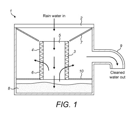
An embodiment of the invention is shown in Figure 1. Figure 1 shows a
storm water drain pit (1) comprising: an inlet for storm water (2); a filter
(3) for
removing particles from the storm water, comprising a cylindrical body (4)
comprising coherent man-made vitreous fibres (MMVF) bonded with a cured
binder composition; wherein the cylindrical body has a hollow centre (5) and
an
outer wall (6).
Figure 1 also shows a guide element (7) for guiding water from the inlet
into the cylindrical body (5); and a sedimentation chamber (8) for
sedimentation
of particles from the storm water. In Figure 1, it can be seen that the
cylindrical
body is positioned below the inlet and above the sedimentation chamber.
Figure 1 also shows an outlet (9) for filtered water; and the outlet is
positioned above the sedimentation chamber and below the inlet. Figure 1
shows a separation element (10) for separating the sedimentation chamber from
the outlet.
Water, such as rain water, can enter via the inlet into the storm water pit
and travels down through the hollow centre of the cylindrical body. The
guiding
element ensures that the water entering the storm water pit is guided into the
cylindrical body. Particles and debris are removed from the water and settle
in
the sedimentation chamber. The water then passes through the walls of the
cylindrical body, and then leaves via the outlet. The separation element and
the
guiding element ensure that the clean, filtered water and rain water do not
mix.
CA 03148942 2022-01-27
WO 2021/028526
PCT/EP2020/072735
The present invention also relates to a filter for a storm water drain. The
invention defines a filter for a storm water drain pit, comprising:
a cylindrical body comprising coherent man-made vitreous fibres (MMVF)
bonded with a cured binder composition; wherein the cylindrical body has a
5 hollow centre and an outer wall;
wherein the cylindrical body has a density in the range of 50 to 200 kg/m3, a
binder content in the range of 2 to 5 wt% and the outer wall has a
circumferential
thickness in the range of 2 cm to 20 cm.
The filter may have any of the preferred features discussed above in
10 detail.
An embodiment of the invention is shown in Figure 2. Figure 2 shows a
filter (3), comprising a cylindrical body (4) which has a hollow centre (5)
and an
outer wall (6).
The present invention also relates to a storm water drain pit liner
15 comprising:
a housing comprising;
an inlet for storm water;
a filter for removing particles from the storm water, comprising a cylindrical
body
comprising coherent man-made vitreous fibres (MMVF) bonded with a cured
binder composition; wherein the cylindrical body has a hollow centre and an
outer wall;
a guide element for guiding water from the inlet into the cylindrical body;
a sedimentation chamber for sedimentation of particles from the storm water,
wherein the cylindrical body is positioned below the inlet and above the
sedimentation chamber;
an outlet for filtered water; wherein the outlet is positioned above the
sedimentation chamber and below the inlet; and
a separation element for separating the sedimentation chamber from the outlet;
wherein the cylindrical body has a density in the range of 50 to 200 kg/m3, a
binder content in the range of 2 to 5 wt% and the outer wall has a
circumferential
thickness in the range of 2 cm to 20 cm.
The storm water drain pit liner may comprise any of the preferred features
discussed above. The benefit of the storm water drain pit liner is that it can
be
installed in the ground in one step to form a storm water drain pit.
CA 03148942 2022-01-27
WO 2021/028526
PCT/EP2020/072735
16
The present invention also relates to use of a filter for removing
particulates from storm water, wherein the filter comprises:
a cylindrical body comprising man-made vitreous fibres (MMVF) bonded with a
cured binder composition; wherein the cylindrical body has a hollow centre and
an outer wall;
wherein the cylindrical body has a density in the range of 50 to 200 kg/m3, a
binder content in the range of 2 to 5 wt% and the outer wall has a
circumferential
thickness in the range of 2 cm to 20 cm.
The filter is as described above. It may have any of the preferred
features described above.
The present invention also relates to a method of emptying a storm water
drain pit. The storm water drain pit comprises:
an inlet for storm water;
a filter for removing particles from the storm water, comprising a cylindrical
body
comprising coherent man-made vitreous fibres (MMVF) bonded with a cured
binder composition; wherein the cylindrical body has a hollow centre and an
outer wall;
a guide element for guiding water from the inlet into the cylindrical body;
a sedimentation chamber for sedimentation of particles from the storm water,
wherein the cylindrical body is positioned below the inlet and above the
sedimentation chamber;
an outlet for filtered water; wherein the outlet is positioned above the
sedimentation chamber and below the inlet; and
a separation element for separating the sedimentation chamber from the outlet;
wherein the cylindrical body has a density in the range of 50 to 200 kg/m3, a
binder content in the range of 2 to 5 wt% and the outer wall has a
circumferential
thickness in the range of 2 cm to 20 cm.
The method of emptying a storm water drain pit comprising the steps:
inserting a storm water drain pit extractor through inlet and the hollow
centre of
the cylindrical body, and into the sedimentation chamber;
using the storm water drain pit extractor to remove any sediment in the
sedimentation chamber; and
removing the storm water drain pit extractor from the sedimentation chamber,
hollow centre of the cylindrical body and the inlet.
CA 03148942 2022-01-27
WO 2021/028526
PCT/EP2020/072735
17
The present invention also relates to a method of installing a filter into a
storm water drain pit, comprising the steps:
(i) inserting a filter into a storm water drain pit; wherein the filter
comprises a cylindrical body comprising coherent man-made vitreous
fibres (MMVF) bonded with a cured binder composition; wherein the
cylindrical body has a hollow centre and an outer wall; wherein the
cylindrical body has a density in the range of 50 to 200 kg/m3, a
binder content in the range of 2 to 5 wt% and the outer wall has a
circumferential thickness in the range of 2 cm to 20 cm.
The filter may have any of the preferred features described above in detail.
The filter for a storm water drain pit according to the present invention
may be made by any known method. Mineral wool may be stone wool, glass
wool, slag wool, etc. and may be manufactured by producing a mineral melt,
spinning fibres from this melt and adding binder to the fibres. The mineral
fibres
with the binder applied thereon are then formed and shaped into mats of
fibres,
a fibrous web or the like. Different production methods exist for making
annular
shaped mineral wool elements, which include cutting, casting or winding of the
annular shape, and which are all well-known methods.
One preferred process by which the filter can be made is by casting. The
process of producing annular mineral fibre elements (such as pipe sections) in
a
casting station is a batch process which involves introducing a non-woven
mineral fibre web including uncured binder into the casting station. The
casting
station is provided with casting tools, which are movable from an open
position
to a closed position. The non-woven mineral fibre web is introduced into the
casting tools, when these are in an open position, and the web is received
between the opposite casting tools, which casting tools are then moved to a
closed position. The mineral fibre web will be formed between the casting
tools
in the casting station, which define the annular configuration of the mineral
wool
element produced in the casting station. Afterwards the casting tools are
heated
for curing the uncured binder to keep the annular shape of the mineral fibre
elements. The casting tools are then separated from one another, and the cast
annular mineral fibre elements are removed from the casting station.
Another preferred method by which the filter may be made is winding. An
annular mineral fibre element (e.g. pipe section or pipe shell) is produced
from a
CA 03148942 2022-01-27
WO 2021/028526
PCT/EP2020/072735
18
thin mat of mineral wool impregnated with a liquid uncured binder. The annular
mineral wool element is produced by winding the thin mat of mineral wool onto
a
rotatable mandrel. The winding includes a plurality of turns onto the mandrel.
An
endless belt is provided for driving the mandrel and is mounted to engage with
the mandrel over a periphery thereof. The thin mat is fed between the endless
belt and the mandrel and wound up on the latter one. Preferably, a plurality
of
pressure rollers is provided to execute pressure on the belt in the direction
of the
mandrel, and this is geared resiliently so that it can move away under
influence
of the pressure rollers, as the sleeve grows in diameter or thickness. The
thin
mat of mineral wool is wound around or onto a mandrel until it has obtained a
suitable thickness.
The annular mineral fibre element may be cured on the mandrel or in a
curing oven, where the binder is cured to keep the desired form. The annular
mineral fibre element can thereafter be cut into the desired size after the
mandrel has been removed from same.
Another preferred method by which the filter may be made is cutting.
Annular mineral fibre elements can also be produced by making an annular
cutting of the mineral fibre element from a larger mineral wool batt. Such a
method is described in WO 98/12466.
The most preferred method for making the filter according to the present
invention is by winding.
Examples
Embodiments according to the present invention were prepared and
water permeability was tested. The results are shown in the graph of Figure 3.
A cylindrical filter comprising man-made vitreous fibres cured with a
binder composition was prepared. The filter had a density of 120 kg/m3 and a
binder content of 3.5 wt%. The filter had a hollow centre and the following
dimensions:
- inner diameter 14 cm
- outer diameter 19 cm
- height 30 cm
- surface area 1260 cm2
CA 03148942 2022-01-27
WO 2021/028526
PCT/EP2020/072735
19
For the water permeability test, a hose was inserted into the hollow centre of
the
filter. The water flow from the hose was such that a maximum pressure
difference was achieved. The resulting flow rates are shown in Figure 3. For
both Test 1 and Test 2, the flow rate was around 60 litres/minutes.