Note: Descriptions are shown in the official language in which they were submitted.
WO 2021/062239
PCT/US2020/052843
TANKLESS WATER HEATER HAVING INTEGRATED SCALE CONTROL MODULE
CROSS REFERENCE TO RELATED APPLICATIONS
[0001] This application claims priority to U.S. Provisional
Patent Application No.
62/907,280 filed on September 27, 2019, the contents of which are incorporated
by reference
herein.
BACKGROUND
[0002] The present invention relates to a tankless water
heater having an integrated scale
control module.
[0003] Traditional tankless water heaters have a water
hookup for cold water in and hot
water out, a fuel hookup for the supply of natural gas or propane (for gas-
fired tankless water
heaters), a vent hookup for the venting of products of combustion, and
possibly an electrical
hook up to power the water heater's controller and electrical components such
as a water pump
and a blower. If the installation of a traditional tankless water heater calls
for a scale control
solution due to the characteristics of water being supplied to the water
heater, that solution is
plumbed into the water supply line upstream of the water heater. A scale
control solution is
called for when the supply water includes minerals and other impurities that
can lead to scale
buildup in the heat exchanger of the tankless water heater.
SUM:MARY
[0004] In one embodiment, the invention provides a tankless
water heater comprising: a
source of heat; a scale control module for treating supply water to generate
treated water with
reduced scale-forming characteristics, the scale control module including a
SCM inlet adapted to
receive the supply water and a SCM outlet for delivering the treated water
from the scale control
module; a heat exchanger having a water inlet in fluid communication with the
scale control
module to receive the treated water, the heat exchanger adapted to transfer
heat from the source
of heat to the treated water as the treated water flows through the heat
exchanger to generate
heated treated water, the heat exchanger including a water outlet for delivery
of the heated
treated water, and a cabinet defining an interior space which encloses the
heat exchanger and
source of heat; wherein the SCM inlet and the SCM outlet are within the
interior space.
1
CA 03149272 2022-2-23
WO 2021/062239
PCT/US2020/052843
100051 In some embodiments, the cabinet includes a wall to
which the scale control module
is rigidly mounted. In some embodiments, the scale control module includes a
SCM cartridge in
which the supply water is treated, the SCM cartridge being external to the
cabinet. In some
embodiments, the scale control module further includes a SCM connector
including the SCM
inlet and SCM outlet and a SCM cartridge that is removably mounted to the SCM
connector. In
some embodiments, the source of heat includes a gas burner generating products
of combustion
and the heat exchanger includes a plurality of finned tubes through which the
treated water flows
and over which the products of combustion flow.
100061 In another embodiment, the invention provides a
tankless water heater including a
source of heat, and a scale control module for treating supply water to
generate treated water
with reduced scale-forming characteristics compared to the supply water. The
scale control
module includes a SCM inlet adapted to receive the supply water and a SCM
outlet for
delivering the treated water from the scale control module. A heat exchanger
has a water inlet in
fluid communication with the SCM outlet to receive the treated water. The heat
exchanger is
adapted to transfer heat from the source of heat to the treated water as the
treated water flows
through the heat exchanger to generate heated treated water. The heat
exchanger includes a
water outlet for delivery of the heated treated water. A cabinet defines an
interior space which
encloses at least a portion of the heat exchanger. The SCM inlet and the SCM
outlet are within
the interior space.
100071 In yet another embodiment, the invention provides a
tankless water heater including a
source of heat, and a scale control module for treating supply water to
generate treated water
with reduce scale-forming characteristics. The scale control module includes a
SCM connector
having a SCM inlet adapted to receive the supply water and a SCM outlet for
delivering the
treated water from the scale control module, and a SCM cartridge that is
removably mounted to
the SCM connector. The supply water is treated by the SCM cartridge to become
treated water.
A heat exchanger has a water inlet in fluid communication with the SCM outlet
to receive the
treated water. The heat exchanger is adapted to transfer heat from the source
of heat to the
treated water as the treated water flows through the heat exchanger to
generate heated treated
water. The heat exchanger includes a water outlet for delivery of the heated
treated water A
cabinet defines an interior space which encloses at least a portion of the
heat exchanger. The
2
CA 03149272 2022-2-23
WO 2021/062239
PCT/US2020/052843
SCM connector is secured to a wall of the cabinet such that the SCM inlet and
the SCM outlet
are within the interior space and the SCM cartridge is external to the
cabinet.
[0008] In yet still another embodiment, the invention
provides a method of generating heated
treated water. The method includes (a) providing a tankless water heater
including a cabinet
defining an interior space. A water supply inlet extends through the cabinet
into the interior
space. A hot water outlet extends through the cabinet out of the interior
space. A source of heat
is at least partially within the interior space. A heat exchanger is at least
partially enclosed in the
interior space. A scale control module has a SCM inlet and a SCM outlet. At
least the SCM
inlet and the SCM outlet are enclosed in the interior space. The method
further includes (b)
generating heat with the source of heat, (c) providing supply water to the
tankless water heater
through the water supply inlet, and (d) conducting the supply water from the
water supply inlet
into the scale control module through the SCM inlet. The method further
includes (e) treating
the supply water in the scale control module to generate treated water with
reduced scale-
forming characteristics compared to the supply water, and (f) conducting the
treated water from
the scale control module through the SCM outlet to the heat exchanger. The
method further
includes (g) transferring the heat generated by the source of heat to the
treated water as the
treated water flows through the heat exchanger to generate the heated treated
water, and (h)
delivering the heated treated water out of the cabinet through the hot water
outlet
[0009] Other aspects of the invention will become apparent
by consideration of the detailed
description and accompanying drawings.
BRIEF DESCRIPTION OF THE DRAWINGS
[0010] Fig. 1 is a perspective view of a water heater
constructed according to the present
invention.
[0011] Fig. 2 is a bottom perspective view of the water
heater.
[0012] Fig. 3 is a front perspective view of the water
heater with the cabinet removed.
[0013] Fig. 4 is a rear perspective view of the water
heater with the cabinet removed.
[0014] Fig. 5 is a side perspective view of the water
heater with the cabinet removed.
3
CA 03149272 2022-2-23
WO 2021/062239
PCT/US2020/052843
100151 Fig. 6 is a perspective view of a scale control
module of the water heater with a
cartridge removed.
[0016] Fig 7 is a perspective view of the scale control
module with the cartridge installed.
100171 Fig 8 is a perspective view of an alternative
embodiment of the invention.
[0018] Fig. 9 is a perspective view of another alternative
embodiment.
DETAILED DESCRIPTION
[0019] Before any embodiments of the invention are
explained in detail, it is to be
understood that the invention is not limited in its application to the details
of construction and the
arrangement of components set forth in the following description or
illustrated in the following
drawings. The invention is capable of other embodiments and of being practiced
or of being
carried out in various ways.
[0020] The present invention addresses problems and costs
that can arise from installing a
separate scale control solution upstream of a tankless water heater. Such
problems include, for
example, the difficulty and cost of installing such a scale control solution.
Such problems and
costs have led to limited adoption of scale control solutions in the market
despite the fact that
heat exchanger failure in tankless water heaters is most commonly associated
with scale buildup
in the heat exchanger.
[0021] The present invention addresses the problem of scale
buildup in the heat exchanger
by integrating a scale control module (SCM) into a tankless water heater. As
used herein, the
term SCM includes a cartridge containing a media that renders scale-inducing
impurities (e.g.,
calcium and magnesium) in water inert or non-reactive in the sense that the
scale-inducing
impurities are in a state that will not bind to the heat exchanger and form
scale on the heat
exchanger. Water that has flown through the SCM cartridge has reduce scale-
forming
characteristics as a consequence of its interaction with the media. The water
flowing out of the
SCM cartridge (with reduced scale-forming characteristics) is referred to
herein as treated water.
The term "reduced" when describing the scale-forming characteristics of the
treated water is in
reference to the supply water provided to the water heater
4
CA 03149272 2022-2-23
WO 2021/062239
PCT/US2020/052843
00221 As used herein, the terms "integration,"
"integrate," "integrated," and other variations
mean that the SCM is not an optional component or add-on for the water heater.
A tankless water
heater with integrated SCM is a plug-and-play system for the installer. The
water supply and hot
water delivery conduits can be hooked up to the tankless water heater and it
is ready to go with
the scale control functionality. No additional plumbing to a separate scale
control solution is
required when installing a tankless water heater having an integrated SCM
according to the
present invention. A tankless water heater having an integrated SCM according
to the present
invention is simpler to install than a traditional water heater with a
separate SCM in the water
supply line. A simpler installation will typically take less time and lower
cost compared to a
more complex installation. As such, the present invention has the potential to
reduce installation
time and cost compared to traditional tankless water heaters that required a
separate upstream
SCM.
100231 A tankless water heater having an integrated SCM
according to the present invention
may include a recirculation line. Indeed, the embodiment of the invention
described below and
illustrated in the accompanying drawings includes a recirculation line. It is
noted that the water
supply to the illustrated tankless water heater could be directly connected to
the recirculation
return so that supply water would bypass the SCM. Nonetheless, the illustrated
tankless water
heater is still considered a tankless water heater having an integrated SCM
because the SCM is a
permanent part of the tanldess water heater and supply water must flow through
the SCM prior to
reaching the heat exchangers in the ordinary intended configuration of the
tankless water heater
that uses the SCM,
100241 A tankless water heater having an integrated SCM
according to the present invention
may include a permanent SCM cartridge or a SCM cartridge that can be removed
and replaced.
Both would be considered an "integrated" SCM as the term is used herein, and
the term
"integrated" should not be construed as limited to a permanent SCM cartridge.
100251 A characteristic of the invention, as will be
explained below, is a continuous water
pathway that supplies all components of a tankless water heater. To the
knowledge of the
inventors, there is no tankless water heater currently available that includes
a continuous
pathway housed inside the cabinet of the tankless water heater. This provides
the plug-and-play
CA 03149272 2022-2-23
WO 2021/062239
PCT/US2020/052843
aspect of the invention mentioned above. In each embodiment or configuration
of the present
invention, the water supply hookup for the tankless water heater communicates
with a water
conduit internal to the cabinet The water flows through the internal
components and out the hot
water outlet of the tankless water heater without external plumbing. As
mentioned above and
discussed in more detail below, the integrated SCM cartridge may be configured
as an internal or
external component, but in both instances the SCM connections (i.e., the inlet
and outlet to the
SCM) are internal to the cabinet. To the inventors' knowledge there is no
tankless water heater
currently configured this way. Consequently, the addition of a scale control
solution to known
tankless water heaters requires a water pathway connections exterior to the
cabinet which would
require a relatively more complex installation process.
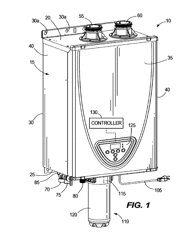
[0026] Referring to Figs. 1-2, the present invention
provides a tankless water heater 10
including a case or cabinet 15. The cabinet 15 includes a top wall 20, a
bottom wall 25, a back
wall 30, a front wall 35, and side walls 40 as illustrated. An interior space
50 (Fig. 3) is defined
between the walls 20, 25, 30, 35, 40 of the cabinet 15. As illustrated in Fig.
1, an air intake 55
and an exhaust 60 are mounted to and penetrate through the top wall 20. As
illustrated in Fig. 2,
a water supply inlet 65, hot water outlet 70 (including a pressure relief
valve 75), recirculation
return 80, bypass drain 85, condensate drain 90, gas hookup 100, and electric
power cord 105
penetrate through or are mounted to the bottom wall 25.
[0027] As will be described in more detail below, the
tankless water heater 10 also includes a
scale control module (SCM) 110 which in the embodiment illustrated in Figs. 1-
7 includes a
SCM connector or manifold 115 and a SCM cartridge 120 received in the SCM
connector 115.
The SCM connector 115 is mounted to the bottom wall 25 and (referring to Figs.
3-7) includes a
SCM inlet 115a for receiving supply water to the SCM cartridge 120 and a SCM
outlet 115b for
delivering treated water from the SCM cartridge 120. The SCM inlet 115a and
SCM outlet 115b
are referred to collectively as the SCM connections and are internal to the
cabinet 15, within the
interior space 50.
[0028] The cartridge 120 may be a multi-stage design,
containing one main filter and one (or
more) pre-filter(s) together in a single housing or in multiple housings
connected in tandem. The
filter or filters can contain a bypass that circumvents one or more of the pre-
filter stages in the
6
CA 03149272 2022-2-23
WO 2021/062239
PCT/US2020/052843
case of abnormally high contamination creating an unacceptable pressure drop.
The purpose of
the main filter will be to provide scale reduction treatment for a tanldess
water heater. The
purpose of the pre-filter(s) is to improve or protect the scale reduction
capability of the main
filter. The term "filter" is used herein to include physical filters and also
media that reacts with
scale-inducing impurities (e.g., calcium and magnesium) in the water to render
the scale-
inducing impurities inert.
100291 During installation, the air intake 55 may be
connected to an air supply conduit or
may simply be exposed to the air around the tankless water heater 10. The
exhaust 60 is
connected to an exhaust system of the room or building in which the tankless
water heater 10 is
installed. The water supply inlet 65 is connected to a water supply for the
building for the receipt
of supply water (i.e., untreated water) to the water heater 10 and the hot
water outlet 70 is
connected to the hot water delivery system of the building for the delivery of
heated treated
water to an end user. The recirculation return 80 is connected to a remote
point in the hot water
delivery system (e.g., near a remote hot water faucet). The bypass drain 85
and condensate drain
90 can be plumbed to a water disposal (e.g. sewer) system of the building. The
gas hookup 100 is
connected to a supply of combustible gas (e.g., natural gas). The power cord
105 is plugged into
an electrical outlet. Each of the water supply inlet 65, hot water outlet 70,
recirculation return 80,
bypass drain 85, condensate drain 90, gas hookup 100, and power cord 105 can
be characterized
as extending through the bottom wall 25 of the cabinet into or out of the
interior space 50.
100301 With continued reference to Figs. 1 and 2, the back
wall 30 includes mounting
structure 30a for hanging the tankless water heater 10 on a support structure.
A user interface
125 is mounted in the front wall 35. The front wall 35 in the illustrated
embodiment is removable
from the side walls 40, top wall 20, and bottom wall 25 for access to and
servicing of the
components of the tankless water heater 10 in the interior space 50 (the
"internal components").
[0031] The internal components include, among other
components discussed below, a
controller 130 (Figs. 1-3) which is either integrated with the user interface
125 or separately
mounted in the interior space 50 (e.g., in the location and housing noted in
Fig. 3), an air intake
pan 135, a power burner 140 (including a blower 145, a gas valve 150, and
combustor 155), a
primary heat exchanger 160, a secondary heat exchanger 165, a condensate pan
170, and a flue
7
CA 03149272 2022-2-23
WO 2021/062239
PCT/US2020/052843
175. It should be noted that the illustrated power burner 140 is only one
example of a source of
heat suitable for use with the present invention. The source of heat could
alternatively be an
electric heating element, a condenser coil of a refrigeration cycle (e.g., a
heat pump), hydronic
heat from a boiler, solar power, or any other suitable source of heat for the
given application. As
illustrated, all the internal components are fully enclosed within the
interior space 50. In other
embodiments one or more of the internal components (e.g., a portion of the
power burner 140 or
heat exchanger 160, 165) may extend out of the interior space 50 if required
for a particular
purpose, in which case such internal components would be at least partially
enclosed within the
interior space 50.
100321 The water plumbing includes a first conduit 180
communicating between the water
supply inlet 65 and the SCM inlet 115a of the SCM connector 115, a tee 185
communicating
with the SCM outlet 115b of the SCM connector 115, a second conduit 190
communicating
between the tee 185 and a water inlet of the secondary heat exchanger 165, a
third conduit 195
communicating between a water outlet of the secondary heat exchanger 165 and a
water inlet of
the primary heat exchanger 160, and a fourth conduit 200 communicating between
a water outlet
of the primary heat exchanger 160 and the hot water outlet 70 through the
bottom wall 25 of the
cabinet 15. The water plumbing also includes a water pump 205 and a
recirculation conduit 210
communicating between the recirculation return 80 and the tee 185 Other
internal components
include a small drain conduit 215 communicating between the second conduit 190
and the
bypass drain 85, a condensate conduit 220 communicating between the condensate
pan 170 and
the condensate drain 90, and a gas supply conduit 225 communicating between
the gas valve 150
and the combustor 155 of the power burner 140. The internal components also
include various
electrical connectors, wires, and sensors that communicate between the
controller 130 and the
other internal components to enable the controller 130 to operate the tankless
water heater 10.
The controller 130 and combustor 155 are shown schematically and are not
necessarily in the
exact positions shown in the drawings.
100331 When there is a call for hot water (e.g., when the
controller 130 senses or determines
that there is flow of water through the tanldess water heater 10 and performs
all system checks
necessary to start operation), the controller 130 energizes the power burner
140_ When energized,
the blower 145 draws air into the power burner 140 through the air intake 55.
At the same time,
8
CA 03149272 2022-2-23
WO 2021/062239
PCT/US2020/052843
the gas valve 150 is opened to permit the combustible gas to flow to the
burner. The air provided
by the blower 145 and the combustible gas provided by the gas valve 150 are
mixed and then
ignited at the combustor 155 to generate hot products of combustion. The
products of
combustion are forced under the influence of the blower 145 through the
primary heat exchanger
160, secondary heat exchanger 165, condensate pan 170, flue 175, and out the
exhaust 60. At the
same time, supply water flows into the water heater 10 through the water inlet
65, through the
first conduit 180, SCM cartridge 120 (where scale-inducing impurities are
rendered non-binding
and the water becomes treated water), second conduit 190, secondary heat
exchanger 165, third
conduit 195, primary heat exchanger 160, fourth conduit 200 and out the hot
water outlet 70 to
the hot water delivery system of the building and ultimately to an end user.
The hot water
flowing out of the primary heat exchanger 160 and secondary heat exchanger 165
can be referred
to as heated treated water. It should be noted that the heat exchanger of the
present invention is
not limited to the specific primary heat exchanger 160 and secondary heat
exchanger 165
illustrated and that the term heat exchanger is used to refer to either of
those, the two in
combination, and other types of heat exchangers that meet the basic
functionality of transferring
heat from the source of heat to the treated water to generate heated treated
water.
[0034] The primary heat exchanger 160 includes finned tubes
through which the treated
water flows and over which the products of combustion flow to heat the water.
The secondary
heat exchanger 165 includes smooth tubes through which the colder water
initially flows (prior
to entering the primary heat exchanger 160) and over which the cooler products
of combustion
(having lost heat in the primary heat exchanger 160 prior to the primary heat
exchanger 160)
flow. The products of combustion condense in the secondary heat exchanger 165
and the
condensate is collected in the condensate pan 170. The condensate drains from
the condensate
pan 170 through the condensate conduit 220 and out the condensate drain 90.
[0035] During standby (when there is no call for hot
water), the water in the hot water
delivery system of the building may drop below a desired temperature. In such
an event, the
controller 130 may energize the power burner 140 as described above and also
energize the
recirculation pump to move water from the recirculation return 80 through the
recirculation
conduit 210 to the second conduit 190 (thereby bypassing the SCM cartridge
120). The pump
moves the water in a closed loop through the tankless water heater 10 and the
hot water delivery
9
CA 03149272 2022-2-23
WO 2021/062239
PCT/US2020/052843
system until the controller 130 determines that the hot water delivery system
is loaded up with
hot water again.
100361 The illustrated SCM 110 includes the SCM connector
115 and SCM cartridge 120.
The SCM connector 115 is rigidly fastened to or formed integrally with the
bottom wall 25 of the
cabinet 15 with the SCM connectors (SCM inlet 115a, SCM outlet 115b) extending
into the
interior space 50. In the embodiment illustrated in Figs. 1-7, and with
particular reference to
Figs. 6 and 7, the SCM connector 115 includes a mounting flange 230 with holes
235 through
which fasteners are extended to mount the flange 230 against the bottom wall
25. The SCM
connector 115 is rigidly mounted to the bottom wall 25. The term rigidly
mounted to includes the
illustrated arrangement and any other suitable way to create this rigid
connection for the purpose
described in the next paragraph. In particular, the SCM connector 115 is
coupled to the cabinet
15 such that the SCM inlet 115a and the SCM outlet 115b extend outwardly from
a first side of
the flange 230 into the interior space 50, and the SCM cartridge 120 is
removably mounted to a
second side of the flange 230 opposite the first side.
100371 The SCM cartridge 120 is detachably connected to the
SCM connector 115 with
ramped surfaces 240 (which also includes threads in other embodiments), such
that the SCM
cartridge 120 is connected to the SCM connector 115 by inserting the SCM
cartridge 120 and
giving the cartridge 120 a quarter or half turn in a tightening direction. The
SCM connector 115
may include a valve that is unseated only when the SCM cartridge 120 is
connected to avoid
drainage of water when changing cartridges. The rigid mounting of the SCM
connector 115 to
the bottom wall 25 fixes the SCM connector 115 so that the SCM cartridge 120
can be turned or
otherwise moved with respect to it into a connected condition, without having
to separately hold
the SCM connector 115 (e.g., with another hand, pair of hands or a tool). The
rigid mounting of
the SCM connector 115 thereby facilitates rotation of the SCM cartridge 120
with respect to the
SCM connector 115 during installation and removal of the SCM cartridge 120.
100381 The illustrated SCM connector 115 and SCM cartridge
120 are external components
(i.e., outside of the interior space 50 of the cabinet 15) of the tankless
water heater 10, except that
the SCM connections (SCM inlet 115a, SCM outlet 115b) are internal to the
cabinet 15. One
advantage of an external SCM 110 is that the SCM cartridge 120 can be accessed
for service
CA 03149272 2022-2-23
WO 2021/062239
PCT/US2020/052843
without having to open the cabinet 15. Another possible advantage is that any
leak of water in
the tankless water heater 10 can quickly be assessed as coming from the
internal components or
the external SCM, so that the leak can be more quickly repaired.
100391 Fig. 8 illustrates another embodiment of the water
heater 10' in which the SCM
cartridge 120 is permanently mounted to the bottom wall 25 of the cabinet 15,
without an
intervening SCM connector. The SCM cartridge 120 must still include SCM
connections (i.e., a
SCM inlet and SCM outlet) to which the respective first water conduit 180 and
tee 185 are
plumbed. The plumbing may be by a threaded connection or by a permanent
connection such
that the cartridge 120 could only be removed from the water circuit by
breaking the cartridge 120
or water conduits 180, 190. The components of the water heater 10' are
essentially the same or
equivalent to those described above, so the same reference numbers are used in
Fig. 8 and not all
reference numbers are provided. In this embodiment, the SCM cartridge 120
includes the flange
230 (i.e., the flange 230 having mounting holes 235 is integrally formed with
or directly mounted
to the SCM cartridge 120). In this embodiment, the SCM cartridge 120 is not
replaceable
because the SCM cartridge 120 has an expected useful life that is at least as
long as the expected
useful life of the overall tankless water heater 10'. In this embodiment of
the water heater 10',
the permanent SCM cartridge 120 is an external component although the SCM
connections
extend into the internal space 50.
[0040] Fig. 9 illustrates another embodiment of the water
heater 10" in which the SCM
cartridge 120 is permanently mounted within the interior space 50 of the
cabinet 15. The
components of the water heater 10" are essentially the same or equivalent to
those described
above, so the same reference numbers are used in Fig. 9 and not all reference
numbers are
provided. The SCM connector 115 may be simplified or essentially eliminated in
a permanent
SCM because there is no need for a valve or threads in the SCM connector 115
since the SCM
cartridge 120 will never be changed. As with other embodiments of the
invention, the SCM
cartridge 120 includes SCM connections in the form of a SCM inlet and SCM
outlet that
respectively receive and deliver water to and from the cartridge 120. The SCM
connections are
in the interior space 50 of the cabinet 15. In this embodiment, the SCM
cartridge 120 is an
internal component and is fully enclosed within the interior space 50
described above.
11
CA 03149272 2022-2-23
WO 2021/062239
PCT/US2020/052843
100411 Thus, the invention is to cover all modifications,
equivalents, and alternatives falling
within the spirit and scope of the invention as defined by the following
claims.
12
CA 03149272 2022-2-23