Note: Descriptions are shown in the official language in which they were submitted.
I
Use of a composite material for absorbing and distributing liquids in
actively and/or passively cooled current-carrying systems
The present disclosure relates to the use of a composite material for
absorbing
and distributing liquids in actively and/or passively cooled current-carrying
systems, more particularly in actively and/or passively cooled current-storage
systems. The present disclosure relates further to an absorber pad and to an
actively and/or passively cooled current-carrying system, each comprising the
composite material.
Current-carrying systems, more particularly battery systems, are gaining
increasingly in importance, as they are needed for the drive of electric and
hybrid vehicles. A "current-carrying system", as is known, is a system through
which electrical current flows. Current-carrying systems of practical
relevance
are "current-storage systems", these being systems for the storage of energy
which is available instantaneously but not required, for the purpose of later
utilization. This storage frequently entails a conversion of the energy form -
for
example, from electrical into chemical energy. As and when required, the
energy is then converted back into the desired electrical form. Battery
systems,
as is known, are modules which are connected in series or in parallel and
comprise secondary or primary cells connected in series or in parallel.
Further
current-storing systems are accumulators, these being modules connected in
series or in parallel and comprising secondary cells connected in series or in
parallel. Likewise current-storing systems of practical relevance are
capacitors,
these being passive electrical components having the ability to store
electrical
charge in a direct-current circuit, and the associated energy, statically in
an
electrical field.
In order to ensure optimal functioning of the systems, it is necessary to keep
the
temperature of the battery cells within a desired temperature range. In order
to
Date Recue/Date Received 2023-05-10
2
prevent the temperature exceeding and/or falling below the operating
temperature, active or passive conditioning systems are employed. Having
been found particularly appropriate is the use of liquid conditioning medium
having a high heat capacity, which, with good thermal conduction, is guided
along the battery cells in a heat exchanger.
In general, furthermore, the systems are not hermetically sealed off from
their
surroundings. This means that they allow gas exchange with the surroundings.
In order to prevent contaminant penetration, the incoming air is filtered.
Microporous foils or nonwovens, for example, are used for this purpose.
All of these approaches do allow particles to be filtered, but not gases, and
in
particular not water vapor either. Water vapor may therefore enter through the
foils into the electronic housing. Because the interior of the housing is
cooled,
however, it is possible for water to condense on cold points in the housing
(when its dew point is exceeded). Given that current-carrying parts in
particular
are cooled, condensation occurs at the locations where it is most critical.
If, furthermore, the temperature within the housing itself is always situated
at a
low level, it is difficult to remove the condensate formed from the housing
again.
Conceivable options here would include, for example, pumps, control valves, or
baking. These approaches are costly and inconvenient, and may be susceptible
to faults. Baking, furthermore, is out of the question for many applications
(e.g.,
battery systems).
A tried and tested means for absorbing water are desiccants, which are
installed in or upstream of the housing and which bind water irreversibly. A
disadvantage in this case, however, is that such desiccants absorb not only
liquid water, but also water vapor. If the desiccants are sited in a housing,
they
also dehumidify the gas space in the housing. As a consequence of this,
therefore, the housing also draws in water vapor which under normal
circumstances simply would not have entered the housing. Drying cartridges of
Date Recue/Date Received 2023-05-10
3
this kind, accordingly, act not only as moisture absorbers but also as
moisture
wicks.
A further problem is that in the event, for example, of an accident befalling
a
vehicle equipped in this way, there may be leakages and, consequently, an
emergence of the conditioning medium from the cooling element. The
conditioning medium may then come into direct contact with the battery cells
and because of its conductivity may trigger a short circuit, for example.
A customary desiccant is P205. While this desiccant has an extremely high
absorption capacity for water, it forms liquid phosphoric acid on absorption
of
water. This acid may lead to corrosion and, because of its electrical
conductivity, poses a risk for electrical applications. In addition, the water
absorption is irreversible. Other typical desiccants such as CaCl2 react
similarly.
For this reason, the aforesaid desiccants are technically unrewarding. The
desiccants are typically welded loose into bags (dessicant bags) and are
consequently not reliably secured.
Other known liquid-absorbing and more particularly water-absorbing substances
are superabsorbents, for example. Advantageous features of superabsorbents
are that they have a very high water absorption capacity, give a neutral
chemical reaction (including with respect to organic solvents), and can also
be
reversibly loaded.
With polar liquid media, superabsorbents result in significant swelling, and
possibly to formation of a gel. The swelling in particular may cause liquid
transport channels to become blocked by the process of swelling (referred to
as
blocking effect), with no further possibility for subsequent absorption. In
electronic devices, furthermore, swelling is disadvantageous or harmful in
light
of two further considerations: firstly, the swollen material may build up
mechanical pressures, which may cause electrical contacts to be parted, for
Date Recue/Date Received 2023-05-10
4
example. Secondly, in the event of uncontrolled swelling, the swollen material
may cause electrical short circuits if it comes into contact with current-
carrying
parts.
Where the superabsorbents are present in the loose form, there is on the one
hand a problem of potential dusting in the dry state, and on the other hand
their
removal in the swollen state is not simple, since swollen superabsorbent
particles lack mechanical stability. This leads to problems in repair and/or
in the
event of maintenance.
Superabsorbent materials are known from medical products, for example, and
are described in DE102006031418A1, for example.
EP2731164 (Al) describes a battery system comprising battery cells, at least
one absorption element, and a conditioning system featuring a liquid
conditioning medium for the cooling and/or heating of the battery cells in a
battery housing. The absorption element for absorbing the liquid conditioning
medium is disposed between the battery cells and the battery housing, the
absorption element being a nonwoven, which nonwoven has an average mass
per unit area of 250 to 700 g/m2 and comprises fibers of at least two
different
types, with at least one of the fiber types being a support fiber and at least
one
other of the fiber types being an absorptive fiber.
A disadvantage of using absorptive fibers is that their absorption capacity is
generally lower than that of comparative absorbent particles. Furthermore,
they
generally possess a lower thermal stability both in the dry and in the swollen
states. The use of absorbing fibers can lead to a gel blocking effect,
furthermore, as elucidated above.
The above information is presented as background information only to assist
with an understanding of the present disclosure. No assertion or admission is
made as to whether any of the above, or anything else in the present
Date Recue/Date Received 2023-05-10
5
disclosure, unless explicitly stated, might be applicable as prior art with
regard
to the present disclosure.
At least some aspects and embodiments according to the present disclosure
provide solutions, including to deficiencies in existing approaches. In an
aspect,
the present disclosure provides a material which has good water absorption and
retention. The material may also be capable of reversible binding of water and
possibly water vapor. Furthermore, the material may exhibit controlled
swellability and may enable prevention of a blocking effect. In addition, the
material may be a low-dust material in use.
In an aspect according to the present disclosure, a composite material is
provided, where the composite material comprises a backing layer and a liquid-
absorbing layer fixed on the backing layer, where the liquid-absorbing layer
comprises fixed superabsorbent particles, where, on the side of the liquid-
absorbing layer facing away from the backing layer, there is a liquid-
distributing
layer which is in liquid-conducting contact with the liquid-absorbing layer
and
which absorbs and distributes a liquid for absorption in the plane of the
composite material, for absorbing and distributing liquids in actively and/or
passively cooled current-carrying systems, more particularly in actively
and/or
passively cooled current-storage systems.
In accordance with the present disclosure it has been found that the composite
material described above is outstandingly suitable for absorbing and
distributing
liquids in actively and/or passively cooled current-carrying systems, since
the
fixing of the superabsorbent particles significantly lowers the risk of
dusting. The
superabsorbent particles may be fixed on the backing layer, by means of a
binder, for example. This is an advantage particularly under mechanical
loading,
of the kind occurring, for example, when the composite material is used in an
automobile. Furthermore, the fixing enables the use of superabsorbents in
particle form. These have the advantage over superabsorbent fibers of having a
higher absorption capacity, for comparable thermal stability, in both the
dried
Date Recue/Date Received 2023-05-10
6
and the swollen states. Furthermore, it has surprisingly been found that fixed
superabsorbent particles permit more rapid absorption of water vapor,
combined with more complete release of water vapor, than loose
superabsorbent particles do. The composite material, moreover, exhibits a very
low gel blocking effect, since the liquid-distributing layer that is used
absorbs
and distributes the liquid for absorption in the plane of the composite
material.
This enables optimum utilization of the absorption capacity of the liquid-
absorbing layer.
In accordance with the present disclosure the composite material is suitable
for
a wide variety of different actively and/or passively cooled current-carrying
systems, examples being battery systems, inverter/power electronics systems
and/or charging stations. The liquids absorbed may be any of a very wide
variety, examples being water and/or other cooling media, such as water-glycol
mixtures, for example.
In at least some embodiments, current-carrying systems according to the
present disclosure may be current-carrying systems, and may include, for
example, a current-storage system, a current-carrying energy converter, a
transformer, a power electronics system, a control electronics system, a
processor-controlled system, a charging station, an inverter, a rectifier, an
electrolyzer and/or combinations thereof.
In at least some embodiments, current-storage systems according to the
present disclosure may be battery systems, capacitors and/or accumulators.
Superabsorbents are distinguished by the ability to absorb and bind liquid
outstandingly. According to the present disclosure, a superabsorbent is
understood to be a polymer which is capable of drawing up/absorbing a multiple
- up to 500 times - its own weight of liquids, for example water, the polymer
increasing in volume in this process.
Date Recue/Date Received 2023-05-10
7
Superabsorbents in the swollen state form hydrogels. Suitable superabsorbents
are, in particular, crosslinked polymers which are polar. Examples include
polyacrylamide, polyvinylpyrrolidone, amylopectin, gelatin and cellulose.
Other
examples are copolymers of acrylic acid (propenoic acid, H2C=CH-COOH)
and/or sodium acrylate (sodium salt of acrylic acid, H2C=CH-COONa) on the
one hand and acrylamide on the other. In that case the ratio of the two
monomers to one another may vary.
The aforementioned monomers are generally admixed with what is called a
.. core crosslinker (CXL), which joins (crosslinks) the resultant long-chain
polymer
molecules to one another at certain locations by chemical bridges. As a result
of
these bridges, the polymer becomes water-insoluble. What is called a surface
crosslinker (SXL) may additionally be used. In that case a further chemical is
applied to the surface of the particles, and forms a second network, by
heating,
only on the outer layer of the particle. This shell supports the swollen gel
in
maintaining its integrity even when subject to external loading (movement,
pressure).
In at least one embodiment, the superabsorbent particles are fixed on the
backing layer with a binder, more particularly with a water-soluble binder,
such
as, for example, polyvinyl alcohol, starch, polyvinylpyrrolidone, casein glue,
polyvinylbutyral, and/or with a water-swellable binder, such as, for example,
at
least partly crosslinked polyvinyl alcohol and/or partly crosslinked starch. A
water-soluble binder refers to binders having a water solubility of at least 1
g/I,
for example 1 WI to 400 g/I, or from 2 g/I to 350 g/I, or from 5 g/I to 300
gil,
measured in each case at 23 C. An advantage of using water-soluble binders
and/or water-swellable binders is that there are no limitations on the free
swellability of the superabsorbent.
.. The fraction of the water-soluble binder and/or water-swellable binder,
based on
the total amount of binder, may be at least 70 wt%, for example 70 wt% to
100 wt%, or from 80 wt% to 100 wt%, or from 90 wt% to 100 wt%.
Date Recue/Date Received 2023-05-10
8
In an embodiment, the superabsorbent particles comprise a swelling retardant.
An advantage of this is that the swelling of the superabsorbent particles can
be
retarded, thereby optimizing the distribution of the liquid for absorption and
enabling particularly effective utilization of the absorbing area of the
liquid-
absorbing layer. The swelling retardant may consist of the same materials as
the water-soluble and/or swellable binder. The superabsorbent particles may be
enveloped at least partially, or completely, by the swelling retardant.
The liquid-distributing layer absorbs a liquid for absorption and distributes
it in
the plane of the composite material.
In an embodiment, the liquid-distributing layer comprises a nonwoven fabric, a
woven fabric, a knitted fabric, an open-pore foam, a binder, a water-soluble
and/or water-swellable binder. Example water-soluble binders are polyvinyl
alcohol, starch, polyvinylpyrrolidone, casein glue, polyvinylbutyral. Example
water-swellable binders are, for example, at least partly crosslinked
polyvinyl
alcohol and/or partly crosslinked starch. Advantages of these materials are
their
effective water permeability coupled with a high structural integrity even in
the
wet state. Example nonwovens are spunbonded nonwovens, wet-laid
nonwovens and/or dry-laid nonwovens. The basis weight may be 10 g/m2 to
500 g/m2.
In an embodiment, the surface energy of the liquid-distributing layer,
measured
according to DIN 55660, is at least greater than 30 mN/m, greater than
mN/m, or greater than 40 mNim. An advantage of this is that polar media
such as water or water/glycol mixtures can be distributed particularly
effectively.
In embodiment, the liquid-distributing layer comprises at least two
distribution
30 laminae, where at least one distribution lamina is water-soluble and at
least one
other distribution lamina is non-water-soluble. The water-soluble distribution
lamina may consist of the same materials as the water-soluble and/or swellable
Date Recue/Date Received 2023-05-10
9
binder used for the superabsorbent particles. The water-insoluble distribution
lamina may comprise thermoplastic polymers, particularly having a melting
point
of below 260 C. Example polymers are polyester, copolyesters, polyam ides,
copolyam ides, polyolefins and/or blends thereof. An advantage of this is that
they can be used for thermal welding.
In an embodiment, the air permeability of the liquid-distributing layer is
more
than 10 dm3/(m2s), or in the range from 20 to 3000 dm3/(m2s), or of 30 to
2000 dm3/(m25), or in the range from 30 to 1000 drn3/(m25). The air
permeability
here is measured according to DIN EN ISO 9237 at a differential pressure of
100 Pa. The air permeability measurements are made before the contacting
with liquid, with samples having a thickness of 0.05 to 10 mm, or 3 mm, and an
air-traversed sample area of 20 cm2, at an air pressure difference of 100 Pa.
In at least one embodiment, the distribution layer, more particularly the
water-
insoluble water distribution layer, has a mean pore size of more than 1 pm,
for
example from 1 pm to 1000 pm, or from 10 to 800 pm.
In at least one embodiment, the distribution layer comprises microfibers, and
may have a linear density of less than 1 dtex, for example from 0.01 to 1
dtex,
or from 0.01 to 0.9 dtex. An advantage of this is that the microfibers enable
particularly high capillarity and, as a result, particularly effective
distribution of
liquids in the distribution layer.
In at least one embodiment, the composite material has a liquid absorption
quantity (deionized or DI water) of at least 2I/m2, for example from 2I/m2 to
200I/m2, or from 3I/m2 to 200I/m2, or from 5I/m2 to 200I/m2, or from 10 1/m2
to
200I/m2, and or from 20I/m2 to 200I/m2.
The backing layer may comprise thermoplastic polymers, for example having a
melting point of below 270 C. Example polymers are polyesters, copolyesters,
Date Recue/Date Received 2023-05-10
10
polyamides, copolyamides, polyolefins and/or blends thereof. An advantage of
this is that they can be used for thermal welding.
The backing layer may comprise a nonwoven fabric, a woven fabric, a knitted
fabric and/or an open-pore foam. Example nonwovens are spunbonded
nonwovens, wet-laid nonwovens and/or dry-laid nonwovens. The basis weight
may be 10 g/m2 to 500 g/m2.
In an embodiment, the composite material may be compressible and as a result
can be fixed effectively into actively and/or passively cooled current-
carrying
systems, more particularly into actively and/or passively cooled current-
storage
systems. It is also possible in this way to ensure effective contact with
adjacent
components.
In at least one embodiment, the composite material comprises a water-insoluble
liquid-distributing layer, which comprises thermoplastic polymers, and a
backing
layer, which likewise comprises thermoplastic polymers. An advantage of this
is
that the water-insoluble liquid-distributing layer and the backing layer can
be
welded particularly effectively to one another. Consequently the backing layer
and the liquid-distributing layer may be weldable and/or welded to one
another.
An advantage of this is that the liquid-absorbing layer can be restricted in
its
extent in the height direction on absorption of liquid.
Surprisingly it has been found that the composite material according to the
present disclosure has good sound-absorbing properties. The composite
material, in another embodiment according to the present disclosure, thus has
an absorption coefficient, measured according to EN ISO 354:2003 at a
frequency of 6300 Hz, of more than 0.09, of more than 0.2 or of more than
0.25,
and/or at a frequency of 8000 Hz, of more than 0.1, or of more than 0.25 or of
more than 0.3. This was surprising in view of the assumption that the coating
with the superabsorbent particles ought to result in a composite material
having
low air permeability and consequently a low absorption coefficient.
Date Recue/Date Received 2023-05-10
11
The composite material may be in a water-permeable bag which is welded at
the edge. There may also be two or more composite materials in the bag.
The composite material may be arranged in a variety of ways in the bag. Where
the composite material takes the form of absorber pads, these may be stacked
on one another in the bag. Where the composite material takes the form of a
sheet product, it may be folded like an accordion and/or rolled up and pressed
flat in the bag.
In another embodiment at least one composite material takes the form of an
absorber pad. An absorber pad means a composite material which is cut to size
and welded at the edges. In this way it is possible to prevent the
superabsorbent particles swelling out. In another aspect according to the
present disclosure, an absorber pad is provided which comprises a composite
material according to one or more of the embodiments described.
Another example absorber pad is a composite material cut to size and joined at
the edges with a seam.
The absorber pad may have any of a very wide variety of different symmetrical
and/or asymmetric geometric shapes.
The absorber pad may comprise a composite material welded thermally at the
edge, comprising a non-water-soluble distribution layer and a backing layer,
where the non-water-soluble distribution layer and the backing layer have been
melted thermally at the edge, with partial penetration of the liquid-absorbing
layer, and consequently have joined the layers to one another thermally at the
edge.
In another embodiment the absorber pad comprises two composite materials,
which, as described above, each comprise a backing layer and a liquid-
Date Recue/Date Received 2023-05-10
12
absorbing layer fixed on the backing layer, where the liquid-absorbing layer
comprises fixed superabsorbent particles, and where, on the side of the liquid-
absorbing layer facing away from the backing layer, there is a liquid-
distributing
layer which is in liquid-conducting contact with the liquid-absorbing layer
and
which absorbs and distributes a liquid for absorption in the plane of the
composite material. In this embodiment a first distribution layer, which is
assigned to a first composite material, comprises a water-soluble distribution
layer and a water-insoluble distribution layer, and a second distribution
layer,
which is assigned to a second composite material, comprises a water-soluble
distribution layer. The two composite materials in this case are arranged in
such
a way that the liquid-absorbing layers are facing one another. The absorber
pad
is welded all round thermally at the edge, where at least one water-insoluble
distribution layer has been at least partly melted, with partial penetration
of the
liquid-absorbing layers, and has thereby brought about fixing of the absorber
pad. In this embodiment as well, at least one backing layer is at least partly
melted and supports the fixing of the absorber pad.
In another embodiment the absorber pad comprises two composite materials,
which, as described above, each comprise a backing layer and a liquid-
absorbing layer fixed on the backing layer, where the liquid-absorbing layer
comprises fixed superabsorbent particles, and where, on the side of the liquid-
absorbing layer facing away from the backing layer, there is a liquid-
distributing
layer which is in liquid-conducting contact with the liquid-absorbing layer
and
which absorbs and distributes a liquid for absorption in the plane of the
composite material. The two composite materials in this case are arranged in
such a way that the liquid-absorbing layers are facing one another. The
absorber pad is welded all round thermally at the edge, where at least one
backing layer has been at least partly melted, with partial penetration of the
liquid-absorbing layers, and has thereby brought about fixing of the absorber
pad. In this embodiment as well, at least one water-insoluble distribution
layer is
at least partly melted and supports the fixing of the absorber pad.
Date Recue/Date Received 2023-05-10
13
In another embodiment the absorber pad comprises two composite materials,
which, as described above, each comprise a backing layer and a liquid-
absorbing layer fixed on the backing layer, where the liquid-absorbing layer
comprises fixed superabsorbent particles, and where, on the side of the liquid-
absorbing layer facing away from the backing layer, there is a liquid-
distributing
layer which is in liquid-conducting contact with the liquid-absorbing layer
and
which absorbs and distributes a liquid for absorption in the plane of the
composite material. In this embodiment a first distribution layer, which is
assigned to a first composite material, comprises a water-soluble distribution
layer and a water-insoluble distribution layer, and a second distribution
layer,
which is assigned to a second composite material, comprises a water-soluble
distribution layer. The two composite materials in this case are arranged in
such
a way that the liquid-absorbing layers are facing one another. Between these
liquid-absorbing layers there is a thermoplastic adhesive, for example
(co)polyester, (co)polyamide, polyurethane and/or polyolefin, more
particularly
in the form of a two-dimensional sheet product such as nonwoven, film, woven
fabric and/or knitted fabric. The absorber pad is welded all round thermally
at
the edge, where the thermoplastic adhesive has been at least partly melted,
with partial penetration of the liquid-absorbing layers, and has thereby
brought
about fixing of the absorber pad. In this embodiment as well, at least one
backing layer is at least partly melted and supports the fixing of the
absorber
pad.
It is likewise conceivable for the absorber pad to comprise a composite
material
comprising a non-water-soluble, meltable distribution layer and a meltable
backing layer. Here, the liquid-distributing layer and the backing layer
project
beyond the liquid-absorbing layer, and are welded to one another with
inclusion
of the liquid-absorbing layer.
In another embodiment according to the present disclosure, the absorber pad
has an absorption coefficient, measured according to EN ISO 354:2003 at a
frequency of 6300 Hz, of more than 0.09, or of more than 0.2 or of more than
Date Recue/Date Received 2023-05-10
14
0.25, and/or at a frequency of 8000 Hz, of more than 0.1, or of more than 0.25
or of more than 0.3. In this case the absorber pad may comprise at least two
composite materials, since it was possible to achieve particularly good
acoustic
properties in practical tests with multi-ply products.
In another embodiment the absorber pad comprises 2 to 8, or 3 to 8 or 3 to 7
composite materials in an arrangement such that the outer layers are formed by
the backing layers. The absorber pad may be welded at least partly all round
thermally at the edge. The welding enables an at least partial melting of the
backing layer, allowing the liquid-absorbing layers to be partly penetrated
and
consequently allowing all the layers to be joined thermally to one another.
Another embodiment comprises an absorber pad in which at least one backing
layer and at least one liquid-distributing layer and/or at least two backing
layers
are joined to one another by at least one seam at least partly at the edges.
Another embodiment comprises an absorber pad in which at least one
composite material is in a water-permeable bag which is sealed at its edges at
least partly by at least one seam.
The at least one seam may be designed as a fin seam or a lap seam. Where
the bag is sealed by two or more seams, these may be designed independently
of one another as fin seams or as lap seams.
The shape of the bag may vary. Customary packaging designs have proven
suitable. Accordingly the bag may be obtained, for example, by the all-round
joining of two bag layers to one another by means of seams. This produces in
general 1 to 4 seams, and in some embodiments 4 seams. Alternatively the bag
may be obtained by folding one bag layer to form a tube and joining it by
seams
at the open edges. This generally produces three seams.
In an embodiment, the at least one seam is configured as a weld seam, more
particularly as a thermally and/or ultrasonically welded seam, adhesive seam
Date Recue/Date Received 2023-05-10
15
and/or needled seam. An advantage of welded seams is that they can be
produced particularly quickly and easily.
The at least one seam may be continuous and/or discontinuous. Discontinuous
seams are made up of direct seam faces, i.e., the regions of the seam that
serve for binding of the two layers and/or for closing of the bag, and
indirect
seam faces, i.e., those regions of the seam that lie between the direct seam
faces. In the case of weld seams, the direct seam faces are the welded
regions;
in the case of stitched seams, they are the regions covered by the thread; and
in the case of bonded seams, they are the regions joined by adhesive bonding
agent. Discontinuous seams have the advantage that they have a lower fraction
of seam face and therefore have a greater strength per unit area.
Continuous seams have the advantage that the risk of emergence of the
superabsorbent particles is reduced. The at least one seam may also take the
form of a straight or curved line or combinations thereof. In the case of a
discontinuous design, the at least one seam may take the form of lines and/or
dots arranged regularly and/or linearly. As elucidated above, those fractions
of
the seam that serve for binding the layers and/or for closing the water-
permeable bag are the direct seam faces of the seam. The width of the at least
one seam is 0.5 to 15 mm, or 0.5 to 10 mm or 1 to 6 mm. The seam area, i.e.,
the sum total of direct and indirect seam face has a proportion of the area of
the
absorber material, may be at least 0.4 to 50 area%, or 2 to 40 area% or 4 to
35
area%. Where the seam area is below 0.4 area%, the strength of the seam is
generally too low.
In one particular embodiment the at least one seam takes the form of a weld
seam which is perforated, for example in its center. An advantage of this is
that
the absorber material can be adapted to the installation scenario in a
particularly simple way. Thus, for example, cutouts may be formed deliberately
by removing partial regions along the perforated weld seam.
Date Recue/Date Received 2023-05-10
16
The form of the weld seam may vary. In an embodiment, the transition between
the weld seam and the unwelded regions of the layers is fluid. In an
embodiment, accordingly, the thickness of the welded regions of the weld seam
decreases in the direction of the edge. Correspondingly, the thickness of the
welded regions of the weld seam increases in the direction of the edge. The
transition between weld seam and pocket may be continuous. An advantage of
this is a greater weld seam strength.
In an aspect according to the present disclosure, an actively and/or passively
cooled current-carrying system is provided, comprising a composite material,
for
example in the form of an absorber pad, comprising a backing layer and a
liquid-absorbing layer, which is fixed on the backing layer and comprises
superabsorbent particles, where, on the side of the liquid-absorbing layer
facing
away from the backing layer, there is a liquid-distributing layer which is in
liquid-
conducting contact with the liquid-absorbing layer and which absorbs and
distributes a liquid for absorption in the plane of the composite material.
Brief description of the figures:
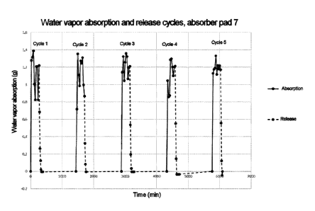
Figure 1: Water vapor absorption of an inventive absorber pad
Figure 2: Water vapor absorption of a noninventive absorber pad
Figure 3: Sound-absorbing properties of an inventive absorber pad
Figure 4: Schematic representation of the cross section of a seam 5
Description of figures:
Figure 1 shows the water vapor absorption of an absorber pad according to the
present disclosure. It is apparent that the water vapor is absorbed very
rapidly.
The water vapor absorption is already at equilibrium after 30 minutes. On this
Date Recue/Date Received 2023-05-10
17
point it is notable that drying again also proceeds very rapidly and is
virtually
complete.
Figure 2 shows the water vapor absorption of an absorber pad not according to
the present disclosure. It is apparent that the water vapor is absorbed much
more slowly. The water vapor absorption is at equilibrium after 90 minutes at
the earliest. Moreover, drying again is not complete even after 20 h.
Figure 3 shows the sound-absorbing properties of a number of absorber pads
according to the present disclosure. It is apparent that all of the absorption
pads
according to the present disclosure have a good absorption coefficient.
In figure 4 the cross section of a seam is represented. The seam is in the
form
of a weld seam. The thickness of the weld seam decreases in the direction of
the edge. Correspondingly, the density of the weld seam increases in the
direction of the edge. This transition is continuous.
The present disclosure is elucidated in more detail below with a number of
examples:
Example 1: Production of composite materials which can be used according to
the present disclosure
Various composite materials and absorber pads which can be used according
to the present disclosure are produced.
Materials used were as follows:
Microfiber spunbond: Spunbonded polyamide/polyester microfiber web
"EvoIon 0" ; 200 g/m2.
Superabsorbent particles 1: Partly neutralized and crosslinked
polyacrylic acid, produced in a bulk
polymerization process, having a
Date Recue/Date Received 2023-05-10
18
particle size distribution d50 of 50 pm ¨
1000 pm, application weight 15 g/m2.
Superabsorbent particles 2: Partly neutralized and crosslinked
polyacrylic acid, produced in an inverse
suspension polymerization process,
having a particle size distribution d50 of
50 pm ¨ 1000 pm, application weight
g/m2.
Water-soluble distribution lamina 1: Water-soluble, partially hydrolyzed
10 polyvinyl alcohol with an application
weight of 20 g/m2
Water-soluble distribution lamina 2: Water-soluble starch with an
application
weight of 20 g/m2
15 The table below shows the layer construction used
Composi Liquid-distributing layer Liquid-absorbing Backing layer
te layer
material
1 - Water-soluble distribution lamina Superabsorbent
Microfiber spunbond
1 in combination with particles 1 fixed
- non-water-soluble distribution with PVA on
layer backing layer
microfiber spunbond
2 - Water-soluble distribution lamina Superabsorbent Thermally
bonded PES
1 in combination with particles 2 fixed staple fiber
nonwoven,
- non-water-soluble distribution with PVA on 40 g/m2
layer (thermally bonded PES staple backing layer
fiber nonwoven, 40 g/m2)
3 - Water-soluble distribution lamina Superabsorbent
Binder-bound PES
2 in combination with particles 1 fixed staple fiber
nonwoven,
with PVA on 40 g/m2
backing layer
Date Recue/Date Received 2023-05-10
19
- non-water-soluble distribution
layer (binder-bound PES staple
fiber nonwoven, 40 g/m2)
4 - Water-soluble distribution lamina Superabsorbent
Thermally bonded PP
1 in combination with particles 2 fixed spunbond, 60
g/m2
- non-water-soluble distribution with PVA on
layer (thermally bonded PP backing layer
spunbond, 60 g/m2)
- water-soluble distribution lamina 1 Superabsorbent Binder-bound PES
particles 2 fixed staple fiber nonwoven,
with PVA on 40 g/m2
backing layer
The joining of the layers takes place as follows:
5 First of all the backing layer is taken and is coated with the water-
soluble
distribution lamina and with the superabsorbent particles. Subsequently, if
used,
the water-insoluble distribution lamina is added.
The composite materials 1 to 5 are each arranged between two thermally
weldable layers (bag layers, 80 g/m2 microfiber spunbond), whose edges
project beyond the composite materials all round, and the edges of these
layers
are welded to form an absorber pad. The step of cutting to size may take place
before or after welding.
In another embodiment a plurality (2 ¨ 5) of composite materials 1-5 are
welded
in to give absorber pads.
In another embodiment the composite materials 1 ¨ 5 are welded all round
thermally at the edge, and the non-water-soluble distribution layer and the
backing layer melt, with partial penetration of the liquid-absorbing layer,
and
thereby join all of the layers thermally to one another.
Date Recue/Date Received 2023-05-10
20
In another embodiment two composite materials 5 are arranged in such a way
that the liquid-absorbing layers are facing one another. The resulting
composite
is welded all round thermally at the edge, and the carrier layer melts, with
partial
penetration of the liquid-absorbing layers, and thereby joins all of the
layers
thermally to one another. The step of cutting to size may take place before or
after welding. This produces absorber pad 6a.
In another embodiment four composite materials 5 are arranged in such a way
that the backing layers form the outer layers. The resulting composite is
welded
all round thermally at the edge, and the backing layers melt, with partial
penetration of the liquid-absorbing layers, and thereby join all of the layers
thermally to one another. The step of cutting to size may take place before or
after welding. This produces absorber pad 6b.
In another embodiment six composite materials 5 are arranged in such a way
that the backing layers form the outer layers. The resulting composite is
welded
all round thermally at the edge, and the backing layers melt, with partial
penetration of the liquid-absorbing layers, and thereby join all of the layers
thermally to one another. The step of cutting to size may take place before or
after welding. This produces absorber pad 6c.
In another embodiment two composite materials 5 are arranged in such a way
that the liquid-absorbing layers are facing one another. Arranged between
these
liquid-absorbing layers is an adhesive nonwoven (copolyester nonwoven,
g/m2, Smp. 100-110 C). The resulting composite is welded all round
thermally at the edge, and the adhesive nonwoven melts, with partial
penetration of the liquid-absorbing layers, and thereby joins all of the
layers
thermally to one another. This produces absorber pad 7.
Example 2: Testing the absorption capacity of an absorber pad according to
the present disclosure
Date Recue/Date Received 2023-05-10
21
The absorption capacity of the absorber pad 7 was tested according to
DIN 53923 using fully demineralized water. It was found that the absorber pad
7
has a good water absorption of 8.7 kg/m2. As part of the test according to
DIN 53923, the absorber pad 7 is suspended freely hanging in the fully swollen
state for 30 seconds. The water loss here is 550 g/m2, which thus corresponds
to very good retention. The absorber pad could also be dried simply, without
heating, which shows that it is also capable of reversible binding of water.
As a
result of the all-round welding, swelling was readily controllable and a
blocking
effect could be prevented through the use of distributor layers. Dusting could
be
prevented by the fixing of the superabsorbent particles.
Example 3: Testing the water vapor absorption of an absorber pad according
to the present disclosure
The water vapor absorption of absorber pad 7 was tested. For this purpose the
absorber pad was stored in a conditioning chamber for a period of 270 minutes
at 90% atmospheric humidity and 30 C. The increase in weight was determined
gravimetrically every 30 minutes over a period of 270 minutes. The absorber
pad 7 was subsequently dried at room temperature and the decrease in weight
was determined gravimetrically. This procedure was repeated five times and is
shown in figure 1.
It is found that the water vapor absorption is very rapid. Water vapor
absorption
is already at equilibrium after 30 minutes. In this regard it is noteworthy
that the
drying again is also very rapid and is virtually complete.
Example 4: Testing the water vapor absorption of an absorber pad not
according to the present disclosure
The water vapor absorption of an absorber pad not according to the present
disclosure was tested. The absorber pad consists of a nonwoven bag filled with
Date Recue/Date Received 2023-05-10
22
1 g of loose superabsorbent particles 2. The increase in weight was determined
gravimetrically every 30 minutes over a period of 270 minutes. The absorber
pad not according to the present disclosure was subsequently dried at room
temperature for 20 h and the decrease in weight was determined
gravimetrically. This procedure was repeated five times and is shown in
figure 2.
It is found that the absorption of water vapor is much slower. The water vapor
absorption is at equilibrium after 90 minutes at the earliest. Moreover,
drying
again is still incomplete after 20 h.
Example 5: Testing the sound-absorbing properties of an absorber pad
according to the present disclosure
The sound-absorbing properties of three different absorber pads 6a, 6b, 6c
were determined according to EN ISO 354:2003. The results are shown in
figure 3. It is apparent that all of the absorption pads according to the
present
disclosure have a good absorption coefficient.
Date Recue/Date Received 2023-05-10