Note: Descriptions are shown in the official language in which they were submitted.
Magnetic Position Measurement System with Interference
Reduction
CLAIM OF PRIORITY
This application claims priority under 35 U.S.C. 119(e) to U.S. Patent
Application Serial No. 63/156,695, filed on March 4, 2021.
TECHNICAL FIELD
This disclosure relates to electromagnetic tracking systems. More
specifically,
this disclosure relates to reducing interference with nearby instrumentation
in a tracking
environment.
BACKGROUND
Electromagnetic Tracking (EMT) systems are used to aid in locating instruments
and anatomy in medical procedures. These systems utilize a magnetic
transmitter in
proximity to a magnetic sensor. The sensor can be spatially located relative
to the
transmitter.
SUMMARY
An Electromagnetic Tracking (EMT) system can be used to track the position
and/or orientation of a sensor (e.g., the pose) relative to a transmitter. The
EMT system is
configured to transmit tracking signals including time division multiplexed
(TDM)
alternating current (AC) signals. This includes transmitting sinusoid pulses
or bursts from
each of a plurality of transmitting coils by cycling each transmitter ON and
OFF. The
EMT system includes a receiver configured to receive the sinusoid pulses or
bursts. A
coil in the receiver produces a signal in response to receiving the
transmitted signal. The
signal produced by the receiver is associated with one of the transmitters.
Based on
receiver signals representing each of the transmitted signals, the EMT system
can
determine an approximate pose of a tracked object at the location of the
receiver.
1
Date Recue/Date Received 2022-02-21
For transmission of the TDM-AC signal, the EMT system multiplies a shaping
signal with the sine burst signal. The shaping signal is used to alternate
each transmitter
between the ON state and the OFF state. The EMT system forms the shaping
signal to
create a signal envelope for the sine burst. Rather than a square-wave shaping
signal, the
EMT system is configured to produce a shaping signal that ramps up from OFF to
fully
ON and ramps down from fully ON to OFF. The EMT can form the shaping signal by
applying one or more filters to the shaping signal. The shaping signal enables
the
transmitter to transmit a sine burst having a maximum signal amplitude for a
period of
time while also reducing transmitted harmonic signals resulting from cycling
between
OFF and ON states at a particular frequency. The exact shape of the shaping
signal is
tuned to reduce the harmonic signal amplitude while also preserving the sine
burst
amplitude such that the sine burst is strong enough to generate a signal at
the receiver.
The EMT system includes sensor coils having magnetic core designs. These cores
can be smaller relative to air-cores that are linear while still producing a
relatively strong
signal suitable for tracking purposes such as for use in medical catheters.
The relative
smaller size of the receiver having a coil with a magnetic core enables the
receiver to be
smaller than the receiver would be using coils with air cores, which produce a
linear
response but generally require a relatively stronger transmitted signal.
The EMT system uses TDM-AC transmitted signals that are shaped as previously
described to enable use of smaller, non-linear receiver coils in the receiver.
This
combination of features provides one or more of the following advantages. The
EMT
system does not cause intermodulation distortion (IMD) in the coils of the
receiver. This
is because, rather than transmitting EM signals at multiple frequencies using
a division
multiplexed (FDM)-based transmission, the EMT system transmits EM signals
using
TDM-AC-based transmissions.
IMD can cause tracking errors in the EMT system. The use of TDM-AC signals
allows the use of magnetic cores (which provide a stronger response than air
cores) in
receive coils. The use of shaped TDM-AC signals by the EMT system reduces or
eliminates harmonic signals (e.g., transmitted signals that are at different
frequencies than
the sinusoid burst frequency ¨ also called a center frequency or selected
frequency). As
2
Date Recue/Date Received 2022-02-21
previously described, the harmonic frequencies are an artifact of cycling the
transmitters
between OFF and ON states to perform TDM-AC transmission.
The shaping signal causes the transmitters to "ramp up" and "ramp down"
transmission of the respective TDM-AC signals. The shaping signal reduces the
strength
of transmitted harmonic frequencies while preserving signal strength for the
selected
center frequency. The reduction in the strength of transmitted harmonic
signals reduces
interference that may occur with the operation of nearby electronic
instrumentation, such
as electrocardiographs (EKGs) that are normally sensitive to signals below
1KHz, or for
other biomedical instrumentation (e.g. medical impedance location devices),
which are
generally susceptible to noise above 10KHz.
Additionally, the shaped signal prevents induced IMD in EMT ferrite-core
sensors
due to the harmonics of the TDM-AC waveform (i.e., a sinusoid pulse or burst).
This
preserves EMT system performance. The shaped transmitter signals benefit
overall EMT
system performance (e.g., system noise) by reducing the effects of IMD in EMT
ferrite-
core sensor inputs
The one or more advantages and/or features previously described can be
realized
by one or more of the following embodiments.
In an aspect, a system includes a transmitter that includes a plurality of
coils. The
transmitter is configured to generate magnetic field signals. The system
includes a sensor
that includes a receiver coil. The sensor is configured to provide sensor
signals that
correspond to the magnetic field signals generated by the transmitter. The
sensor signal is
configured to produce an output response indicative of the location of the
sensor relative
to the transmitter based on the magnetic field signals generated by the
transmitter. The
system includes a computing device in communication with the transmitter and
the sensor.
The computing device is configured to determine a frequency for generating at
least a
portion of a magnetic field signal using a transmitter coil of the plurality.
The computing
device is configured to configure a time-division multiplexed (TDM) control
signal for
controlling transmissions of the magnetic field signal from the transmitter
coil, the TDM
control signal configured to cause the transmitter coil to transmit bursts of
the magnetic
field signal at the frequency. The computing device is configured to configure
a filter for
3
Date Recue/Date Received 2022-02-21
filtering the TDM control signal, the filter configured to shape each burst to
reduce or
eliminate a harmonic artifact of the bursts. The computing device is
configured to cause
the transmitter coil to generate the shaped bursts of the magnetic field
signal. The
computing device is configured to receive, from the sensor, a sensor signal
that corresponds
to the magnetic field signal, the sensor signal including the output response
indicative of
the location of the sensor relative to the transmitter.
In some implementations, the filter comprises a low-pass filter that filters a
step
function and wherein the computing device is further configured to multiply
the magnetic
field signal with the step function to shape the bursts.
In some implementations, the magnetic field signal comprises a TDM alternating
current (TDM-AC) signal.
In some implementations, the receiver coil comprises a core that has a
relative
magnetic permeability value greater than 1. In some implementations, the core
comprises
one of a ferrite material or a permalloy material.
In some implementations, each coil of the plurality of coils in the
transmitter is
configured to generate a respective magnetic field signal at a respective
frequency value
that is different from the other coils of the plurality. In some
implementations, the
respective magnetic field signal of each coil is shaped by a filter signal to
prevent
interference of the respective magnetic field signal of each coil with
adjacent measurement
modalities of the other coils of the plurality.
In some implementations, the sensor signal comprises a voltage that is
generated
based on interaction between the sensor and the magnetic field signal
generated by the
transmitter. In some implementations, a value of the voltage is indicative of
at least one of
an orientation and a position of the sensor relative to the transmitter.
In some implementations, filter is configured to reduce the harmonic artifacts
received at another electronic device in the environment to below a threshold
level
specified for the other electronic device.
In some implementations, the sensor is selected from a group comprising: a
hall-
effect sensor, a magnetoresistive sensor, a magneto-optical sensor, and a
fluxgate
magnetometer.
4
Date Recue/Date Received 2022-02-21
In a general aspect, a method for reducing interference caused by a magnetic
tracking system includes determining a frequency for generating at least a
portion of a
magnetic field signal using a transmitter coil of a plurality of transmitter
coils. The method
includes configuring a time-division multiplexed (TDM) control signal for
controlling
transmissions of the magnetic field signal from the transmitter coil, the TDM
control signal
configured to cause the transmitter coil to transmit bursts of the magnetic
field signal at the
frequency. The method includes obtaining threshold data representing a
threshold
interference level for one or more devices in an environment of the magnetic
tracking
system. The method includes configuring a filter for filtering the TDM control
signal, the
filter configured to shape each burst to reduce a harmonic artifact of the
bursts below the
threshold interference level of the threshold data. The method includes
causing the
transmitter coil to generate the shaped bursts of the magnetic field signal.
The method
includes receiving, from a sensor, a sensor signal that corresponds to the
magnetic field
signal, the sensor including the output response indicative of the location of
the sensor
relative to the transmitter.
In some implementations, the threshold data are obtained from the one or more
other devices during operation of the magnetic tracking system, and wherein
the filter is
configured to shape each burst for a next transmission in response to
obtaining the
threshold data.
In a general aspect, a method includes determining a frequency for generating
at
least a portion of a magnetic field signal using a transmitter coil of a
magnetic tracking
system. The method includes configuring a time-division multiplexed (TDM)
control
signal for controlling transmissions of the magnetic field signal from the
transmitter coil,
the TDM control signal configured to cause the transmitter coil to transmit
bursts of the
magnetic field signal at the frequency. The method includes configuring a
filter for
filtering the TDM control signal. The filter is configured to shape each burst
to reduce or
eliminate a harmonic artifact of the bursts. The method includes causing the
transmitter
coil to generate the shaped bursts of the magnetic field signal. The method
includes
receiving, from a sensor of the magnetic tracking system, a sensor signal that
corresponds
5
Date Recue/Date Received 2022-02-21
to the magnetic field signal, the sensor signal including the output response
indicative of
the location of the sensor relative to the transmitter.
In some implementations, the filter comprises a low-pass filter that filters a
step
function. The method further includes multiplying the magnetic field signal
with the step
function to shape the bursts.
In some implementations, the magnetic field signal comprises a TDM alternating
current (TDM-AC) signal. In some implementations, a receiver coil of the
sensor
includes a core that has a relative magnetic permeability value greater than
1. In some
implementations, the core includes one of a ferrite material or a permalloy
material.
In some implementations, the filter is configured to reduce the harmonic
artifacts
received at another electronic device in the environment to below a threshold
level
specified for the other electronic device.
In some implementations, the sensor is selected from a group comprising: a
hall-
effect sensor, a magnetoresistive sensor, a magneto-optical sensor, and a
fluxgate
magnetometer.
The details of one or more embodiments of the subject matter described herein
are
set forth in the accompanying drawings and the description below. Other
features,
objects, and advantages of the subject matter will be apparent from the
description and
drawings, and from the claims.
DESCRIPTION OF DRAWINGS
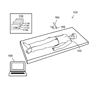
FIG. 1 is an illustration of an EMT system that includes a sensor and a
transmitter.
FIG. 2 shows a block diagram of the EMT system of FIG. 1.
FIGS. 3-4 show example filters.
FIG. 5 shows an example of a shaped transmitted magnetic field signal.
FIGS. 6-7 show examples of an electrocardiogram (EKG) response.
FIG. 8 shows a graph representing IMD reduction for a sensor of the EMT system
of FIGS. 1-2.
FIGS. 9-10 are flow diagrams that illustrates a process for interference
reducing
in an EMT system.
6
Date Recue/Date Received 2022-02-21
FIG. ills an example computing system.
DETAILED DESCRIPTION
An EMT system includes a system configured to track a location of an object in
an environment. For example, the EMT system can be used in surgical settings
to track a
piece of medical equipment, a robotic arm, etc., thereby allowing its
respective three-
dimensional (3D) location and orientation to be known to a medical
professional (e.g., a
surgeon) during a medical procedure. Such electromagnetic tracking can be used
for
guidance purposes in image-guided procedures, and in some cases may allow for
reduced
reliance on other imaging modalities, such as fluoroscopy, which can expose
the patient
to health risk of ionizing radiation.
In general, a transmitter having one or more coils is configured to generate
an
alternating current (AC) EM field. A sensor having one or more coils that is
in proximity
to the generated EM field is configured to measure characteristics of the
generated EM
field. The measurements are based on the position and orientation of the
sensor relative to
the transmitter. For example, when the sensor is located at a particular
position and
orientation, the EM field at that particular location may have particular
characteristics.
The sensor can measure the characteristics of the EM field and provide such
measurements to a computing device in the form of a sensor signal. Using
information
related to the generated EM field and the sensor signal received from the
sensor, the
computing device can determine the position and/or orientation of the sensor
(and, e.g.,
the position and/or orientation of a medical device in which the sensor is
incorporated).
Generally, a plurality of transmitter coils are included in the transmitter of
the
EMT system to increase the tracking degrees of freedom (DoF), as further
described in
reference to FIG. 1. The EMT system is configured to avoid distortions, such
as inter-
modular distortion (IMD) in the receiver coil(s) caused by transmitting at
multiple
frequencies during frequency division multiplexed (FDM) operation. To avoid
distortions
such as IMD distortion that can occur in FDM based systems, the EMT system is
configured to operate using time division multiplexed alternating current (TDM-
AC)
transmissions.
7
Date Recue/Date Received 2022-02-21
To receive the TDM-AC transmissions, EMT sensor coils can include magnetic
cores. The magnetic (e.g., ferrite, permalloy, etc.) core of the coil
increases the sensitivity
of the receiver coil in comparison with an air core for the sensor coil. A
response signal
generated by the sensor coil includes a signal produced by the receiver coil
in response to
receiving a magnetic signal from the transmitter coil(s). A linear response
includes an
output signal that is based on a linear function of the input signal. A non-
linear response
includes an output signal that is a non-linear function of the input signal.
Sensor coils including an air core design are relatively large (e.g., compared
to
sensor coils including metal cores). The relatively large size of sensors
including coils
with air cores is impractical for some purposes, such as use with various
medical
catheters. In contrast, the sensor of the EMT system can be relatively smaller
using a non-
linear core, such as a magnetic core (e.g., a metal with a relative magnetic
permeability
value substantially above 1). Non-linear cores can include ferrite cores,
permalloy cores,
and similarly magnetic materials as core materials.
Non-linear cores can provide a relatively strong inductive response in a
receiver
coil of the sensor, enabling the sensor to be more sensitive to transmitted
TDM-AC
signals. When operating using TDM-AC transmissions, harmonic signals of the
TDM-AC
transmitted frequencies may be detectable by nearby electronic instrumentation
as
unwanted noise. The harmonic signals can be artifacts of the cycling of the
transmitters
between ON and OFF states for the TDM-AC transmission. The signal harmonics
may
interfere with the operation of nearby electronic instrumentation. For
example,
equipment, such as electrocardiographs (EKGs) that are normally sensitive to
signals
below 1 kilohertz (KHz), can experience interference. In another example,
biomedical
instrumentation devices, such as medical impedance location devices, which are
generally susceptible to noise above 10KHz can experience interference.
To reduce or eliminate the harmonic signal artifacts, the EMT system applies a
shaping (or modulating) excitation signal to limit (e.g., spectrally) the
emitted magnetic
signals of the EM transmitters. The modulated or shaped excitation signal
minimizes or
eliminates interference with other biomedical instrumentation in the tracking
environment by limiting the signal strength of the harmonic signals. The
shaping signal
8
Date Recue/Date Received 2022-02-21
causes an amplitude of the sine burst to ramp up and ramp down during each TDM
cycle,
rather than a near-instantaneous OFF/ON switching of a square wave excitation
signal.
The exact shape of the shaping signal depends on receiver sensitivity and the
particular
application for the tracking being performed.
FIG. 1 presents an exemplary embodiment of the EMT system 100, which can be
used for image-guided medical procedures performed on a patient 102. The EMT
system
100 may include a freely moving medical instrument, which is a tracked object
104 by
the EMT system. The tracked object 104 can include any manner of surgical
tools and
devices for use in medical treatment. The EMT system 100 permits targeting of
an
anatomical organ, structure, or vessel for visualization, diagnostic,
interventional
purposes, etc. Instruments for use in the EMT system 100 typically include one
or more
magnetic sensors including one or more coils. The sensor 106 may be embedded
in a
channel or affixed to a tip of the tracked object 104. The particular sensor
106 employed
by the EMT system 100 may be determined by the procedure type and/or the
measurement performance requirements. In the illustrated example, the sensor
106 is
connected to an electronic unit or a computing device, such as a processing
device 108,
via a wireless connection. Under control of circuitry for energizing magnetic
fields, the
sensor 106 measures its instantaneous position (x, y, z) and orientation
angles (azimuth,
altitude, roll) in three-dimensional space relative to a transmitter 110 and
sends the
measurement signal to the processing device 108 for analysis.
Generally, the sensor 106 can include a magnetic core for the receiver coil
122.
The magnetic core includes a high magnetic permeability relative to the
surrounding air,
and thus results in a stronger inductive response at the coil. This enables
the receiver coil
122 to operate in lower-energy environments or be reduced in size to create a
response
signal that is useful for magnetic tracking. For example, a ferrite core (or
other metal) can
be used in the sensor 106 to reduce size of a receive coil of the sensor
relative to an air
core for a receive coil. The reduced size can be useful for including a
smaller sensor 106
in some medical instruments that may be tracked objects 104. For example,
ferrite core
receivers are used in the sensor 106 for use inside or near a patient, such as
for a catheter,
endoscope, or other such medical instrument.
9
Date Recue/Date Received 2022-02-21
Like the sensor 106, the particular transmitter employed by the EMT system 100
may be determined by the procedure type, measurement performance requirements,
etc.
In the an example, the transmitter 110 may be a three-axis magnetic
transmitter that
includes three transmitter coils ¨ an X-coil for generating an X-component of
an EM
field, a Y-coil for generating a Y-component of the EM field, and a Z-coil for
generating a
Z-component of the EM field. That is, each transmitter coil 114a-n is
configured to
provide a portion of the EM field. In some implementations, the transmitter
coils are
formed as a concentric, collocated set of transmitter coils 114a-n.
Additional transmitter coils 114a-n are added to add degrees of freedom for
tracking the tracked object 104. For example, fourth and fifth coils can be
added for
detecting pitch and yaw of the tracked object 104. To achieve increased
tracking
accuracy, there can include more than five transmitter coils 114a-n. For
example, six,
seven eight, or up to twelve or more transmitter coils 114a-n can be used.
Additional
transmitter coils 114a-n may increase precision of the EMT system 100.
The transmitter 110 is typically fixed in space beside, above, or beneath the
patient or on medical equipment, where it acts as the reference frame for the
measurements provided by the sensor 106. In some implementations, the
transmitter 110
may be designed to minimize and/or negate the effect of distorters beneath its
surface,
such as procedural tables and/or equipment. The measurements provided by the
sensor
106 and transmitter 110 provide sufficient information to navigate the
instrument 104
outside or within the body of the patient 102 for diagnostic and
interventional purposes,
in some cases while providing visual feedback.
In some implementations, the processing device 108 is an imaging computer that
is configured to provide imaging capabilities to the EMT system 100. The
imaging
processing device 108, which in the illustrated example is in wireless
communication
with the sensor 106 and transmitter 110, is configured to store pre-acquired
or intra-
operative images of the patient 102 in an image database. Such images may then
be input
to imaging software for registration and visualization purposes. During the
medical
procedure, the three-dimensional location of the instrument 104 can be tracked
relative to
the anatomy of the patient 102 and the pre-acquired or inter-operative images
and shown
Date Recue/Date Received 2022-02-21
in real time on a display of the processing device 108. When the instrument
104 is
advanced toward the target of interest within the body of the patient 102, the
transmitter
110 can be activated and energized, thus producing measurable signals (e.g.,
voltage
signals) in the sensor 106. These signals are processed and the three-
dimensional location
is computed for transmission to the processing device 108. In some
implementations, the
processing device 108 includes a guidance electronics unit that is configured
to process
the voltages in order to provide the three-dimensional location.
In some implementations, before the start of the procedure, one or more
protocols
are implemented. One protocol may initialize the instrument 104 and sensor 106
to
prepare for tracking by the processing device 108. Configuration data, such as
instrument
type, part number, sensor location in the instrument, calibration data, etc.
may be stored
in a memory of the processing device 108. From this point forward, the EMT
system 100
may automatically provide the imaging software with specific configuration of
the
attached instrument 104. In such implementations, no manual entry of medical
instrument
data by the physician may be required. Another protocol may correlate the
instrument
104, imaging modality, and patient reference frames so that the physician can
guide the
instrument intuitively within the patient 102 by following three-dimensional
visualization
cues. Once these protocols have been accomplished, the processing device 108
can
continuously receive instrument guidance data at the patient 102 and align the
data with
locations on the display of the processing device 108. In this manner, as the
physician
moves the tracked object 104 (e.g., a medical instrument) to a target within
the body of
the patient 102, the physician also sees an image on the display of an icon
that
corresponds to the instrument 104 relative to target images of the patient
102. The control
of the guidance data and integration with scanned images may be a function of
the three-
dimensional software operable on the processing device 108.
In general, the EM field generated by the transmitter 110 has characteristics
that
can be measured by the receive coils of the sensor 106. For example, as the
sensor 106
changes position in proximity to the transmitter 110, the x-, y-, and z- coils
can each
measure characteristics of the X-component, the Y-component, and the Z-
component of
the EM field, providing nine total components of the sensor signal. A matrix
11
Date Recue/Date Received 2022-02-21
representation of the sensor signal is sometimes referred to as an S-matrix
(e.g., a 3 x 3
matrix) in which the columns represent the X-, Y-, and Z- coils of the
transmitter 110 and
the rows represent the x-, y-, and z- coils of the sensor 106.
The receiver coil 122 of the sensor 106 has a non-linear response, as
previously
described, because the coil has a magnetized core (e.g., a ferrite core or
other magnetized
metal core). For example the materials can include ferrite materials, a
permalloy, or other
similar material. In generally, a relatively long and narrow magnetized
material (e.g.,
having a length to width ratio greater than 1) can be used for the core of the
receiver coil
122 of the sensor 106. In another example, a non-linear core material having
other shapes
(e.g., a cube) can be used for the core of the receiver coil. The EMT system
100 uses
time-domain multiplexing to control transmitted EM signals from each of the
transmitter
coils 114a-n of the transmitter 110. For example, the transmitter 110 can
include an X-coil
operating at carrier frequency A, a Y-coil is operating at carrier frequency
B, and a Z-coil
can operate at carrier frequency C.
In some implementations, the sensor 106 includes other types of non-linear
sensing elements configured to measure magnetic field strength/magnetic flux
density of
the transmitted signal for determining the position of the sensor relative to
the transmitter
110. For example, the sensor 106 can include a hall-effect sensor. In another
example, the
sensor 106 includes a magnetoresistive sensor configured to measure a changing
resistance of a material under the influence of magnetic fields. In another
example, the
sensor 106 includes a magneto-optical sensor. In another example, the sensor
includes a
fluxgate magnetometer. Each of these devices can have a non-linear response to
the
transmitted magnetic signal.
Each coil is configured for emitting TDM-AC signals. These signals can each
include a sinusoid pulse or burst. The EMT system 100 applies a bandwidth-
limiting
window function to each EM transmitter signal burst or sinusoid pulse. The
window
function reduces the spectral spread from the center frequency of the
transmission. The
window function is configured to eliminate signal harmonics and therefore
reduce or
eliminate interference with other medical devices and/or equipment, as
previously
described.
12
Date Recue/Date Received 2022-02-21
The shaping of the excitation signal performed by the EMT system 100 is now
described. To operate the transmitter 110, a filter is placed on each coil
drive of the
transmitter. This filter shapes each sine pulse or burst during the TDM-AC
transmission
for a transmitter. The controller of the EMT system 100 causes a square wave
(e.g.,
ON/OFF) control signal to be sent to the transmitter coils 114a-n to control
how the coils
of the transmitter 110 transmit the carrier signal. The square wave control
signal is
shaped by the filter to cause the signal to ramp up from OFF to ON and ramp
down from
ON to OFF. The shaped signal reduces a rate of change of the excitation signal
between
the OFF and ON portions of the signal. The reduced change causes the amplitude
of
harmonic artifacts of the TDM-AC transmission to be reduced or eliminated.
This
reduces distortion in tracking the tracked object 104 because the sensor 106
does not
receive the harmonic artifacts (or receives artifacts of reduced amplitude)
that can
interfere with tracking.
The coils of the transmitter 110 thus each transmit a waveform composed from
several elements. A signal is transmitted at a desired frequency (sometimes
called a center
frequency). In an example, the frequency can be about 3200 Hz, though the EMT
system
100 can adjust the frequency to other values. The signal is shaped by the
control signal
(or excitation signal) by multiplying the signals. The EMT system 100 applies
a filter to
the control signal, which is originally a square wave. The filter controls how
quickly or
slowly the sine wave amplitude is ramped up and down for each cycle. The
faster the
transmitter is turned completely on and off for each cycle, the higher the
root-mean-
squared (RMS) signal strength value is at the desired frequency. A stronger
signal is
easier to distinguish from noise by the receiver coil(s) of the sensor 106.
Each coil of the
transmitter 110 thus transmits a signal within a "signal envelope" shaped by
the filtered
control signal. Examples of these shaped signals are subsequently described in
reference
to FIGS. 2-4.
The shaped signals reduce harmonic artifacts of the transmitted TDM-AC
signals.
The receiver coils of the ETM system 100, which have increased sensitivity due
to their
magnetic cores, can receive the TDM-AC signal and distinguish the desired
frequency
from noise of the environment and the harmonic artifacts, now reduced in
amplitude. This
13
Date Recue/Date Received 2022-02-21
configuration bypasses the problem of IMD that would be caused in the receiver
coils if a
FDM approach were used in the EMT system 100.
The filter used to shape the transmitted signals from the respective
transmitter
coils 114a-n can be configured based on the parameters of the non-linear core
of the
receiver coil 122 of the sensor 106. In some implementations, the EMT system
100
adjusts the size of the envelope based on the permitted signal strength of the
harmonic
artifacts. The EMT system 100 can increase the RMS signal level of the
transmission by
the transmitting coils 114a-n by decreasing an amount of time needed to switch
from the
OFF state to the ON state, or vice versa. This also increases the strength of
the harmonic
artifacts. If the amplitudes of the harmonic artifacts are below a threshold
for the receiver
coil 122, the RMS signal level can be increased, which enables a stronger
signal
transmission at the selected frequency of the sine burst. This tuning can be
performed to
ensure that the transmitted signal is strong enough for use in operation of
the EMT
system 100 in a particular environment and to ensure that the harmonic
artifact threshold
is not exceeded in a given receiver coil 122. For example, the signal strength
may be
increased by the EMT system 100 for operation at greater ranges between the
transmitter
110 and the sensor. In some implementations, the signal strength may be
increased for
operation in the presence of other distortions to the signal. In a specific
example, the
EMT system 100 is configured to communicate with one or more other systems in
the
environment of the EMT system. The one or more other systems or devices may
send
information describing interference thresholds for their respective
operations. The
information represents a maximum tolerable signal strength at one or more
frequencies
corresponding to the harmonic signal before the other system or device
experiences
degraded performance from the interference. In response, the EMT system 100 is
configured to adjust the envelope to reduce interference below the received
threshold
levels while still maximizing the signal strength. In some implementations,
the EMT
system 100 adjusts the signal envelope in real time or near real time (e.g.,
adjusts for a
subsequent transmission cycle) based on the obtained threshold information. In
some
implementations, the EMT system 100 stores the threshold information for one
or more
14
Date Recue/Date Received 2022-02-21
other devices and retrieves that information for use during envelope
construction at a
later time (e.g., subsequent operations).
The EMT system 100 causes each transmitter coil 114a-n of the transmitter 110
to
transmit a shaped signal that is configured to avoid interference with
adjacent
measurement modalities. The sensor 106 is configured to receive the signals
from the
respective transmitter coils 114a-n of the transmitter 110 without harmonic
artifacts or
with a minimized harmonic artifacts that does not result in tracking errors or
interference
with other systems in the tracking environment. For example, for a twelve
transmitter coil
system, the sensor 106 is configured to receive twelve signals at twelve
respective
frequencies. Each of these transmissions is shaped so that the harmonic
artifacts avoid
interference with the other transmissions. If more coils are included in the
transmitter
110, a size of each shaped envelope for each transmission can be reduced to
avoid
interference with adjacent modalities while maintaining sufficient signal
strength for the
selected frequency.
Turning to FIG. 2, a block diagram of the EMT system 200 is shown. The EMT
system 200 can be substantially similar to the EMT system 100 described in
reference to
FIG. 1. The processing device 208 of the EMT system 200 can include a tracking
logic
engine 218, a TDM engine 212, and a signal processing engine 216. The tracking
logic
engine 218 is configured to determine an approximate position and orientation
of the
tracked object 204 based on signals received from the sensor 206. As
previously
described, the signals received from each of the transmitter coils 214a-n of
the transmitter
210 are transmitted to the sensor 206. The sensor 206 receives the transmitted
signals
with a receiver coil 222 that is generally non-linear. The sensor 206 is
configured to send
the measured signals to the processing device 208, typically over a wireless
communications link. The processing device 208 receives the measured signals
from the
sensor 206 at the signal processing engine 216. The signal processing engine
216 is
configured to receive the signal from the sensor and send a digital
representation of the
signal to the tracking logic engine 218. The tracking logic engine 218
determines the
position and orientation of the tracked object 204 in the environment of the
EMT system
200 based on parameters of the EMT system, such as which transmitter coil 214a-
n is
Date Recue/Date Received 2022-02-21
associated with the received signal, hardware calibration parameters of the
system,
known environmental distortions (if any), and so forth.
The tracking logic engine 218 includes signal shaping logic 220. The signal
shaping logic 220 is configured to shape the transmission from each
transmitter coil to
reduce or eliminate harmonic artifacts, as previously described. The signal
shaping logic
controls what filter parameters are used to drive the transmitted signals from
each of the
transmitter coils 214a-n.
The TDM engine 212 is configured to multiply the shaping signal with the
sinusoid signals generated by each of the transmitter coils. The TDM engine
212 causes
each transmitting coil to transmit shaped sinusoid bursts that are shaped to
reduce or
eliminate harmonic artifacts, as previously described. The TDM engine 212
controls the
transmitter coils so that each transmitter coil operates in turn. The TDM
engine cycles
through the transmitter coils so that each transmitter coil 214a-n transmits a
shaped burst
for each transmission cycle to be received by the receiver coil 222.
As previously described, the transmitter coils 214a-n each transmit a shaped
signal including a sine pulse having a particular frequency. The number of
transmitter
coils 214a-n can vary depending on the precision required for tracking the
tracked object
204. The number of transmitter coils 214a-n can include 5, 6, 8, 12, or more.
As previously described, the receiver coil 222 of the sensor 206 is generally
non-
linear. The non-linear receiver coil 222 of the sensor 206 can be smaller than
linear coils
with similar response sensitivity. The receiver coil 222 can include a
magnetic core, as
previously described in relation to FIG. 1.
Turning to FIG. 3, an example graph 300 shows filter characteristics for
shaping
the signals transmitted by the transmitter coils 114a-n. In this example, a 69
tap Dolph-
Chebychev filter is used to window the transmitter sine burst to restrict the
bandwidth
about the selected transmission frequency of each transmitter coil. Graph 300
shows the
simulated frequency characteristic of the filter.
FIG. 4 shows an example graph 400 illustrating a frequency response of an
envelope reconstruction device (e.g., a filter). The envelope reconstruction
device
includes circuitry configured to recover the carrier envelope signal and
perform a filtering
16
Date Recue/Date Received 2022-02-21
function to reconstruct the signal. Here, the device may include a demodulator
to recover
the carrier envelope signal. This can include synchronous or sinusoidal
demodulation. In
some implementations, the device is configured for demodulation for heterodyne
operation. In another example, the device includes a diode rectifier. The
filter function is
applied to the demodulated signal. In an example, the envelope reconstruction
filter can
be part of the signal processing engine 216 of FIG. 2. The filter can be a low-
pass filter
that is used to reconstruct the demodulated signal envelope received at the
sensor (e.g.
sensor 106, 206 of FIGS. 1-2). The filter is used by the EMT system 100 to
simulate a
demodulated steady-state response of a portion of the signal processing for
the EMT
system 100. In this example, the demodulator low-pass output filter has a 3dB
cutoff
frequency at about 1 KHz. The filter has a -60dB response for frequencies over
2 KHz.
FIG. 4 shows a simulated 99 tap filter frequency response of the filter.
FIG. 5 shows an example of transmitter signal derivation using the processing
device 108 of the EMT system 100. The graph 500 shows a simulation of the
transmitted
shaped signal in addition to the demodulated signal. For graph 500, an eight-
cycle sine
burst at a center frequency of 2194.2851Hz was used to generate in the
simulation. A
single transmitter pulse signal 502 before shaping is shown. This is also
called the
unwindowed sine burst. The same pulse is shown a signal 508 after being shaped
by the
windowing filter 504 step response (e.g., the Dolph-Chebychev filter of FIG.
3). The
transmitter-windowed sine burst signal 506 is shown. The low-pass filtered
demodulated
signal 510 is also shown. For a unity amplitude sine wave, the demodulated
steady-state
response has 0.5 amplitude of the transmitted signal. Graph 500 shows how the
signal of
the transmitters 114a-n can be shaped and also demodulated to reduce or
eliminate
harmonic artifacts of the transmitted signal.
The result of application of the filter shows that the signal amplitude change
is
reduced on a per-cycle basis. Rather than a square wave control from an OFF
state to an
ON state, the amplitude of the magnetic signal is "ramped up" and "ramped
down"
according to the low-pass filter parameters so that there is not a sudden
change in the
amplitude of the signal from one cycle to the next cycle. Controlling the
signal amplitude
17
Date Recue/Date Received 2022-02-21
change in this way reduces the amplitude of the harmonic artifacts, as
previously
described.
FIGS. 6-7 show respective graphs 600, 700 each illustrating an example
electrocardiogram (EKG) filter response. As previously described, the EMT
system 100
is configured to reduce or eliminate interference with biomedical
instrumentation in the
environment of the EMT system 100. The EKG example illustrates the reduction
of
interference with biomedical instrumentation using an EMT transmitter windowed
("shaped") sine burst. The EKG input filter response to the windowed
transmitter signal
is shown in graph 600 in the time domain. FIG. 7 shows a graph 700
representing the
EKG response in the frequency domain. For this simulation, the same low pass
filter
characteristic shown in graph 400 was used to model the EKG filter responses
of graphs
600 and 700. The resulting time domain ripple is below -40dB. The signal shows
eight
cycles in which the center frequency is 2194.2851Hz. The max ripple value was -
42dB.
Graph 700 of FIG. 7 shows a fast-Fourier transform (FFT) of a transmitter
windowed
sine burst 702. Graph 700 also shows an EKG filter response 704. The frequency
domain
magnitude is mostly attenuated above 1,500 Hz range.
FIG. 8 shows a graph 800 in which harmonic artifacts are reduced for receiving
at
a sensor (e.g., sensor 106 of FIG. 1 or sensor 206 of FIG. 2) is shown. Graph
800 shows a
reduction in interference by magnetic field generators transmitting TDM-AC
waveforms
to minimize IMD in non-linear EMT sensors. In graph 800, the un-windowed sine
burst
signal 802 is shown. Graph 800 shows the response for a windowed (e.g., by a
Dolph-
Chebychev step response filter previously described) sine burst response 806.
Graph 800
shows an EKG filtered un-windowed sine burst response 804. Graph 800 shows an
EKG
filtered windowed sine burst response 808. Here, the signal was received over
eight
cycles at a center frequency of 2194.2851 Hz. Comparing the frequency response
of the
unwindowed sine burst signal 802 with the windowed sine burst signal 806,
graph 800
shows that a spectrum of the EMT field generator output is minimized for the
signal 906
to reduce IMD effects in the receiver coil.
FIG. 9 shows a flow diagram showing a process 900 for interference reduction
for
a magnetic tracking system, such as the EMT system 100 and/or EMT system 200
18
Date Recue/Date Received 2022-02-21
previously described. The process 900 include determining (902) a frequency
for
generating at least a portion of a magnetic field signal using a transmitter
coil of the
plurality of coils. A transmitter includes the plurality of coils, and the
transmitter
configured to generate magnetic field signals. The process 900 includes
configuring (904)
a TDM transmission of the EM signals from the transmitters. The process
includes
configuring (906) a filter for filtering the portion of the magnetic field
signal based on the
TDM. The filter is configured to shape the magnetic field signal to attenuate
a harmonic
artifact of the TDM signal. The process 900 includes causing (908) the
transmitter coil to
generate the magnetic field signal that is shaped by the filter. The process
900 includes
receiving (910), from the sensor, a sensor signal that corresponds to the
magnetic field
signal. The sensor is configured to generate an output response indicative of
the location
of the sensor relative to the transmitter. The sensor includes the receiver
and is configured
to provide sensor signals that correspond to the magnetic field signals
generated by the
transmitter. The sensor signal is configured to produce an output response
indicative of the
location of the sensor relative to the transmitter based on the magnetic field
signals
generated by the transmitter.
FIG. 10 shows a process 1000 for controlling the shape of the envelope based
on
data received or obtained that describes interference thresholds for one or
more other
devices or systems in the environment of the EMT system 100. Process 1000
includes
obtaining (1002) threshold data representing a threshold interference level
for one or more
devices in an environment of the magnetic tracking system. Process 1000
includes
configuring (1004) a filter for filtering the TDM control signal, the filter
configured to
shape each burst to reduce a harmonic artifact of the bursts below the
threshold interference
level of the threshold data. Process 1000 can include causing the transmitter
coil to generate
the shaped bursts of the magnetic field signal. The process 1000 can include
receiving,
from a sensor, a sensor signal that corresponds to the magnetic field signal,
the sensor
including the output response indicative of the location of the sensor
relative to the
transmitter. In some implementations, the threshold data are obtained from the
one or more
other devices during operation of the magnetic tracking system. The filter is
configured to
shape each burst for a next transmission in response to obtaining the
threshold data. This
19
Date Recue/Date Received 2022-02-21
can thus be a real-time or near real-time adjustment of the shaping of the
signal envelope
to reduce interference in one or more other systems below a specified
threshold during
operation of the EMT system 100.
The EMT system 100 described above can be implemented using software
included on a computer-readable medium for execution on a computer (e.g., the
processing device 108 of FIG. 1). For example, the software may form
procedures in one
or more computer programs that execute on one or more programmed or
programmable
computer systems (which may be of various architectures) each including at
least one
processor, at least one data storage system (including volatile and non-
volatile memory
and/or storage elements), at least one input device or port, and at least one
output device
or port.
FIG. 11 is a block diagram of an example computer system 1100. For example,
the catheter tracking system can employ the processing system 118 of the EMT
system
110 or EMT system 200. In some implementations, the computer system 1100 may
provide visual information regarding the relative position and orientation of
the tip of a
tracked object. The computer system 1100 includes a processor 1110, a memory
1120, a
storage device 1130, and an input/output device 1140. Each of the components
1110,
1120, 1130, and 1140 can be interconnected, for example, using a system bus
1150. The
processor 1110 is capable of processing instructions for execution within the
system
1100. In some implementations, the processor 1110 is a single-threaded
processor. In
some implementations, the processor 1110 is a multi-threaded processor. In
some
implementations, the processor 1110 is a quantum computer. The processor 1110
is
capable of processing instructions stored in the memory 1120 or on the storage
device
1130.
The memory 1120 stores information within the system 1100. In some
implementations, the memory 1120 is a computer-readable medium. In some
implementations, the memory 1120 is a volatile memory unit. In some
implementations,
the memory 1120 is a non-volatile memory unit.
The storage device 1130 is capable of providing mass storage for the system
1100. In some implementations, the storage device 1130 is a computer-readable
medium.
Date Recue/Date Received 2022-02-21
In various different implementations, the storage device 1130 can include, for
example, a
hard disk device, an optical disk device, a solid-date drive, a flash drive,
magnetic tape,
or some other large capacity storage device. The input/output device 1140
provides
input/output operations for the system 1100. In some implementations, the
input/output
device 1140 can include one or more of a network interface devices, e.g., an
Ethernet
card, a serial communication device, e.g., an RS-232 port, and/or a wireless
interface
device, e.g., an 802.11 card, a 3G wireless modem, a 4G wireless modem, a 5G
wireless
modem, or another kind of interface. A network interface device allows the
system 1100
to communicate, for example, transmit and receive data over a network. In some
implementations, the input/output device can include driver devices configured
to receive
input data and send output data to other input/output devices, e.g., keyboard,
printer and
display devices 1160. In some implementations, mobile computing devices,
mobile
communication devices, and other devices can be used. For example, the
catheter
tracking system can use a computer interface to allow the operator to enter
the planned
procedure and indications for the catheter placement. The computer interface
could be an
example of an input/output device 1160. The catheter tracking system can also
display
visual information regarding the relative position and orientation of the
catheter on an
input/output device 1160.
Although an example processing system has been described, implementations of
the subject matter and the functional operations described above can be
implemented in
other types of digital electronic circuitry, or in computer software,
firmware, or hardware,
including the structures disclosed in this specification and their structural
equivalents, or
in combinations of one or more of them. Implementations of the subject matter
described
in this specification can be implemented as one or more computer program
products, i.e.,
one or more modules of computer program instructions encoded on a tangible
program
carrier, for example a computer-readable medium, for execution by, or to
control the
operation of, a processing system. The computer readable medium can be a
machine
readable storage device, a machine readable storage substrate, a memory
device, a
composition of matter effecting a machine readable propagated signal, or a
combination
of one or more of them.
21
Date Recue/Date Received 2022-02-21
The term "system" may encompass all apparatus, devices, and machines for
processing data, including by way of example a programmable processor, a
computer, or
multiple processors or computers. A processing system can include, in addition
to
hardware, code that creates an execution environment for the computer program
in
question, e.g., code that constitutes processor firmware, a protocol stack, a
database
management system, an operating system, or a combination of one or more of
them.
Computer readable media suitable for storing computer program instructions and
data include all forms of non-volatile or volatile memory, media and memory
devices,
including by way of example semiconductor memory devices, e.g., EPROM, EEPROM,
and flash memory devices; magnetic disks, e.g., internal hard disks or
removable disks or
magnetic tapes; magneto optical disks; and CD-ROM and DVD-ROM disks. The
processor and the memory can be supplemented by, or incorporated in, special
purpose
logic circuitry. Sometimes a server is a general purpose computer, and
sometimes it is a
custom-tailored special purpose electronic device, and sometimes it is a
combination of
these things.
Certain features that are described that are described above in the context of
separate implementations can also be implemented in combination in a single
implementation. Conversely, features that are described in the context of a
single
implementation can be implemented in multiple implementations separately or in
any
sub-combinations.
The order in which operations are performed as described above can be altered.
In
certain circumstances, multitasking and parallel processing may be
advantageous. The
separation of system components in the implementations described above should
not be
understood as requiring such separation.
Other implementations not specifically described herein are also within the
scope
of the following claims.
22
Date Recue/Date Received 2022-02-21