Note: Descriptions are shown in the official language in which they were submitted.
Inventor: Ariel Dimond
DIMENSIONAL MULTI-PURPOSE PANELS FOR
CONCRETE CONSTRUCTION
FIELD OF THE INVENTION
The invention is geared towards a novel building system, which utilizes
lightweight framework system using recycled plastics and steel to enable
building
envelope particularly walls and floors to be erected and structural members
such as
columns and piers for natural degradation protection from weather exposure, as
a
framework for mitigating the effect of blast on structures particularly walls,
columns
and piers and as a concrete confinement mechanism for seismic stress on
columns
and piers thereby reducing cost, creating a built environment that are
livable,
comfortable and safe while resolving some environmental issues.
BACKGROUND OF THE INVENTION AND PRIOR ART
New techniques and materials had been used employing dimensional or
sandwich panels in the building and construction industry especially in
western
civilization which are directed towards reducing labor cost, shorten the
duration of
construction, creating livable and comfortable built environment while some
resolves
few environmental issues.
2
CA 3150113 2022-02-28
One type of material is the Insulated Sandwich Panel System consists of
prefabricated panels of rigid foam insulation sandwiched between two parallel
sheets
of galvanized steel wire mesh that are assembled, and then sprayed with
concrete on-
site. Another type of technique is Insulated Concrete Forms (ICFs) technology,
which
uses expanded polystyrene foam as forms tied together with plastic or steel
ties into
which concrete is poured for building walls. The Structural Insulated Panels
(SIPs)
System, which combines structural framing and foam insulation into one product
is
also another technique. All of which are use for walls, floors and maybe
roofing.
In terms of fire safety, large use of combustible-insulated sandwich panels,
especially in the food industries, have resulted in severe fire losses.
Insurers are now
aware that the presence of this sandwich panels constitute a big fire risk in
any type of
industry.
The applicant is also aware of the following references, which disclose
construction system that is more or less relevant to this invention.
United States
Patent Number Issued Date Inventor
4104842 Aug 8, 1978 R.H. Rockstead, et al
6167671 Jan 2,2001 S.D. Wilson
4706429 Nov 17, 1987 D.A. Young
4699703 Oct 13, 1987 G.R. Norman
4486996 Dec 11, 1984 L. Alejos
6202375 Mar 20, 2001 R.O. Kleinschmidt
6718712 Apr 13, 2004 M.D. Heath
4505019 Mar 19, 1985 D.F. Deinzer
3305991 Feb 1967 V.P. Weisman
6898908 May 31, 2005 H.G. Messenger, eta!
5335472 Aug 9, 1994 C.N. Phillips
4059939 Nov 29, 1977 L.H. Elliot
4185423 Jan 29, 1980 E.H. Gutierrez
4253288 Mar 3, 1981 J.H. Chun
4454702 Jun 19, 1984 J.B. Lugo
6244008 Jun 12, 2001 J.F. Miller
4125981 Nov 21, 1978 C.J. Mcleod, et al
6226942 May 8, 2001 P.J. Bonin
4494349 Jan 22, 1985 A.C. Clements
6282853 Sep 4, 2001 G.W. Blaney, et al
3
CA 3150113 2022-02-28
Canadian Patent Number Issued Date Inventor
1276422 1990-11-20 L. Oboler
1144773 1983-04-19 J. Ball, et al
766870 1967-09-12 M. Barron
1231849 1988-01-26 J.W. Schneller
859412 1970-12-29 G. Oroschakoff
832750 1970-01-27 T. S. Merrill, et al
While with the above prior arts mentioned earlier has found acceptance, the
techniques are costly and limited in terms of functionality when it comes to
design
criteria and multi-purpose utilization.
The new invention is a dimensional multi-purpose panel using recycled plastic
and steel for concrete construction, which serves as a lightweight framework
for
pour-in-place concrete.
The novel invention can be utilized as a structural framework for walls,
floors
and roof, particularly in commercial building, as well as a protection for
natural
degradation of structural members exposed to weather such as columns and
piers.
The new panel also allows different kinds of insulating materials including
possibility of compacted rice hulls and blast proof insulation, which can be
inserted in
the ribs.
Today, integration of natural degradation and blast protection in buildings
and
structures in the design criteria of building and construction materials has
been taken
into consideration. Suggestions include considering incorporating internal
damping
into the structural system to absorb the blast, the use of symmetric
reinforcement can
increase the ultimate load capacity of the structure and to consider the use
of wire
mesh to reduce the incidence of flying fragments.
4
CA 3150113 2022-02-28
Another advantage of the novel invention is that it can be utilized as a
framework to mitigate the effects of blast on structures including walls. This
can be
made possible by inserting blast proof insulation and spray concrete mixture
on the
panel to form a monolithic structure.
Conduit pipes for electrical wiring and heating coils for radiant heating can
be
installed in walls and floors prior to pouring or spraying of concrete, which
is
advantageous in terms of fire safety and comfort.
Since the new invention is a dimensional multi-purpose panel using recycled
plastics and steel. Numerous advantages of plastics include resistance to
chemicals,
can be both thermal and electrical insulators and are very lightweight with
varying
degree of strength. Even in home construction, it helps to conserve energy
wherein
the same principle applies in refrigerators and air conditioners. Plastic
parts and
insulation have helped to improve their efficiency by 30- 50% since the early
1970s.
Recycled materials including steel-reinforcing bars also constitute to one of
the construction industry's most environmentally friendly products,
manufactured
almost entirely from recycled materials and completely recyclable, with a high
value
in the recycling market. Producing reinforcing bars and steel wire from
recycled steel
results in dramatic power savings. Each year, in fact, making reinforcing bars
from
recycled steel rather than virgin feedstock saves enough energy to electrify
roughly
one-fifth of all US households.
Another component of the new invention is the welded wire fabrics or mesh
wires, which are better and economic crack resistant with thinner wire and
close
spacing that serves most effectively in countering the non-load phenomena or
strain
induced stresses due to shrinkage and temperature changes. Savings of labour,
time
and bending of wire materials also contribute to economic aspect.
5
CA 3150113 2022-02-28
The current invention is directed towards a novel building for use in the
construction industry comprising: (a) steel reinforcement assembly as first
component
(b) plastic assembly or core as the second component and (c) another steel
reinforcement assembly as the third component.
Aside from the above advantages, this invention provides the elements and
method thereby reducing cost, shortens the duration of construction, ease in
installation, creates a livable, comfortable and safe built environment while
it resolves
some environmental issues and promotes sustainability.
SUMMARY OF INVENTION
The aspect of invention is as follows:
A dimensional multi-purpose panel using recycled plastics and steel for use as
a lightweight framework and permanent formwork for building walls, floors,
roofs,
natural degradation/blast protection and concrete confinement mechanism
comprising
of a rectangular plastic form backing with wire mesh welded to a plurality of
longitudinal open web studs of equal length of the plastic form backing and
transverse open web studs of equal width wherein the said open web studs are
join to
the plastic form backing by a plurality of plastic connectors that are
attached on
center of the outer sides of the ribs of said plastic form backing.
The said plastic connectors are attached to the plastic form backing by gluing
using a high strength bonding solutions. The longitudinal open web studs can
be
snapped to the plastic connectors wherein the nominal radius of the wire
coincides to
the inner radius of the clasp of the plastic connector so it is secured
tightly. Aside
from the functionality of this plastic connector, it serves as a thermal break
of the
steel reinforcement and a spacer for the open web reinforcements to the
plastic form
backing when concrete mix is poured or sprayed, either manually or
pneumatically.
6
CA 3150113 2022-02-28
The plastic form backing with edges forming ribs oriented parallel to the
longitudinal side serves as a permanent form for concrete mix to be poured in
place or
sprayed. Aside from this functionality, it is a thermal barrier. Insulating
materials can
be inserted on the ribs of the said plastic backing before the actual pouring
or
spraying of concrete mixture. The plastic form backing has a tongue and groove
edges running continuously along the length of the longer sides where the
tongue on
one edge and the groove on the other edge.
The longitudinal and transverse open web studs comprising mainly of two
plain steel wire of nominal diameter and a zigzag plain steel wire of equal
diameter,
wherein one plain steel wire is welded to the outside edge of the zigzag plain
steel
wire and the other plain steel wire is welded to the other side, respectively.
The
zigzag wire has bend to an angle of 45 degrees in a contiguous manner.
The longitudinal and transverse open web studs are welded to the mesh wire
wherein the interval between each longitudinal open web studs correspond to
the
location on center of the width of the outer planar side of the ribs on the
plastic form
backing while the transverse open web studs at a corresponding intervals. The
transverse open web stud can be cut to a length corresponding the inside
distance
between the longitudinal open web studs. Both ends of the transverse open web
studs
are welded to the longitudinal open web studs, respectively. This form the
welded
wires mesh, the longitudinal and transverse open web studs assembly of the
steel
reinforcement components.
To attached this welded wire mesh and open web stud assembly to the plastic
form backing is done by snapping the plain steel wire of the longitudinal open
web
studs to one end of the plastic connector that is shape like a clasp with
inner radius
corresponding to the outer radius of the longitudinal open web studs in order
to secure
it tightly. In this manner, the steel reinforcement components are attached on
both
sides of the plastic form backing which completes the assembly of the
dimensional
multi-purpose panel.
7
CA 3150113 2022-02-28
In retrospect to the components of this new invention, the plastic form
backing using recycled plastics can be manufactured in conformity to its
desired
dimension and thickness or can be obtained from thermoforming companies.
Likewise, wire mesh is a prior art and the longitudinal and transverse open
web studs
can be assembled mechanically in the same manner as the wire mesh.
To join one panel to another i.e. wall construction, the tongue design of the
edge on one side of the plastic form backing can be snapped to the groove and
sealed
tight while the reinforcement assembly can be joined and secured by using tie
wires.
The panel can be cut for windows and door opening by using bolt cutter or any
power
tool suitable for the type of materials, while the plastic form backing can
also be cut
by special plastic sears or cutters.
The panel can also be cut and can be utilized as a framework for door and
window frames after which concrete mix is applied to form solid concrete
frames.
BRIEF DESCRIPTION OF THE DRAWINGS
The invention will be readily understood with the illustration provided
wherein:
Fig.1 is the perspective of the typical multi-purpose panel made according to
this invention.
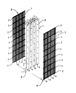
Fig. 2 is an exploded perspective of the said panel showing the two outer
steel
reinforcement components comprising of a wire mesh, longitudinal and
transverse
open web studs welded together and in the middle is the plastic form backing
with a
plurality of plastic connectors or can also be referred as the core.
8
CA 3150113 2022-02-28
Fig. 3 is a plan view of the transverse open web stud assembly.
Fig. 4 is a perspective view of the plastic connector.
Fig. 5 is a side view of the plastic connector showing the planar base and
clasp
design..
Fig. 6 is a side view of the longitudinal open web stud assembly.
Fig. 7 is a perspective of the plastic form backing with a plurality of
plastic
connectors on both sides.
Fig. 8 is a cross section of groove edge on the shorter side of the said
panel.
Fig.9 is a cross section of the tongue edge on the shorter side of panel.
Fig. 10 is an illustrated isometric view of a concrete column showing a
portion
of the panel as one example of its intended use.
Fig. 11 is an isometric view illustrating concrete foundation wall and footing
showing a portion of the new invention.
DETAILED DESCRIPTION OF THE INVENTION
The applicant had invented a novel dimensional multi-purpose panel
comprising of a wire mesh, a plurality of longitudinal and transverse open web
studs
welded together to form a steel reinforcement assembly as first component, a
plastic
form backing with ribs or corrugation with a plurality of plastic connectors
attached
on both sides as a second component and can also be referred as the core, and
another
wire mesh with a plurality of longitudinal and transverse open web studs
welded
together in a manner to form the steel reinforcement assembly as the third
component.
All three components form the new invention.
Figs.1 to 9 will show all the components and its corresponding elements that
form the new invention.
9
CA 3150113 2022-02-28
Referring now to the drawings, Fig. 1 shows the perspective view of the new
invention referred to as dimensional multi-purpose panel 1 comprising of a
steel
reinforcement assembly 2 as first component, a plastic assembly 3 as the
second
component and can also be referred to as the core, and steel reinforcement
assembly 4
as the third component.
Fig. 2 is an exploded view of the multi-purpose panel showing the steel
reinforcement assembly which is the first component 2; comprising of a
plurality of
transverse open web studs 5 placed at an equidistant to each other, a
plurality of
longitudinal open web studs 6 placed on center of the ribs of plastic form and
wire
mesh 7 of equal dimensions of the second component 3, comprising of a plastic
form
backing 8 and plurality of plastic connectors 9 on both sides, and component 4
which
comprises also of longitudinal open web stud 6 and transverse open web stud 5
and
wire mesh 7. Wire mesh can be obtained from steel reinforcing bars and wire
companies.
Fig. 3 shows the top view of a transverse open web stud 5, comprising of two
plain steel wire 5a of equal diameter of the wire mesh and a plain wire bended
45
degrees in contiguous manner forming a zigzag wire 5b.
To form the transverse open web stud 5 is by welding plain steel wire 5a in
contact with the outer bent side of the zigzag wire 5b and another plain steel
wire 5a
on the opposite side of the zigzag wire 5b. This assembly serves as the
horizontal
reinforcement of the novel invention. Manufacturing steps include the bending
of
steel wire to form a zigzag wire 5b and welding plain steel wire5a which is in
contact
with the outer bent part on one side and on the opposite of the zigzag wire
5b.
Fig. 4 is a perspective view of the plastic connector 9 where 9a is referred
to
as clasp of the connector with the inside diameter corresponding to the
outside
diameter of the plain steel wire 6a, as shown on Fig. 6. Manufacturing steps
includes
forming the plastic connector 9 using recycled plastic such as High Density
Polyethylene (HDPE). A mold may be used to form the plastic connector.
CA 3150113 2022-02-28
Fig. 5 is a side view of the plastic connector 9 showing the base 9b which has
a minimal thickness as a spacer which holds steel reinforcement in its proper
position
at which it also holds wall forms at a given distance apart before and during
concreting, and a clasp 9a with an inside diameter corresponding to the
outside
diameter of the plain steel wire 6a as shown in Fig. 6 for easy attachment of
the
longitudinal open web stud 6.
Fig. 6 is a side view of the longitudinal open web stud 6 comprising of two
plain steel wire 6a and zigzag plain steel wire 6b bent at 45 degree angle in
a
continuous manner. To form the longitudinal open web stud component is by
welding
one plain steel wire 6a to the zigzag wire 6b on both sides in the same manner
as to
the transverse open web stud 5. This steel reinforcement assembly, serves as
the
vertical reinforcement of the new invention.
Fig. 7 is an isometric view of the second component 3 also referred as the
core
of the new invention comprising of the plastic form backing 8 and a plurality
of
plastic connector 9. This plastic connector 9 can be attaching to the plastic
form
backing 8 by glue using high strength bonding solution.
The plastic form backing 8 with a nominal thickness maybe 1/4" is shape with
ribs12 and 14 oriented parallel to its longer side, respectively so that a
recess 13
forms the depth of the rib 12 and 14 in a continuous manner. Insulating
materials can
be inserted into ribs 12 and 14, respectively.
The numerous advantages of the plastic form backing 8 include permanent
form for the concrete mix, serves as sheathing materials and as an air and
vapor
barrier. The plastic connector 9 attaching to the plastic form backing 8 is
design to
hold and secure tightly the steel reinforcement components and it also acts as
a
thermal break from steel reinforcement thermal conductivity. Manufacturing
steps of
the plastic form backing 8 using recycled high-density polyethylene (HDPE) can
be
done by thick gauge thermoforming process. The plastic form backing with its
specified shape and characteristics can be obtained from thermoforming
companies.
11
CA 3150113 2022-02-28
Fig. 8 is a cross section of the edge of the shorter side of the plastic form
backing 8 showing a groove 9 with a nominal radius 9a of may be 3/16"which is
continuously along the length on side of the said panel and depth 9b of maybe
1/4".
Likewise, Fig. 9 is a cross section of the edge on the opposite side of the
plastic form backing 8 showing the tongue 10 with a nominal radius 10a of
maybe
3/16" and a depth 10b of maybe 1/4", which also runs along the length on the
opposite side of the new invention.
The tongue 10 and groove 9 design of the longer sides of the plastic form
backing 8 can be made of the same thickness in order that it can be snap to
another
panel tightly; i.e. in wall construction particularly and can be applied with
sealant to
be air tight.
To fabricate the new invention the steps are as follows:
(a) Assemble the first component 2 and third component 4 as shown in Fig. 2
and
Fig. 3 shows how to form the zigzag wire 5b is by bending a plain steel wire
5a at an angle of 45 degrees with a diagonal length of may be 2-1/2" in a
contiguous manner. To assemble the transverse open web stud 5 is by welding
a plain steel wire 5a to the outer bent edges of the zigzag wire 5b and
another
plain steel wire 5a on the opposite side of zigzag wire 5b.
(b) Assemble longitudinal open web stud as shown in Fig. 6 by bending a
plain
steel wire 6a at an angle of 45 degrees with a diagonal length of may be 2-
1/2" in a continuous manner forming a zigzag wire 6b. To assemble the
longitudinal open web stud 6 is by welding plain steel wire 6a to the outer
bent edges of the zigzag wire 6b and another plain steel wire 6a on the
opposite edges of the zigzag wire 6b. The number of longitudinal open web
stud 6 should correspond to the number of ribs 12 and 14, respectively as
shown in Fig. 2 on both sides of the plastic form backing 8.
12
CA 3150113 2022-02-28
(e) The reinforcement assembly 2 and 4 can be attached to the
plastic assembly
by snapping the plain steel wire 6a (Fig. 6) of the longitudinal open web stud
6 as shown in Fig. 2 to the clasp 9a (Fig. 5) of the plastic connector 9 (Fig.
4).
(0 The final assembly of the three components completes the new
invention.
EXAMPLES OF INTENDED USE OF THE INVENTION
An important advantage of the novel invention is its versatility as a building
material as it can be utilized as a permanent formwork, as a framework for
natural
degradation and to mitigate the effect of blast on columns and piers
particularly. This
can be understood in the drawing Fig. 10 that is an illustrated isometric view
of a
concrete column C showing a portion of the panel 1, and reinforcing bars R
with
stirrups S.
In constructing a reinforced concrete column, the vertical reinforcing bars
are
attached either by welding or tie wire to the foundation reinforcement after
which the
concrete mix will be poured into the footing or foundation, the stirrups or
hoops will
be installed and secured by welding or tie wire around the perimeter of the
reinforcing
bars after which the formwork is erected and secured properly so pouring of
concrete
for the column will be applied.
The same method is applied in construction of columns utilizing the new
invention as a permanent formwork. Referring to Fig. 10, once panels 1 are
erected,
all corner joints are measured, cut and glued i.e. the plastic form backing
joints, and
all reinforcement assemblies are tied or spot weld, installation of all
necessary
insulation including may be blast proofing materials in the ribs 12 and 14
(Fig.2) of
the new invention can be done after which concrete mix can be sprayed on the
outer
side of panel 1 to a desired thickness.
14
CA 3150113 2022-02-28
The transverse open web stud assembly 5 can be cut and oriented
perpendicular to the longitudinal open web stud assembly 6 in order that plain
steel wire 5a can be aligned and in contact with plain steel wire 6a of both
transverse and longitudinal open web studs 5 and 6, respectively and can be
joined by welding, as shown in Fig. 2. This process is applied in all
transverse
and longitudinal open web studs 5 and 6 welding connections except on both
ends of the longitudinal open web studs 6. A continuous length of transverse
open web studs 5 can be place and oriented perpendicularly to abut to one end
of the longitudinal open web stud 6 and another continuous transverse open
web stud 5 on the opposite end and all joints can be welded together.
(c) Once all transverse and longitudinal open web studs 5 and 6,
respectively are
cut in detail to correspond to the dimension of the plastic assembly 3 i.e.
length of transverse open web stud 5 will correspond to the width of the
plastic assembly 3 and interconnected by welding. To complete the
reinforcement component is by welding the wire mesh of equal dimension of
the plastic form backing 8 as shown in Fig. 2 to all the joints of the
transverse
and longitudinal open web studs 5 and 6 assembly, respectively.
(d) The plastic component as shown in Fig. 2 comprising of plastic form
backing
8 and plastic connector 9 can be obtained from thermoforming companies
who can manufacture and pre assemble said plastic components based on
specification and technical description provided. Another process is obtaining
the plastic form backing 8 and plastic connectors 9 from thermoforming
companies and assemble the two elements by gluing using high strength
bonding solution. Placement of the plastic connector 9 can be oriented in a
manner so that the base 9b (Fig. 5) is co-planar to the surface of the ribs 12
and 14 (Fig. 2) and the center of the clasp 9a will coincide with the center
of
the ribs 12 and 14
13
CA 3150113 2022-02-28
A curing time for the freshly applied concrete on the outer side of panel 1
may
be 1 or 2 days before the final pouring of concrete mixture for the column can
be
done. This is one important advantage of the new invention, which also serves
as an
encasement or concrete confinement particularly in columns exposed to weather
condition and above ground independent columns or piers.
Utilizing as a framework for concrete foundation wall particularly in
residential basement construction is another important advantage of the new
invention. Foundation basics include all foundation wall types need to sit on
a footing
that sits below the frost grade.
One type is the poured concrete foundation wall constructed by erecting
forms on top of the footings, after which concrete mix is poured into. Once
the
concrete foundation walls have partially cured the forms are removed. After it
has
reached curing time the foundation is ready to be backfilled. But prior to
backfilling
of the exterior side of the foundation wall, the basement floor slab
preferably should
be poured with concrete, which adds backpressure to the foundation wall and
footing.
The method of using the new invention as framework for poured in place
concrete for foundation wall and floor slab includes erecting the panels once
the
footings are set. Dowel reinforcement should be placed perpendicular to the
reinforcement of the footing and can be tied using tie wires before the
spraying of the
concrete mix is done. Dowel reinforcement means a steel rod or reinforcing bar
embedded across the joint where two pieces of concrete join to strengthen and
to
prevent cracking.
The panel can be inserted on the dowel reinforcement and aligned with the
footing to desired specification. The dowel reinforcement can be joined and
tied with
a tie wire to the reinforcement assembly of the panel.
CA 3150113 2022-02-28
This could be best understood in Fig. 11, which is an isometric view
illustrating a concrete foundation wall and footing joint showing a portion of
the
panel 1.
The concrete wall W is joined with the footing F where the reinforcing bars R
of the footing being laid horizontally and dowel reinforcement D oriented
vertically
can be tied using tie wires to the reinforcement assembly of the panel 1.
Application
method of concrete mix can be done by pneumatic machine or manually. The
insulating materials I can be inserted into the ribs of panel 1 prior to the
spraying of
concrete mix. Any conduit pipes for electrical and heating coils can be
embedded and
tied to the reinforcement assembly of the new invention before the final
pouring or
spraying of concrete mix.
CLAIMS
1. A dimensional multi-purpose panel for use in the concrete
construction
comprising of;
(a) a steel reinforcement assembly as first component that includes a wire
mesh, a plurality of longitudinal and transverse open web stud that are formed
by
welding connection.
(b) a plastic assembly as second component and can also be referred as the
core which is form by a plastic form backing with ribs and a plurality of
plastic
connectors attaching on both sides of the said plastic form backing by gluing
using
high strength bonding solution.
(c) another steel reinforcement assembly as the third component that
includes a wire mesh, a plurality of longitudinal and transverse open web
studs that
are formed by welding connection.
16
CA 3150113 2022-02-28
2. A dimensional multi-purpose panel as defined in Claim 1 wherein the
first
component comprising of a plurality of longitudinal open web studs that are
formed
by welding a plain wire that is in contact to the outer bent edges of the
zigzag wire
which is bent to an angle of 45 degrees in a continuous manner that are in
contact and
another plain wire welded to the opposite side on the outer bent edges of the
zigzag
wire.
3. A dimensional multi-purpose panel as defined in Claim 2 wherein the
length
of the longitudinal open web stud is two plain wire diameter less than the
length of
the of the wire mesh.
4. A dimensional multi-purpose panel as defined in Claim 3 wherein the
longitudinal open web studs is placed at specific distance apart from each
other.
5. A dimensional multi-purpose panel as defined in Claim 1 wherein the
first
component comprising of a plurality of transverse open web studs that are
formed by
welding a plain wire welded to the outer bent edges of the zigzag wire bent at
an
angle of 45 degrees in a continuous manner that are in contact and another
plain wire
welded to the opposite side on the outer bent portion of the zigzag wire.
6. A dimensional multi-purpose panel as defined in Claim 5 wherein the
width of
the transverse open web stud is equivalent to the width of the plastic form
backing.
7. A dimensional multi-purpose panel as defined in Claim 6 wherein a
plurality
of transverse open web studs are cut and placed perpendicularly at
equidistance so
that the ends abut to the longitudinal open web stud and are connected by
welding.
8. A dimensional multi-purpose panel as defined in Claim 7 wherein two
continuous transverse open web stud, which are cut equal to the width of the
plastic
form backing are placed and abutted on both ends of the longitudinal open web
studs
and all joints are welded.
17
CA 3150113 2022-02-28
9. A dimensional multi-purpose panel as defined in Claim 1 wherein the
length
and width of the wire mesh is equivalent to the length and width of the
plastic form
backing.
10. A dimensional multi-purpose panel as defined in Claim 9 wherein the
wire
mesh is connected to the longitudinal and transverse open web studs assembly
to
form the first component.
11. A dimensional multi-purpose panel as defined in Claim 1 further
comprising
of a plastic form backing with edges forming ribs oriented parallel to the
longer side
of the said plastic form backing.
12. A dimensional multi-purpose panel as defined in Claim llwherein the
edges
forming ribs of the plastic form backing have recesses with a minimal depth in
order
for insulating materials can be inserted therein.
13. A dimensional multi-purpose panel as defined in Claim 12 wherein the
plastic
form backing has groove with a minimal radius equal to the radius of the
tongue on
the opposite side of the said plastic form backing.
14. A dimensional multi-purpose panel as defined in Claim 1 wherein the
plastic
connector is formed with a clasp on one end with an inner radius equal to the
outer
radius of the longitudinal open web stud and a planar base on the other end.
15. A dimensional multi-purpose panel as defined in Claim 14 wherein the
planar
base of the plastic connector has a minimal thickness, which serves as a
spacer means
to hold steel reinforcement in its proper position at which also holds wall
forms at a
given distance apart before and during concreting.
16. A dimensional multi-purpose panel as defined in Claim 15 wherein the
plastic
connectors are attached on both sides of the plastic form backing by glue
using high
strength bonding solution, which form the second component.
18
CA 3150113 2022-02-28
17. A dimensional multi-purpose panel as defined in Claim 10 comprising of the
first
component wherein the longitudinal open web studs are attached to second
component by snapping to the clasp end of the plastic connectors.
18. A dimensional multi-purpose panel as defined in Claim 1 further
comprising
of another steel reinforcement assembly with a plurality of longitudinal open
web
studs that are formed by welding one plain wire on both sides which are in
contact
with the outer bent portion of a zigzag wire bent at an angle of 45 degrees in
a
contiguous manner.
19. A dimensional multi-purpose panel as defined in Claim 18 wherein the
longitudinal open web studs is placed at specific distance apart and a
plurality of
transverse open web studs are cut and placed perpendicularly at equidistance
so that
the ends abut to the longitudinal open web stud and are welded.
20. A dimensional multi-purpose panel as defined in Claim 19 wherein the
length
of the longitudinal open web studs are two wire diameters less than the length
of the
plastic form backing.
21. A dimensional multi-purpose panel as defined in Claim 1 further
comprising
of another steel reinforcement assembly with a plurality of transverse open
web studs
that are formed by welding one plain wire on both sides which are in contact
with the
outer bent portion of a zigzag wire bent at an angle of 45 in a contiguous
manner.
22. A dimensional multi-purpose panels as defined in Claim 21 wherein two
continuous transverse open web stud, which are cut equal to the width of the
plastic
form backing are placed and abutted on both ends of the longitudinal open web
studs
and all joints are welded.
23. A dimensional multi-purpose panel as defined in Claim 23 where in the
width
of the transverse open width studs are equal to the width of the plastic form
backing.
19
CA 3150113 2022-02-28
24. A dimensional multi-purpose panel as defined in Claim 1 further
comprising
of another mesh wire with length and width equal to the plastic form backing.
25. A dimensional multi-purpose panel as defined in Claim 24 wherein the
wire
mesh is connected to the longitudinal and transverse open web studs assembly
to
form the third component.
26. A dimensional multi-purpose panel as defined in Claim 17 wherein the
first
component is attached to the second component.
27. A dimensional multi-purpose panel as defined in Claim 26 wherein the
final
assembly of the new invention can be completed by attaching the third
component.
* * * *
CA 3150113 2022-02-28