Note: Descriptions are shown in the official language in which they were submitted.
Attorney Docket No. 2861-14
VEGETATION HANGING AND DRYING SYSTEM
CROSS-REFERENCE TO RELATED APPLICATIONS
[0001] This application claims the benefit of and priority to U.S.
Provisional Patent
Application Nos. 63/155,851 and 63/155,849 each filed on March 3, 2021, the
entire contents of
each of which being incorporated by reference herein.
BACKGROUND
[0002] Recently there has been a widespread growth of the use of cannabis
and hemp ranging
from medicinal to recreational. In this widespread growth, the drying of
cannabis and hemp has
become an essential part of the processing of cannabis and hemp, but the
process takes a significant
amount of time and effort. Typically, the drying process requires the hemp
and/or cannabis to be
hung with plastic netting, which is not only time-consuming but requires a lot
of manual labor and
leaves little room for error.
[0003] The plastic netting process requires the hemp and/or cannabis to be
hung one branch at
time and threaded through the netting to secure the hemp and/or cannabis.
Removal of the hemp
and/or cannabis requires careful unthreading of the hemp and/or cannabis from
the plastic netting.
Additionally, from harvest to drying there is multiple contacts with the hemp
and/or cannabis that
diminishes the quality of the finished dried product. Therefore, there is a
need to provide a system
of hanging and drying vegetation, such as, hemp, cannabis, and other plants
harvested and
subsequently dried, without damaging the vegetation.
SUMMARY
[0004] In one aspect, the present disclosure provides a multi-rack bracket
for use in a
vegetation hanging and drying system. The multi-rack bracket includes a main
plate, first and
second side plates, and first and second flanges. The main plate has a
generally triangular shape
1
Date Recue/Date Received 2022-03-01
Attorney Docket No. 2861-14
and includes a first lateral edge and an opposite second lateral edge. The
first side plate extends
perpendicularly from the first lateral edge of the main plate, and the second
side plate extends
perpendicularly from the second lateral edge of the main plate. The first
flange extends upwardly
from the first side plate, and the second flange extends upwardly from the
second side plate. The
first and second flanges define a gap therebetween configured for capturing a
vertical support shaft
of the vegetation hanging and drying system. The main plate, the first side
plate, and the second
side plate collectively define a cavity configured for receipt of a leg
assembly and the vertical
support shaft of the vegetation hanging and drying system.
[0005] In aspects, the main plate may include a bottom portion having the
first and second
lateral edges, and a top portion extending upwardly from the bottom portion.
The top portion may
extend alongside of the first and second flanges.
[0006] In aspects, the top portion of the main plate and the first and
second flanges may
collectively define a rectangular-shaped channel configured to capture the
vertical support shaft
therein.
[0007] In aspects, each of the first and second flanges may have a tab
extending downwardly
therefrom and into the cavity to resist tilting of the vertical support shaft
relative to the first and
second flanges.
[0008] In aspects, the tabs may be coplanar with the respective first and
second flanges.
[0009] In aspects, each of the main plate, the first and second side
plates, and the first and
second flanges may have one or more holes configured for receipt of a
fastener.
[0010] In aspects, the first side plate may be parallel with the first
lateral edge of the main
plate, and the second side plate may be parallel with the second lateral edge
of the main plate.
[0011] In aspects, the first and second flanges may be parallel with one
another.
2
Date Recue/Date Received 2022-03-01
Attorney Docket No. 2861-14
[0012] In aspects, the main plate, the first and second side plates, and
the first and second
flanges may be monolithically formed with one another from a single piece of
sheet metal.
[0013] In aspects, the first and second flanges may extend at an obtuse
angle from the
respective first and second side plates.
[0014] In accordance with another aspect of the present disclosure, a
vegetation hanging and
drying system is provided that includes a harvest stand, a first multi-rack
bracket, and a second
multi-rack bracket. The harvest stand includes first and second leg
assemblies, a horizontal shaft
configured to extend between and interconnect the first and second leg
assemblies, and first and
second vertical support shafts configured to extend upwardly from the
respective first and second
leg assemblies. The first multi-rack bracket is configured to secure the first
leg assembly to the
first vertical support shaft, and the second multi-rack bracket is configured
to secure the second
leg assembly to the second vertical support shaft. The first multi-rack
bracket includes a main
plate including a first lateral edge and an opposite second lateral edge, a
first side plate extending
perpendicularly from the first lateral edge of the main plate, a second side
plate extending
perpendicularly from the second lateral edge of the main plate, a first flange
extending upwardly
from the first side plate, and a second flange extending upwardly from the
second side plate. The
first and second flanges define a gap therebetween configured for capturing
the first vertical
support shaft. The main plate, the first side plate, and the second side plate
collectively define a
generally triangular-shaped cavity configured for receipt of the first leg
assembly and the first
vertical support shaft.
[0015] In aspects, the main plate may have a generally triangular shape.
[0016] In aspects, the vegetation hanging and drying system may further
include a pair of
hanging bar brackets configured to attach to top ends of the respective first
and second vertical
3
Date Recue/Date Received 2022-03-01
Attorney Docket No. 2861-14
support shafts. Each of the pair of hanging bar brackets may include a main
plate, and a pair of
spaced-apart fingers extending upwardly from the main plate. The main plate of
the hanging bar
brackets defines one or more holes configured for receipt of a fastener. The
main plate of the
hanging bar brackets may be configured to abut the top end of the respective
first and second
vertical support shafts.
[0017] In aspects, the vegetation hanging and drying system may further
include a horizontal
support bar for supporting a plurality of hangers thereon. The pair of fingers
of each of the hanging
bar brackets may define a rectangular-shaped notch configured for receipt of
an end portion of the
horizontal support bar.
[0018] In aspects, the first leg assembly may include a pair of elongate
elements configured to
abut against the respective first and second side plates and the main plate of
the first multi-rack
bracket. The first vertical support shaft may be configured to be positioned
and captured between
the pair of elongate elements.
[0019] In accordance with aspects of the present disclosure, a hanging bar
bracket for coupling
to a vegetation and drying system is provided and includes a main plate
defining one or more holes
configured for receipt of a fastener, and a pair of spaced-apart fingers
extending upwardly from
the main plate. The pair of fingers define a rectangular-shaped notch
configured for receipt of a
horizontal support bar.
[0020] The details of the disclosure are set forth in the accompanying
drawings and the
description below. Other features, objects, and advantages of the techniques
described in this
disclosure will be apparent from the description and drawings, and from the
claims.
4
Date Recue/Date Received 2022-03-01
Attorney Docket No. 2861-14
[0021] As used herein, the terms parallel and perpendicular are understood
to include relative
configurations that are substantially parallel and substantially perpendicular
up to about + or ¨ 10
degrees from true parallel and true perpendicular.
BRIEF DESCRIPTION OF DRAWINGS
[0022] Aspects of the presently disclosed multi-rack bracket are described
in detail with
reference to the drawings, in which like reference numerals designate
identical or corresponding
elements in each of the several views.
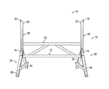
[0023] FIG. 1 is a front, perspective view illustrating a vegetation
hanging and drying system
including a stand assembled with a pair of multi-rack brackets, and a pair of
hanging bar brackets
attached to the stand;
[0024] FIG. 2 is a side, perspective view illustrating a leg assembly of
the stand and the multi-
rack bracket securing the leg assembly to a vertical support shaft of the
stand;
[0025] FIG. 3 is a plan view illustrating the multi-rack bracket of FIG. 2;
[0026] FIG. 4 is a plan view illustrating the hanging bar bracket of the
system of FIG. 1;
[0027] FIG. 5 is another aspect of a vegetation hanging and drying system
including the stand,
a horizontal support bar supported on the stand, and a vegetation hanger
supported on the
horizontal support bar; and
[0028] FIG. 6 is another aspect of a vegetation hanging and drying system
including a column
stand, a number of horizontal support bars supported on the stand, and a
plurality of vegetation
hangers supported on the horizontal support bars.
DETAILED DESCRIPTION
[0029] The present disclosure may be understood more readily by reference
to the following
detailed description of the disclosure taken in connection with the
accompanying drawing figures,
Date Recue/Date Received 2022-03-01
Attorney Docket No. 2861-14
which form a part of this disclosure. It is to be understood that this
disclosure is not limited to the
specific devices, methods, conditions or parameters described and/or shown
herein, and that the
terminology used herein is for the purpose of describing particular
embodiments by way of
example only and is not intended to be limiting of the claimed disclosure.
Also, as used in the
specification and including the appended claims, the singular forms "a," "an,"
and "the" include
the plural, and reference to a particular numerical value includes at least
that particular value,
unless the context clearly dictates otherwise. Ranges may be expressed herein
as from "about" or
"approximately" one particular value and/or to "about" or "approximately"
another particular
value. When such a range is expressed, another embodiment includes from the
one particular
value and/or to the other particular value. Similarly, when values are
expressed as approximations,
by use of the antecedent "about," it will be understood that the particular
value forms another
embodiment. It is also understood that all spatial references, such as, for
example, horizontal,
vertical, top, upper, lower, bottom, left and right, are for illustrative
purposes only and can be
varied within the scope of the disclosure. For example, the references "top"
and "bottom" are
relative and used only in the context to the other, and are not necessarily
"superior" and "inferior."
[0030]
With reference to FIG. 1, the present disclosure is directed to a vegetation
hanging and
drying system 10 for suspending vegetation, and most suitably cannabis, to
allow the vegetation
to dry after harvesting. The vegetation hanging and drying system 10 generally
includes a stand
12, a pair of multi-rack brackets 14, 16 for assembling the components of the
stand 12 together,
and a pair of hanging bar brackets 18, 20 secured to opposite lateral sides of
the stand 12 and
configured to support a horizontal support bar 120 (FIG. 5), which allows for
the hanging of
vegetation hangers 140 (FIG. 5) thereon. The vegetation hangers 140 support
the vegetation (e.g.,
cannabis) thereon to allow the vegetation to dry prior to harvesting.
6
Date Recue/Date Received 2022-03-01
Attorney Docket No. 2861-14
[0031] The stand 12 of the vegetation hanging and drying system 10 includes
first and second
leg assemblies 22, 24, first and second vertical support shafts 26, 28
extending upwardly from
respective first and second leg assemblies 22, 24, and first and second
horizontal support shafts
30, 32 that couple, in a spaced-apart state, the first and second leg
assemblies 22, 24 to one another.
It is contemplated that the stand 12 may be provided as a kit where the end
user assemblies the
various components to one another to build the stand 12. In other aspects, the
stand 12 may be
provided to the consumer preassembled.
[0032] Each of the first and second leg assemblies 22, 24 of the stand 12
includes first and
second elongate elements 34, 36 and 38, 40 (e.g., dimensional lumber)
configured to be angled
relative to one another (e.g., from about 45 to about 90 degrees). The first
vertical support shaft
26 is configured to be captured between top ends of the first and second
elongate elements 34, 36
of the first leg assembly 22, and the second vertical support shaft 28 is
configured to be captured
between top ends of the first and second elongate elements 38, 40 of the
second leg assembly 24.
The first and second elongate elements 34, 36 of the first leg assembly 22 are
configured to be
fixed relative to one another and to the first vertical support shaft 26 using
the first multi-rack
bracket 14, and the first and second elongate elements 38, 40 of the second
leg assembly 24 are
configured to be fixed relative to one another and to the second vertical
support shaft 28 using the
second multi-rack bracket 16, as will be described in further detail below.
Since the multi-rack
brackets 14, 16 are identical or substantially similar, only the first multi-
rack bracket 14 will be
described in detail.
[0033] With reference to FIGS. 2 and 3, the multi-rack bracket 14 includes
a main plate 42,
first and second side plates 44, 46, and first and second flanges 48, 50. The
main plate 42, the first
and second side plates 44,46, and the first and second flanges 48, 50 may be
monolithically formed
7
Date Recue/Date Received 2022-03-01
Attorney Docket No. 2861-14
with one another from a single piece of sheet metal and bent relative to one
another to form the
bracket 14 as shown. The main plate 42, the first side plate 44, and the
second side plate 46
collectively define a cavity 52, such as a triangular-shaped cavity,
configured for receipt of the first
leg assembly 22 and the vertical support shaft 26 of the stand 12.
[0034] The main plate 42 includes a bottom portion 42a having a trapezoidal
shape, and a top
portion 42b extending upwardly from the bottom portion 42a. The main plate 42
may have a
generally triangular shape. The bottom portion 42a has a first lateral edge 54
and an opposite
second lateral edge 56. The first side plate 44 may have a rectangular shape
and extend
perpendicularly from the first lateral edge 54 of the bottom portion 42a of
the main plate 42, and
the second side plate 46 may have a rectangular shape and extend
perpendicularly from the second
lateral edge 56 of the bottom portion 42b of the main plate 42.
[0035] More specifically, the first side plate 44 has a bottom portion 44a
that is bent relative
to or about the first lateral edge 54 of the main plate 42 at a perpendicular
angle, and the second
side plate 46 has a bottom portion 46a that is bent relative to or about the
second lateral edge 56
of the main plate 42 at a perpendicular angle. As such, the bottom portion 44a
of the first side
plate 44 extends parallel with and along the first lateral edge 54 of the main
plate 42, and the
bottom portion 46a of the second side plate 46 extends parallel with and along
the second lateral
edge 56 of the main plate 42. In aspects, the first and second side plates 44,
46 may be coupled to
the respective first and second lateral edges 54, 56 of the main plate 42 via
any suitable fastening
means, such as, for example, welding, adhesive, soldering, or the like.
[0036] The first side plate 44 further includes a top portion 44b that is
spaced from the top
portion 42b of main plate 42, and the second side plate 46 has a top portion
46b that is spaced from
8
Date Recue/Date Received 2022-03-01
Attorney Docket No. 2861-14
the top portion 42b of the main plate 42 to allow for flexing of the upper
portion of the multi-rack
bracket 14 to facilitate accommodating the components of the first leg
assembly 22 therein.
[0037] The first flange 48 of the multi-rack bracket 14 extends upwardly at
an obtuse angle
(e.g., from about 100 degrees to about 165 degrees) from the top portion 44b
of the first side plate
44. The second flange 50 of the multi-rack bracket 14 extends upwardly at an
obtuse angle from
the top portion 46b of the second side plate 46. The first and second flanges
48, 50 face one
another, extend parallel with one another, and are spaced-apart to define a
gap therebetween
configured for capturing the first vertical shaft 26 of the vegetation hanging
and drying system 10.
The first and second flanges 48, 50 define a plane extending perpendicularly
to a plane defined by
the top portion 42b of the main plate 42 such that the first and second
flanges 48, 50 and the top
portion 42b of the main plate 42 collectively define a rectangular-shaped
channel 58 configured to
capture the first vertical support shaft 26.
[0038] Each of the first and second flanges 48, 50 has a tab 60, 62
extending downwardly
therefrom and into the cavity 52 to resist tilting of the vertical support
shaft 22 relative to the first
and second flanges 48, 50. The tabs 60, 62 are coplanar with the respective
first and second flanges
48, 50. The tabs 60, 62 may be formed by making rectangular cutouts in the top
portions 44b, 46b
of the first and second side plates 44, 46 and bending the first and second
flanges 48, 50 relative
to the top portions 44b, 46b of the first and second side plates 44, 46.
[0039] Each of the main plate 42, the first and second side plates 44, 46,
and the first and
second flanges 48, 50 has a plurality of holes 64 defined therethrough
configured for receipt of a
metal fastener, such as, for example, a screw. In aspects, the multi-rack
bracket 14 may be
fabricated from a lightweight metal, plastic, composite material, or any other
suitable material.
9
Date Recue/Date Received 2022-03-01
Attorney Docket No. 2861-14
[0040] With reference to FIGS. 1 and 4, the hanging bar brackets 18, 20 may
form a part of
the vegetation hanging and drying system 10. The hanging bar brackets 18, 20
each include a main
plate 70, and a pair of spaced-apart fingers 72, 74 extending upwardly from
the main plate 70 and
being coplanar therewith. The main plate 70 may have a rectangular shape and
define a pair of
upper and lower holes 76, 78 configured for receipt of a fastener. The pair of
spaced-apart fingers
72, 74 each have a bottom end formed with or otherwise coupled to the main
plate 70, and a top
end 80, 82. The top end 80, 82 of the fingers 72, 74 may be tapered to
facilitate insertion of a
horizontal support bar 120 (FIG. 5) therebetween. The fingers 72, 74 define a
rectangular-shaped
notch 84 configured for receipt of the horizontal support bar 120 (FIG. 5).
The rectangular shape
of the notch 84 corresponds with a rectangular-shaped cross-section of the
horizontal support bar
120 and resists rotation of the horizontal support bar 120 within and relative
to the hanging bar
brackets 18, 20. The hanging bar brackets 18, 20 may be fabricated from a
lightweight metal,
plastic, composite material, or any other suitable material.
[0041] To assemble the hanging and drying system 10 of FIG. 1, top end
portions of the first
and second elongate elements 34, 36 of the first leg assembly 22 are
positioned into the cavity 52
(FIG. 3) of the first multi-rack bracket 14 and into abutment with the first
side plate 44 and an
inner surface of the main plate 42, and the second side plate 57 and the inner
surface of the main
plate 42, respectively. The first vertical shaft 26 is positioned between the
top end portions of the
first and second elongate elements 34, 36 and in the channel 58 of the multi-
rack bracket 14,
whereby the first leg assembly 22 is formed, as shown in FIGS. 1 and 2. While
holding the first
leg assembly 22, the first vertical support shaft 26, and the multi-rack
bracket 14 in place, the
fasteners 66 are positioned within the holes 64 of the multi-rack bracket 14
to secure the first side
plate 44 and the main plate 42 to the first elongate element 34, the first
flange 48 to the first vertical
Date Recue/Date Received 2022-03-01
Attorney Docket No. 2861-14
support shaft 26, the bottom and top portions 42a, 42b of the main plate 42 to
the first vertical
support shaft 26, the second side plate 46 and the main plate 42 to the second
elongate element 36,
and the second flange 50 to the first vertical support shaft 26. The second
leg assembly 24 and the
second vertical shaft 28 are assembled to one another using the second multi-
rack bracket 16 in
the same manner.
[0042] With the first and second leg assemblies 22, 24 secured to the
respective first and
second vertical shafts 26, 28, the first and second horizontal shafts 30, 32
are positioned between
and fastened to the first and second vertical shafts 26, 28. The main plate 70
(FIG. 4) of the
hanging bar brackets 18, 20 are fastened to top end portions 27, 29 of the
first and second vertical
shafts 26, 28, respectively. The notch 84 (FIG. 4) of the hanging bar brackets
18, 20 are positioned
above and in overlapping alignment with the top end portion 27, 29 of the
first and second vertical
shafts 26, 28. Opposing ends portions 120a, 120b (FIG. 5) of the horizontal
hanging bar 120 are
received within the notches 84 of the respective hanging bar brackets 18, 20
to position the
horizontal hanging bar 120 directly above the first and second vertical shafts
26, 28. The horizontal
hanging bar 120 may further include vegetation hangers 140 (FIG. 5) configured
to receive cut
vegetation.
[0043] With reference to FIG. 5, another type of a vegetation hanging and
drying system 100
is shown. The vegetation hanging and drying system 100 is similar to and may
include any of the
features of the vegetation hanging and drying system 10 of FIG. 1 except as
explicitly contradicted
below. The vegetation hanging and drying system 100 includes the stand 12, the
pair of multi-
rack brackets 14, 16, the horizontal support bar 120, and a pro hanger 140.
Instead of using the
hanging bar brackets 18, 20 of FIG. 4, the vegetation hanging and drying
system 100 of FIG. 5
11
Date Recue/Date Received 2022-03-01
Attorney Docket No. 2861-14
includes J-brackets 118 that attach to the top end portions 27, 29 of the
first and second vertical
shafts 28, 30.
[0044] Each of the J-brackets 118 has a hooked portion 122 configured to
protrude laterally
outward from the vertical shafts 26, 28 and defines a notch configured for
receipt of the respective
end portions 120a, 120b of the horizontal support bar 120. In this way, the
horizontal hanging bar
120 is offset from (e.g., to the side of) the first and second vertical
support shafts 26, 28.
[0045] The pro hanger 140 defines a rectangular-shaped hole in a middle
portion 144 thereof
that receives the horizontal support bar 120 to allow for sliding of the pro
hanger 140 therealong.
The pro hanger 140 further includes first and second elongated plates 146, 148
or blade portions
extending outwardly in opposing directions from the middle portion 144. The
first and second
elongated plates 146, 148 have an upper surface 150 defining a plurality of
undulations that support
and resist sliding of vegetation therealong.
[0046] FIG. 6 shows a similar hanging and drying system 200 as that shown
in FIG. 5, but has
first and second vertical shafts 202, 204 that extend at a height allowing for
the stacking of a
plurality of horizontal hanging bars 120.
[0047] Persons skilled in the art will understand that the devices
specifically described herein
and illustrated in the accompanying drawings are non-limiting exemplary
embodiments. It is
envisioned that the elements and features illustrated or described in
connection with one exemplary
embodiment may be combined with the elements and features of another without
departing from
the scope of the disclosure. As well, one skilled in the art will appreciate
further features and
advantages of the disclosure based on the above-described embodiments.
Accordingly, the
disclosure is not to be limited by what has been particularly shown and
described.
12
Date Recue/Date Received 2022-03-01