Note: Descriptions are shown in the official language in which they were submitted.
CA 03150571 2022-02-09
WO 2021/059007
PCT/IB2019/058231
1
Title: A track arrangement, an automated storage and re-.
trieval system and an automated storage and re-
trieval method
Description
TECHNICAL FIELD
[1] The present
disclosure is directed to a track arrangement for self-
driven carriages in a storage rack arrangement for automatically stor-
ing and accessing objects, wherein the storage rock arrangement
comprises a plurality of storage sites being arranged in at least two
racks extending over k storage levels, wherein the storage sites are ac-
by harizontd aisle tracks on each storage level, wherein the
aisle tracks extend in an aisle direction along aisles between the racks,
wherein the track arrangement connects each storage site with at
least one interaction site for automatically processing stored objects
analor automatically issuing objects to be stored. The present disclo-
sure also discloses an automated storage and retrievalsystem and an
automated storage and retrieval method.
BACKGROUND
21 Track
arrangements for self-driven carriages are known in the prior
art. Such arrangements comprise storage levels, which can be con-
nected by a lift, A lift is comparably complex and limits the throughput of
the storage and retrieval system. A track arrangement with a lift typically
comprises a number of moving and thus constructively demanding parts.
CA 03150571 2022-02-09
WO 2021/059007
PCT/IB2019/058231
2
[3] US. 20.17M50803A1 discloses an alternative track arrangement. To
connect different storage levels with each other a belt conveyor instead
of a lift is suggested. The belt conveyor conveys objects along ramped
sections of the conveyor to interactiOn sites on a storage level, where the
objects can be picked op by carriages that move along horizontal aisle
tracks.
[4] The carriages are bound to Its storage leVel and cannot change
the Storage level, The object to be transported Changes the storage level
by means of the belt conveyor. The object to be transported needs to be
handed over at least when the object is put on the belt convey& to be
Moved from one storage level to another Storage.level, when the Object
is picked up by a carriage at the storage level where it is to be moved to,
and potentially when the object is handed aver from the Carriage to the
storage site. Handing over the object is time consuming, and The carriage
Or the belt conveyor could be idle, depending on the demand to move
an object on a certain storage level,
[51 A track arrangement With a lift and/Or a belt conveyor are limited
in their efficiency by idle phases of the carriages: the belt conveyor,
and/or the lift when handing over objects at the belt conveyor or the lift,
respectively. Thus, the carriages, the belt conveyor, and/or the lift are lim-
ited in their occupancy. The belt conveyor and the lift are constructively
demanding and the cost...-efficiency of such an arrangement can be irn-
proved. It is thus desirable to avoid the limitation of the complexity of a
lift
or a belt conveyor:
[6] EP 3 570 194 Al discloses a warehouse management system with
ramps instead of a lift A plurality of carriages can traverse the track ar;-
=gement on any of the storage levels. The carriages can change the
storage level of the rack arrangement by ramps Which connect adjacent
storage levels, The tracks and the romps are arranged so that each
CA 03150571 2022-02-09
WO 2021/059007
PCT/IB2019/058231
3
carriage can follow a putative best route between its current position
and, e.g., an object and/or a storage site. More than one carriage can
choose a route with a driving direction opposite to the driving of another
carriage. Therefore, carriages can potentially crash with each other. To
avoid such a crash, a cantage can recalculate and change its route. The
change of a route implies that the formerly chosen putative best route
has potentially not been optimal and that the carriage has chosen a
route which is longer than necessary, Due to the presence of a plurality of
carriages and potential online scheduling of routes by the self-driven car-
t doges, such a potential crash can hardly be determined in advance. Due
to the change of the route, the time-consumption to transport an object
can increase in a manner that is hardly to be predicted. This can reduce
the occupancy of the interaction site and the overall efficiency of the
storage system.
SUMMARY
jfl it is a problem of the present disclosure to transport objects
effi-
ciently in a storage rack arrangement far automatically storing and ac-
cessing objects, which is cost-effective and avoids limitations of ihe oc-
cupancy when transporting, storing and retrieving objects.
[8] The problem is solved by the technical features of the independ-
ent claims,
[9] According to a first aspect of The present disclosure, the track ar-
rangement comprises at least z track levels, wherein z k, an entry
point on the mth track level for each interaction site, wherein rn01õ.,,Z),
and an exit point on the nth track level for each interaction site, wherein
n E flõõ,Z). From the entry point, the interaction site con be reached by
a carriage via tracks of the track arrangement. From the exit point, the
interaction site can be left by a carriage via tracks of the track
CA 03150571 2022-02-09
WO 2021/059007
PCT/IB2019/058231
4
arrangement'. The nzm track levei is called "entry point level" and the /it"
track level is called the "exit point level". The entry point level is the
track level at which o track leads from the entry point to the interaction
site:, The exit pOint level is the track level at which a track leads from the
interaction site to the exit point. The track level, at which the interaction
site is arranged, is Called "interaction site level". All track levels, or at
least :a subset of them, may correspond to the k Storage levels of the
storm*: rack arrangement. However, in some embodiments, the track
arrangement May comprise auxiliary intermediate track levels in addi-
fion to the track levels that correspond to the storage levels.
[10] According to the first aspect of the present disclosure, the track
arrangement further comprises for each interaction site: z m first one--
way ramps directed downward towards the entry point, m second
5 one-way ramps directed upward towards the entry point, z --A third
one-way ramps directed upward away from the exit point, and n-
fourth one-way ramps directed downward away from the exit point.
Therein; a one-way ramp is a romped track. A first one-way ramp is a
romped one-way track that. extends from track level z downward to z--
1, from z -1 to z 2, õ and from z -2r1 + I to 2.! - nt, A second one-way
romp a romped one-way track that extends upward from track level
Ito 2, from 2 to 3, and from n3- tO:n, A third one-way ramp is a
romped one-way track that extends upward from track level n to +1.
from + I to n + 2, and from z 1 to z. A fourth one-wayy ramp is a
ramped one-way track that extends downward from track level n to n
from n n - 2, and from 2 to 1,
[I 1] The one-way romps ensure that a carriage can change track
levels effectively. A carriage on a track level con access any other
track level by choosing a path along one or more of the one-way
ramps which leads to the chosen storage le,vel. A carriage can
transport on object over one or more storage levels from the interaction
CA 03150571 2022-02-09
WO 2021/059007
PCT/IB2019/058231
site to a storage site, or from a storage Site to the interaction site by the
one-way ramps, Le. a potentially time-consuming handing over of ob-
jects can be dispensed With. The throughput of the track arrangement
is determined by the tracks and the carriages and is not limited by
5 other transportation Means., e,g, by a lift or a belt conveyor, and/or a
carriage that is idle when waiting for said other transportation meansõ
Thereby, the complexity and the construction of the track arrangement
is comparably simple and comprises only one or more carriages as
movable parts which makes the track arrangement cost-effective.
[121 The one-way ramps ensure that there is at least one first path, i.e.
a route that a carriage can take, between a storage level and the in-
teraction site so that an object can be moved from a storage site to
the interaction site and at least one second path between the inferac-
site and any storage level so that an object can be moved from
the interaction site to a storage site: This reduces the risk of a potential
crash and therefore of a recalculation and change of a route.
[13] Optionally, for each interaction site the entry point and the exit
point may be arranged at an identical track level, In this embodiment
the interaction site can be reached from the same track level from
where the interaction site can be left. This is particularly efficient, when
an object is to be stored at and/or picked up From: the Storage level at
which the interaction site is arranged. in this embodiment, the entry
point level and the exit point level are identical per interaction site to
improve the efficiency of the layout and construction of the track ar-
rangement. In an alternative embodiment, the entry Oat level con be
different from the interaction site levet, This can be particularly effective
to provide a path without the risk of a collision, e.a:When the track or-
rangement comprises exactly one route via one-way ramps between
the entry point and the interaction Site.
CA 03150571 2022-02-09
WO 2021/059007
PCT/IB2019/058231
6
[14) Optionally, one or more of the first one-way ramps, of the sec-
ond one-way romps, of the third one-way ramps, and/or of the fourth
one-way ramps may be arranged to connect adjacent track leVeIS
with each other. This embodiment provides a track arrangement that
alloWs a carriage to move direct y from One track level to an adjacent
track level, i.e. from a track level n e (1,...,21: to an upper track level n
E 11,õ 2.} and/or to a lower track level n E ,Z). This embodi-
ment comprses shortest possible paths between ad acent storage lev-
els,
[151 Orz./tiOnally, one or more of the first one-way ramps, of the sec-
and one-way ramps, of the third one-way ramps and/or of the fourth
one-Way ramps may be (*tonged to connect next-nearest track levels
with each Other and/or at least Iwo track levels with each other having
twO or More track levels between said connected at least two track
i.e, such a pne,way ramp extends over at least. three track levels
hut does not need to connect adjacent track levels. This embodiment
provides a track arrangement:that allows a carriage to move directiy
from one track level too track level with at least one track level in be-
tween, Le. from a track level n to an upper storage level
s E and/or -to a lower storage level -4= E {1,...,Z),s 2.Thk
embodiment can be particularly effective in providing a path to pre-
vent a potential collision of carriages which improves the efficiency of
transportation.
[14] Optionally, the first one-way ramps may comprise a first se-
quence of first ramps, the second one-way ramps may comprise 0 sec-
ond sequence of second ramps, the third one-way romps may corn-
prise a third sequence of third romps. and/or the fourth one-way ramps
may comprise a fourth sequence of fourth romps, Preferably, 0 se-
quence of romps may be a plurality of one-way ramps, wherein an exit
point of one one-way ramp is identical to or dose to an entry point of a
CA 03150571 2022-02-09
WO 2021/059007
PCT/IB2019/058231
7
subsequent one-way ramp. e., o cordage can move alOng the se-
quence of ramps while traversing said one-way ramps without travers-
ing longer tracks other than said one-way raMps..AdvantdaeoUsly.
each subsequent pair atone-way ramps Of a sequence of ramps is
connected with each other by One or lwo horizontal Connection points.
A sequence of ramps improves the efficiency of transporting an object
from one level to another level by pasSing one or more levels in bet-
ween.
lo [17] =Optionally, the track arrangement May comprise a plurality of in-
teraction sites to issue and/6r retrieve a plurality of objects preferably
with a plurality of carriages simultaneously. The interaction sites can be
arranged at an identical track level Alternatively, at least two interac-
tion sites can be arranged at different track. levels which can improve
the performance of the automated storage and retr Oval system, e.g.
when one interaction site is arranged near storage sites which are ac-
cessed more frequently than other storage sites further away from said
interaction site.
[18] Qptionolly, o first subset of first one-way romps, a second subset
of second one-way ramps, a third subset of third one-way camps,
and/or a fourth subset of fourth one-way ramps may be configured to
connect any one of the storage sites with exactly one interaction site.
The first subset of first one-way ramp$ may comprise preferably
z first one-way ramps directed downward towards the entry Om`
of the interaction that it connects to. It is possible That the track ar-
rangement comprises a plurality of first subsets of first one-way romps.
wherein any two first subsets of first one-way romps are configured to
connect to different interaction sites The second subset of second one-
way romps comprises preferably ==== I second one-way ramps directed
upward towards the entry point. The third subset of third one-way ramps
comprises preferably z n third one-way romps directed upward away
CA 03150571 2022-02-09
WO 2021/059007
PCT/IB2019/058231
8
from the exit point. The fourth subset of fourth One-way ramps comprises
preferably n-1. fourth one-way ramps directed downward away from
the exit point, Similarly, OS explained with reference to the first Subset Of
first one-way ramps, the track arrangement can comprise a .plurality of
second subsets of Second one-way trackS, third subsets of third one-
way tracks and/or fourth subsets of fourth one-way tracks wherein any
Iwo of said subsets of One-way ramps are configured to connect to dif-
ferent interaction sites. This is particular effective since the risk of colli-
sions of Carriages on The routes from an entry point and it interaction
site can be significantly reduced.
[19] Optionally, for each interaction site, the first subset of 'first one-
way ramps, the second subset of second one-way ramps, the third sub-
set of third one-way ramps, and/or the fourth subset of fourth one-way
ramps May be configured to connect any one of the storage sites with
exactly one interaction site. This embodiment reduces the risk of colli-
sions of carriages and provides the possibility of q modular arrange-
ment of the track arrangement. i,e. the subsets of one-way romps and
the corresponding interaction sites con be repeated transversely to the
aisle direction periodically along the rack arrangement, wherein each
periodic repetition can comprise one or more of said subsets of one-
way ramps and one or more interaction sites.
[4]
Optionally, the track: arrangement may comprise at least one hi-
directional horizontal track connectable to di aisle tracks on each stor-
age level, The bidirectional horizontal track can connect any aisle track
with connection points, wherein a connection point connects the bidi-
rectional horizontal track to one or more one-way ramps. i.e. a carriage
con drive Q oath between a storage site and the interaction site by
traversing the horizontal aisle track, the horizontal bidirectional track
and one or more of the one-way ramps. The bidirectional horizontal
CA 03150571 2022-02-09
WO 2021/059007
PCT/IB2019/058231
9
track can connect one or more aisle tracks with one or more of the
one-way ramps to provide a plurality of possible paths for the carriages.
21) Optionally, the track arrangement may comprise a first horizontal
one-way track connectable to all aisle tracks on each storage level in
a first driving direction. The first horizontal one-way track may prevent
that carriages crash during traversing the horizontal one-way track.
Therefore, a carriage can choose an optimal route, e.g. between the
interaction site and the storage site. A recalculation and change of a
0 route of a carriage can be dispensed with, which improves the effi-
ciency of transportation of an object.
[221 Optionally, the track arrangement may comprise a second hori-
zontal one-way track connectable to all aisle tracks on each storage
level in a second driving direction opposite to the first direction. The two
horizontal one-way tracks of the track arrangement allow a movement
of a carriage in any horizontal direction transverse to the aisle direction
to move towards or away from an aisle efficiently on an optimal route.
1231 Optionally, on at least one storage level, the bidirectional hori-
zontal track, the first horizontal one-way frock and/or the second hori-
zontal one-way track may extend transversely to the aisle direction to
improve the construction of the track arrangement by providing a
space-saving embodiment, which allows for short paths. This embodi-
rnent is particularly space saving in the aisle direction at a front face of
the rack arrangement at which the track arrangement is arrangeoble.
[24) Optionally, the bidirectional horizontal track, the first horizontal
one-way track and/or the second horizontal one-way track may be or-
ranged, in the aisle direction, between the aisle tracks and any of the
first, second, third, and/or fourth one-way ramps. This embodiment
comprises the minimum number of cross-sections of tracks and thereby
CA 03150571 2022-02-09
WO 2021/059007
PCT/IB2019/058231
provides a track arrangement with a minimum chance that two paths
of carriages cross each other simultaneously.
[25] Optionally. the first one-way ramps, the second one-way ramps,
5 the third one-way ramps, and/or the fourth one-way ramps may have a
driving direction transverse to the aisle direction to allow an effective
arrangement of the one-way tracks that is space-aving and provides
short paths.
10 [261 Optionally, the track arrangement may comprise at least one
connection track, wherein the connection track extends in aisle direc-
tion. The connection track(s) may be bidirectional or unidirectiona The
connection track may extend along the aisles to allow a carriage to
drive towards and away from a storage site at the same section of the
aisle track. In this embodiment, the track arrangement can be ar-
ranoed at one face, e.g., the froni face, of the rack arrangement. The
connection track can extend outside an aisle to provide on efficient
change of different tracks,
1271 Optionally, the at least one connection track may comprise at
least one connection point, wherein the connected point connects at
least two of the following with each other: one or more horizontal
tracks, one or more one-way ramps, and/or the interaction site, Le., a
connection point is a horizontal track section, which connects different
parts of the track arrangement, e.g., ramps and/or horizontal tracks,
with each oiher. By aligning at least one connection point at a con-
nection track an effective change of different tracks is possible. Prefer-
ably, a connection track comprises a plurality of connection points to
allow an effective change between a plurality of different tracks on a
shortest path.
CA 03150571 2022-02-09
WO 2021/059007
PCT/IB2019/058231
11
[28] Optionally, subsequent first one-way ramps may be connected
to each other by one or two horizontal connection points and/or sLibse-
(went second one-way ramps may be connected to each other by
one or two horizontal connection points, and/or subsequent third one-
way ramps may be connected to each other by one or two horizontal
connection points, and/or subsequent fourth one-way ramps may be
connected to each other by one or two horizontal connection points. A
pair of subsequent ramps may be connected by means of the connec-
tion point without any further horizontal track between said ramps. In
this embodiment, subsequent ramps are connected so that a path
along subsequent ramps between multiple levels has a short length.
[291 Optionally, any connection point may be arranged on a three--
dimensional grid, i.e. each connection point may define a grid point of
the three-dimensional grid. This embodiment can improve the layout of
the track arrangement and simplify the navigation and/or coordination
of one or more carriages. The grid provides well defined coordinates at
grid points where connection points can be located. Not any of the
grid points needs to comprise a connection point, i.e., the grid can
comprise a grid point without a connection point,
[:.i0j Optionally, the grid may comprise 7 track levels. Y track rows,
and X track columns, wherein X, Y. Z & N, wherein each track row ex-
tends horizontally and transverse to the aisle direction, and each track
column extends vertically to provide an alignment of the grid and the
track arrangement. Thus, a sequence of track rows extends horizontally
along the aisle direction, whereas a sequence of track columns ex-
tends horizontally transversely to the aisle direction. The track columns
may be connected to each other by the ramps. If the length of the
ramps is L and the slope angle of the ramps is (1., the distance D be-
tween the track columns may be D L sin
CA 03150571 2022-02-09
WO 2021/059007
PCT/IB2019/058231
12
(31] Optionally, the number of track levels may equal the number of
storage levels, Le. Z = k, at each storage level, at least one connection
point is potentially arranged. However, in some embodiments, the track
arrangement may comprise auxiliary intermediate track levels in addi-
fon to the track levels that correspond to the Storage levels, i.e. 2 > k.
The number of track rows is preferably throe to five to provide a space-
saving embodiment. An embodiment with three track rows May com-
prise on each level a bidirectional horizontal track in a first track row
closest to the storage rack arrangement, one-way ramps with a positive
slope angle in a second track row, and one-way ramps with a negative
slope angle in a third track row. Alternatively, the second track row
may comprise one-way romps with a negative Slope angle, whereas
the Third track row may comprise one-way ramps with a positive slope
angle. An embodiment With four track rows may comprise on each
level a first unidirectional horizontal track in a first horizontal driving di-
rection transverse to the aisle direction in the first track row and (a sec-
ond unidirectional horizontal track in a second horizontal driving direc-
tion opposite the first horizontal driving direction in the second track
row. The third track row may comprise one-way ramps with a post-
tive(negative) slope angle, whereas the fourth track row may comprise
one-way ramps with a negativelpositive) slope angle. An embodiment
With five track rows may be similar to the embodiment with four track
rows, but an additional track row may comprise on each level a bidi-
rectional horizontal track for adapting the distance between track col-
umns of the track arrangement fdetermined by the ramp length and
the ramp slope angle) to the distance between aisles of the storage
rack arrangement Preferably, the number of track columns equals the
number of levels in order to reduce the number directional changes of
The carriages. If the number of track columns must be chosen to be less
than the number of levels, for example due to lateral space limitations,
a path along a sequence of ramps may include turns of 180 degrees
via two adjacent connection points including a transfer to the
CA 03150571 2022-02-09
WO 2021/059007
PCT/IB2019/058231
13
adjacent track raw. Preferably, the entry Paint and exit point of On in-
teraction site are arranged at adjacent track columns on the same
leveL A1'18G-degree turn" on a One-way path shall mean herein that
the carriage changes 16 the opposite driving directing by two subse-
queni 90-degree turns at two adjacent connection points to change to
another Unidirectional or bidirectional track allowing the opposite driv-
ing direction. This means that the Carriage must Change the track row
during a 180-degree turn on a one-way path.
132] Optionally, between each pair of adjacent track Columns one or
more (up to Y-1) one-way ramps with a positive slope angle may be ar-
ranged in one track row; and between the some pair of adjacent track
columns the same number of romps with a negative slope angle may
be arranged In an adjacent track row. The ramps of the same track
row may be preferably arranged essentially in parallel to each other.
These embodiments each provide a track arrangement with an im-
proved usage of constructive space in the aisle direction.
1331 Optionally, at Least one of the first one-way ramps, second one-
way ramps, third one-way romps, and/or fourth one-way ramps may
have a slope angle of 5 to 20 degrees, preferably 12 to 17 degrees, For
example. at /east one of the ramps may have a Slope angle of 15 de-
grees. This embodiment provides a slope angle so that each ramp is ef-
fectively drivable by a carriage and requires a preferred amount of
constructive space in horizontal direction to connect different storage
levels. Preferably, the absolute amount of the slope angle of ail ramps is
essentially the some. Preferably, the sign of the slope angle is essentially
the some for all ramps Of the same frock row and different between
ramps of adjacent track rows. Preferably, the all ramps have essentially
the same length. Thereby, the ramps may all be identical to each other
to reduce the diversity of part the track arrangement is composed of.
CA 03150571 2022-02-09
WO 2021/059007
PCT/IB2019/058231
14
[341 Optionally, the at least one interaction site May comprise a
charger module for charging a battery of :a carriage during automati-
cally processing a stored object and/or automatically issuing an objeCl
to be stored. In this embodiment. a carriage can be charged during
handing over on objecttO and/or from the carriage. The lime during
Stored object is processed and/Or an object to be stored is issued is
'thereby used effectively.. Preferably, this time is Sufficient to charge the
'battery to last until the carriage returns to a charger module next time,
so that the Carriage does not any extra pauses to charge its battery.
1.0
135) Optionally, the track arrangement May comprise a on.e-way
teraction track to connect the entry point of the interaction site with
the at least one interaction site and the at /east one interaction site. with
the exit point of the interaction site This embodiment improves the con
nection of the interaction site with other tracks of the track arrange-
ment The one-way interaction track prevents: potential collision of car-
ridges .that drive towards or away from the interaction site. Preferably,
the interaction track is a loop which leads from the entry point via the
interaction site to the exit point. The loop is preferably closed by the first
.20 horizontal one-way track and/or the second horizontal one-way track.
Optionaliy, the one-way interaction track comprises and/or is a horizon-
tal track.
[361 Optionally, the track arrangement may be arranged so that it
can be scaled and extended as desired by one or more levels and/or
track columns :of the track arrangement, Thus, the track. arrangement
may be comprised of a modular construction kit comprising ramps, hor-
izontal tracks and connection points. The size and. lay:out af such a track
arrangement can be adjusted to the storage rack arrangement by.
choosing the most appropriate number of track :columns and ramps
per track. column.
CA 03150571 2022-02-09
WO 2021/059007
PCT/IB2019/058231
[37 Optionally, the track arrangement may comprise an optical
marker, an electric al tag and/or a lane marking so that a carriage can
detect its position and/or check/improve its position information. Prefer-
ably, the carriage may comprise a detection device which is adapted
5 to detect a marker, tag and/or marking of any of the one-way tracks.
For exon-iple, the carriage may comprise a camera to detect an opti-
cal marker and/or lane Marking, and/or an RFD reader to read an
electrical tag. A marker, tag, and/or marking can be arranged in
and/or at a track bed of a track which are configured to guide the
10 carriages along said track.
[381 According to another aspect of the present disclosure, an auto-
mated storage and retrieval system is provided comprising the afore-
mentioned track arrangement and at least one self-driven carriage be-
15 ing configured to drive along a defined first path along one-way ramps
of the 'track arrangement for automatically transporting a stored object
from a storage site to an interaction site and/or to drive along a de-
fined second path along one-way ramps of the track arrangement for
automatically transporting an object from the interaction site to a stor-
age site. The at least one carriage may comprise c battery to power a
drive motor of the carriage and preferably to be charged by a charg-
ing module which may be located at the interaction site; a detection
device which is adapted to defect a marker, tag and/or marking of
any of the one-way tracks: and a driving arrangement to interact with
the tracks, e.g. the driving arrangement may comprise wheels with a
lateral distance and wheelbase that fits the tracks and ramps of the
track arrangement.
[391 Optionally, the at least one carriage may comprise a first whee
set of four wheels for driving fourth and back in the aisle direc lion and
second wheel set of four further wheels for driving fourth and back
transversely to the ais e direction and for driving the ramps up-
ward/downward. The driving direction of the first wheel set differs from
CA 03150571 2022-02-09
WO 2021/059007
PCT/IB2019/058231
16
the driving direction of the second wheel set by 90 degrees. At least
one of the first wheel set and the second wheel set may be vertically
lowered and lifted relative to the other wheel set, so that the lower
wheel set is the active wheel set for driving while the upper wheel set is
the idle wheel set. The driving direction may be changed at connec-
tion points of the track arrangement by changing the active wheel set,
Le. by lowering the idle wheel set and/or lifting the active wheel set.
[40] Optionally, the track arrangement is arranged at a front face of
the storage rack arrangement to provide a space-saving construction
of the automated storage and retrieval system.
[41] According to another aspect of the present disclosure, an auto-
mated storage and retrieval method is provided, the method compris-
ing the steps of: retrieving a stored object from a storage site by a self-
driven cordage, wherein the storage site is located in a storage rack ar-
rangement comprising a plurality of storage sites being arranged in at
least two racks extending over a plurality of storage levels, wherein the
storage sites are accessible by horizontal aisle tracks on each storage
level, wherein the aisle tracks extend in an aisle direction along aisles
between the racks, transporting the object from the storage site by the
self'-driven carriage via first one-way ramps and/or second one-way
ramps to an entry point of an interaction site for automatically pro-
cessing the stored object and/or transporting the object from an exit
point of the interaction site by the self-driven carriage via third one-way
ramps and/or fourth one-way ramps to one of the storage sites for au-
tomatically storing the object.
42]
Optionally, a route of a carriage between an interaction site and
a storage site, and/or between a storage site and an interaction site
may be determined by determining a sequence of connection points
and/or tracks of the track arrangement that are to be traversed by said
CA 03150571 2022-02-09
WO 2021/059007
PCT/IB2019/058231
17
carriage. the secluence of connection points can be determined, rep-
resented, processed and/or stored by a sequence of grid points at
which the connection points can be located. The sequence of ramps
can be determined, e,g by one markings, and/or are by the direction
of a track which can be a one-way track traversable in only one direc-
tion.
[431 Optionally, a route of a carriage between an interaction site and
a storage site, and/or between a storage site and an interaction point
may be determined by determining a sequence of grid points of a
three-dimensional grid that are to be traversed by said carriage, the se-
quence of grid points can be determined, represented, processed
and/or stored by a sequence of grid points at which connection points
can be located. Optionally, the sequence of grid points can comprise
such one or more grid points that o sequence of ramps can be deter-
mined, e.g., by lane markings, and/or are by the direction of a track
which can be a one-way track traversable in only one direction.
SUMMARY OF THE DRAWINGS
[44]
Embodiments of the present disclosure will now be described by
way of example with reference to the following figures of which;
Fig. I shows an automated storage and retrieval system ac-
cording to an embodiment of the present disclosure;
Fig. 2 5hows an enlarged section of the storage and retrievcsi
system of Figure I;
Fig. 3 shows a perspective view of an embodiment according
to the present disclosure, comprising one bi-directional
horizonial track on each storage level;
CA 03150571 2022-02-09
WO 2021/059007 PCT/IB2019/058231
18
Figs. 4- 7 each shows a pempectiVe view of an embodiment ac-
=ding to the present disclosure, cOmprising two unidi-
rectional horizontal tracks on each storage level;
Fig. 8 shows a perspective view Of a section of ,a track arrange-
ment according to an embodiment of the present disco-
sure;
Fig, 9 Shows the track arrangement of Figure 8 in a Schematic
top view;
Fig. 10 shows a perspective view of a section of a track arrange-
ment according to an embodiment of the present
sure:
Fig shows the embodiment of Figure 10 in a schematic top
view;
2.0 Ha. 12 shows a perspective view of a section of a track arrange-
ment according to an embodiment of the present disclo-
sure;
Fig. i3 shows the embodiment of Figure 12 in a schematic top
25 view;
4 :shows a perspective view of a section of a track arrange-
ment according to an embodiment of the present disclo-
sure;
Fig. 15 shows the embodiment of Figure 14 in a schematic top
view;
CA 03150571 2022-02-09
WO 2021/059007 PCT/IB2019/058231
19
Fig. 16 shows a perspective view of a section of a track arrange-
ment according to an embodiment of the present disclo-
sure;
Fig. 17 shows the embodiment of Figure 16 in a schematic top
view:
Fig, 18 shows a perspective view of a section of a track arrange
-
0 ment according to an embodiment of the present disclo-
sure:
Fig, 19 shows the emhodimen of Figure 18 in a schematic top
view:
Figs. 20, 21 each shows a perspective view of an embodiment ac-
cording to the present disclosure, comprising three horizon-
tal tracks on each storage !eve!:
Hg, 22 shows a perspective view of o section of a track arrange-
ment according to on embc.)diment of the present disclo-
sure;
F 23 shows the embodiment of Figure 22 in a schematic top
view;
Ha. 24 shows a perspective view of a section of a track arrange-
ment according to an embodiment of the present disclo-
sure:
Fig. 25 shows the embodiment of Figure 24 in a schematic top
view:
CA 03150571 2022-02-09
WO 2021/059007 PCT/IB2019/058231
Fla. 26 shows a perspective
view of an embodiment according to
the present disclosure;
5 Fig. 27 shows a perspective view of a section of the track or-
randement of Figure 26:
Fig. 28 shows the embodiment
of Figure 27 in a schematic top
view;
Figs. 29a,b show two perspective views of an automated storage and
retrieval system according to an embodiment of the pre-
sent disclosure:
Fig. 30 shows a front view
of an automated storage and retrieval
system according to on embodiment of the present disclo-
sure;
Figs. 31 - 34 shows a schematic front view of a track arrangement ac-
to an embodiment of the present disclosure each;
and
Figs. 35a,b show a perspective view and a front view, respectively, of
another embodiment of a one-way ramp of an embodi-
merit of the present disclosure.
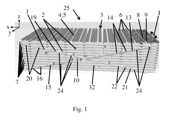
[45] Figure 1 shows an aulorna lea storage and retrieval system 25 ac-
cording to an embodiment of the present disclosure, The automated
storage and retrieval system 25 comprises a track arrangement I or-
ranged in and/or at a rack arrangement 3 in particular at a front face
32 of the rack arrangement 3, and a plurality of self-driven carriages 2.
The track arrangement 1 is configured so that a plurality of self-driven
CA 03150571 2022-02-09
WO 2021/059007
PCT/IB2019/058231
21
carriages 2 can drive along- the -track arrangement 1, e,g. by comprising
tracks having a track width that allows on efficient and Stable driving of
the carriages 2.
[46] The storage rack arrangement 3 for automatically storing and ac-
cessing objects 4 comprises a plurality of storage sites- 5 being arranged
in a plurality of racks 6 extending over a plurality of k storage levels .7,
The:
Storage Sites 5 are accessible by.horiZontal aisle tracks 8 on each storage
level .7., wherein the aisle tracks-8 extend in an aisle direction I along
aisles
9 between the racks 6. The racks 6, the aisles 9, and the aisle: tracks
extend parallel to-eaCh_ other so that the aisle directions I of any pair of
adjacent aisles .9 are parallel to each other. Preferably, the storage Sites.
5 are arranged on a three-dimensional grid. All figures comprise a right--
handed Cartesian coordinate - system with a veriitat ti
forward y-
1_5 axis, and a lateral Therefore,
the aisle direction is directed along
the y-axis.
[47] The track arrangement I connects each storage site 5_ with an in-
teraction site 10 for automatically processing stored Objects 4. and/or au-
120- tornatically issuing objects 4 to be stored. The track arrangement com-
prises in this embodiment as many track levels asstorage i..e, V
=
-k, wherein the traCk levels correspond to the storage levels, The interac-
tion site MIS arranged at a track level that May be denoted as 111nterac-
tiOn-.5ite lever and is more detailed .with reference: to Figure .2, In an al-
25 ternative embodiment, the track arrangement 1.can comprise a .pluttlity-
Jainteradioh sites 10. and/or can: connect each 'storage site 5 with a plu-
rality of interoclion Sites 10. This can iMprove the throughput of the-auto-
mated storage and retrieval System- 25 and provide shorter paths be-
tween an interaction site 10- and any of the storage sites 5.
-30
[48] As shown in Figure 1, the track: arrangementl comprises first one
way ramps 14, second one-way ramps 16, third one-way ramps 20, and
CA 03150571 2022-02-09
WO 2021/059007
PCT/IB2019/058231
22
fourth one-way ramps 22 so that any pair of adjacent storage levels 7 is
connected with each other, Advantageously, the first, second, third, and
fourth one-way ramps 14, 16, 20, 2.2 connecting all Y track levels of the
rack arrangement 3. Thereby, a carriage 2 can each any storage level
7 from an adjacent storage level 7. The track arrangement 1 is detailed
with reference to Figure 2,
[49] Figure 2 shows an enlarged section of the storage and retrieval
sysiern 25 of Figure 1, The track arrangement 1 comprises a first horizontai
one-way track 11 connectable to all aisle tracks 8 on each storage level
7 in a first driving direction li (negative x-direction), and a second hori-
zontal one-way track 12 connectable to all aisle tracks 8 on each stor-
age level 7 in a second driving direction 111 (positive x-direction) opposite
to the first directionll (negative x-direction). The aisle tracks 8 are
b1airec-
5 tional
tracks extending along the y-axis. in an alternative embodiment,
the track arrangement 1 can comprise one-way aisle tracks 8.
[50] The track arrangement 1 comprises a plurality of connection
tracks 31 extending along the y-axis, wherein the connection tracks 31
provide connections between the aisle. tracks 8 and the first horizontal
one-way track 11 and/or the second horizontal one-way track 12. The
connection track 31 serves as a track junction at one or more connec-
tion points 24 and is configured to being traversed by a carriage 2,
wherein the carriage 2 con keep and/or change its driving direction,
preferably by 90 degrees, 180 degrees andior 270 degrees at =any of the
conneclich points 24µ The connection tracks 31 are in this embodiment
unidireciional, but one or more of the connection tracks 31 may be bidi-
rectional in other embodiments, The connection tracks 31 may be com-
posed of a plurality of connection points 24,
51] The connection tracks 31 extend in aisle direction (along the y-
axis), and parailei to each other. The connection tracks 31 each
CA 03150571 2022-02-09
WO 2021/059007
PCT/IB2019/058231
23
comprise a plurality of connection points 24 to connect the horizontal
tracks 11, 12 and/or the one-way ramps 14. 16, 20. 22 with each other.
One of the connection tracks 31 extends from the first horizontal track 11
via the second horizontal track 12 and the'exit point 28 to the entry point
27. Thereby, the connection track 31 connects the first horizontal track
11, the second horizontal track 12, the exit point 28, and the entry point
27, so that a carriage 2 can move from one of said tracks 11, 12 and/or
one-way ramps 14, 16, 20, 22 to another.
0 [52] All first one-way ramps 14 and second one-way ramps 16 lead to-
ward an entry point level 17 (not indicated in Figure 2) of the at least one
interaction site 10. All third one-way romps 20 and fourth one-way ramps
22 lead away from an exit point level 18 (not indicated in Figure 2) of the
at least one interaction site 10. The interaction site 10 can be accessed
5 from the entry point level 17 and left from the exit point level 18. The
entry
point level 17 is the trac,k level at which the interaction site 10 can be
reached by a carriage 2. In this embodiment, a carriage 2 can reach
the interaction site 10 from the entry point level 17 without changing the
track level on which it drives, i.e. the entry point level 17 is the
interaction
20 site level. The entry point level 17 and the exit point level 18 are
here
identical for the interaction site 10, i.e. the entry point 27 and the exit
point 28 are arranged at the same track level, namely at the track level
at which the interaction site 10 is arranged, i.e. the interaction site level.
25 153] In this embodiment, the exit point level 18 is the track level from
where the track level, at which the interaction site 10 is arranged, can
be left via a third one-way ramp 22 and a fourth one-way ramp 22. The
first one-way romp 14 and the second one-way ramp 16 that leads to
the entry point level 17 connects an adjacent track level with the entry
30 point level 17 at an entry point 27 of the interaction site 10 from
which
the interaction site 10 can be reached by a carriage 2. The entry point
27 is arranged at the entry point level 17. The exit point level 18 is
CA 03150571 2022-02-09
WO 2021/059007
PCT/IB2019/058231
24
connected at an exit point 28 of the interaction site 10 via a third one-
way romp 20 and a fourth one-way ramp 22 to an adjacent track level
7, wherein the exit point 28 is arranged in the exit point level 18.
1541 As aiso shown in Figure 1, the first one-way ramps 14 comprise a
first sequence of first ramps 13, the second one-way ramps 16 comprise
a second sequence of second ramps 15, the third one-way ramps 20
comprise a third sequence of third ramps 19 and/or the fourth one-way
ramps 22 comprise a fourth sequence of fourth ramps 21. Subsequent
one-way ramps 14, 16, 20.22 of the first, second, third or fourth sequence
of ramps 13, 15, 19, 21, respectively, are connected lo each other by
one or two horizontal connection points 24. In this embodiment, the first,
second, third or fourth sequence of romps 13, 15, 19, 21 is arranged so
that a carriage 2 can traverse any of said sequence of ramps 1,3, 15, 19,
21 without turns of 180 degrees between ramps. if the available loteral
space does not allow for such a wide track arrangement, the sequences
of ramps 13, 15, 19, 21 may include one or more turns of 180 degrees via
Iwo connection points.
[55) As shown in Figure 2, the track arrangement 1 comprises a one-
way interaction track 26 to connect the entry point 27 of the interaction
site 10 with the interaction site 10 and the interaction site 10 with the exit
point 28 of the interaction site 10, The entry point 27 and the exit point 28
coincide with connection points 24 which connect to a first, second,
third, and fourth one-way romp 14. 16, 20, 22. in this embodiment, when
the entry point 27 and the exit point 28 are arranged at the interaction
site level, the one-way interaction hack 26 is horizontai and part of a
closed one-way i000, wherein the loop is closed by the seco.na horizon-
tal track 12. In other embodiments, the one-way interaction track 26 can
:30 comprise a first, second, third, fourth one-way romp 14, 16, 20, 22.
CA 03150571 2022-02-09
WO 2021/059007
PCT/IB2019/058231
[56] in this embodiment, the first one-way rampS 1,4 with a horizontal
component of a driving direction, transverse to the aisle direction I, to-
words the entry point 27 and the second one-way ramps 16 with the op-
posite horizontal component of a driVing direction; transverse to the aisle
5 direction L towards the entry point 27 have essentially The some
distance,
in the aisle direction 1: to the front face 3:2 of the storage rack arrange-
Ment 3. The third one-way ramps 23 with a horizontal component of a
driving direction, transverse to the aisle direction I, away from the exit
point 28 and the fourth one-way ramps 22 with the opposite horizontal
10 component of a driving direction, transverse to the aisle direction i,
away
from the exit point 28 have: essentially the some distance, in the aisle di-
rection I. to c the front face 32 of the *mace rack arrangement 3. The
first one-way ramps 14 and the second one-way ramps 16 hove a dis-
tance, in the aisle direction I, to the first horizontal one-way track 11 dif-
15 ferent from the distance, in the aisle direction i, of the third one-
way.
ramps 20 and the fourth one-way ramps 22 to the first horizontal one-way
track 11. This means that the first one-way ramps 14 and the second ono-
way romps 16 are arranged in one row of tracks, whereas the third one-
way ramps 20 and the fourth one-way romps flare arranged in another
20 row of tracks. The track rows of the track arrangement 1 may be counted
in forward y-direction, so 1 hat the first horizontal one-way track 11 is here
located in the first track row, the second horizontal one-way track 12 is:
located in The second track row, the third/fourth one-way ramps 20, 22
are located in the third track row, and the first/second one-way ramps
25 14,16 are. located in: the 'fourth track row.
[57] The first horizontal one-way track 11 and the second horizontal
One-Way track 12 extend essentially parallel to each other and trans-
versely to the aisle direction 1õ The first horizontal one-way track 11 and
the second horizontal One-way track 12 are arranged, in the aisle direc-
tiOn between the aisle tracks 8 and the rarnoe,:d one-way tracks 14, 16,
20, 22,
CA 03150571 2022-02-09
WO 2021/059007
PCT/IB2019/058231
26
[581 The self-driven carriages 2 are configured to drive a defined first
path along one-way tracks 11, 12, 26 and first and second one-way
ramps 14, 16 of the track arrangement 1 for automatically transporting a
stored object 4 from a storage site 5 to an interaction site 10. The self-
driven carriages 2 are configured to drive a defined second path along
the one-way tracks 11, 12.26 and third and fourth one-way ramps 20, 22
of the track arrangement for automatically transporting on object 4
from the interaction site 10 to a storage site 5. Therein, the first path and
the second path can comprise common tracks 11., 12, 26, but no com-
mon ramps. Preferably, the automated storage and retrieval system 25
comprises a one or a plurality of cardages 2.
[59] Figure 3 shows a perspective view of an embodiment of an auto-
IS mated storage and retrieval system 25 and a track arrangement i ac-
cording to the present disclosure, comprising exactly one bidirectional
horizontal track 30 connectable to all aisle tracks 8 on each storage level
7. The automated storage and retrieval system 25 is described with refer-
ence to the embodiment which is shown in Figures 1 and 2, wherein the
differences are detailed,
[60] At any storage level 7, the bidirectional horizontal track 30 enables
a carriage 2 to move, on the same storage level 7, from any aisle track 8
to another aisle track 8. The bidirectional horizontal track 30 extends
transversely to the aisle direction I. The bidirectional horizontal track 30
is
arranged, in the aisle direction t. between The aisle tracks 8 and the first
second, third, and/or fourth one-way romps 14, 16, 20, 22. In the aisle
direction L the track arrangement 1 extends with a depth in y-direction
of three track widths, i.e. the width of three connection points 24,
(611 The bidirectional horizontal track 30 is bidirectional to provide short
paths between the interaction site 10 and any of the storage sites 5. in
CA 03150571 2022-02-09
WO 2021/059007
PCT/IB2019/058231
27
an alternative embodiment, the track arrangement 1 tompriSeS first and
second horizontal one-way tracks 11, 12 as Shown in Figs. 1 and 2 instead
Of one bidirectional horizontal track 30 to prevent any potential collision
of carriages 2 when Moving along the said track and/or to provide a
unique first path and/or second path.
[621 The track arrongement 1 comprises a plurality of first sequences
13 of first one-way ramps 14, a plurality of second sequences 15 of sec-
ond one-way ramps 16, a plurality of third sequences 19 of third one-way
romps 20, and a plurality of fourth sequences 21 of fourth one-way ramps
22. Thereby, the track arrangement 1 comprises a plurality of first paths
from any of the storage. sites $: to the interaction site 10,, and Q plurality
of
second paths from the interaction site 10 to any of the storage sites 5. This
can increase the possible throughput of the automated storage and re-
trieval system 25.
[63] in Fig. 3, the interaction level is the third level with the entry point
27 and an exit point 28 on the third level The track arrangement 1 com-
prises a plurality of first, second, third, and fourth sequences of one-way
ramps 13, 15: 19, 21, wherein each sequence comprises two one-way
ramps 14, 16, 20, 22 to reach all five levels of the track arrangement The
second sequence 15 comprises two second one-way ramps 16 directed
upward to the right and arranged in the same track row below and left
of the entry point 27. The third sequence 19 comprises two third one-way
ramps 20 directed upward to the right and arranged in the same track
row track row above and right of the exit point 28. The fourth sequence
21 comprises two fourth one-way ramps 22 directed downward to The
left and arranged in the some track row below and right of the exit point
28. The first sequence 13 differs from the other sequences 15 19, 21 in
30. that there is not sufficient lateral space to right from the entry
point for
the carriage to descend from the fifth fob level. Therefore, one first one-
way ramp 14 of the first sequence 1 between the fourth and third level is
CA 03150571 2022-02-09
WO 2021/059007
PCT/IB2019/058231
28
directed downword to the left ond arranged above and right Of the en-
try point 27 in the same track row of the entry point 27. The other first one-
way romp 14 of the first Sequence 13 between the fifth and fourth level
is directed downWard to the right and arranged in 0 different track'row
than the entry point :27. Therefore, the path of a carriage along the first
sequence 13 implies a 180-degree turn between the two first one-way
ramps 14. The available lateral space and the 'position of the entry point
27 and/or exit point 28 in the track arrangement I determine if and how
Many such 180-degree turns may be needed in which Sequence The
layout of the track arrangement Imay be Chosen to minimise the num-
ber of 180-degree turns as much as possible. However, if need be, the
first, second third, and/or fourth sequences 13,, 15, 19, 21 may comprise
a p!urality of 180-degree turns and may thus define a zich-zag-shaped
oath.
/5
[641 In all shown embodiments, the track arrangement 281s arranged
on a three-dimensional grid, wherein the connection points 24, entry
point 27 and/or exit point 28 define grid points. The grid comprises Z track
Y track rows, and X track columns. The track rows extend irons
verse to the aisle direction I (along x-axis), So that a Sequence of track
rows extends in the aIsle direction lalong y-axis). The frock columns are
defined by a sequence of connection points 24 vertically arranged
above each other (along z-axis), so that o sequence of track columns
extends transverse to the aisle direction {along x7axisL The one,way
ramps 14,, 16, 20, 22 connect adjacent track columns and levels which
each other. The number 7: of track levels equals here the number k of
storage levels 7, Le. k = 5 in Fig, 3. The number of track rows. Y equals
the maximum number of connection points 24 of a connection track 31
in aisle direction I. Le. Y = 3 in Fig. a Additionally, some space in aisle
direction 1, may be provided for arranging the interaction track 26 and
the interaction site 10. in Fig 3, the number X of track columns equals the
number I of frock levels. This is particularly advantageous to reduce the
CA 03150571 2022-02-09
WO 2021/059007
PCT/IB2019/058231
29
number of needed 180-degree turns. However, the carriages 2 may only
be able to securely climb/descend romps with a slope angle of less than
my,ax, so that a minimum track column distance Dmin may be needed to
climb one level height H. wherein Dna?, u7rx. If the available lateral
space does not allow a layout of the track arrangement with at least X
track columns, the number X of track columns can be reduced down to
a minimum number X of 2 at the cost of more 180-degree turns, Prefera-
bly, the driving direction of ramps of the same track row connecting the
same track columns alternates between adjacent levels, Preferably, the
driving direction of ramps between the some levels and connecting the
some track columns differs between the track rows. Preferably, the driv-
ing direction of romps connecting the same leVei5 in the same track row
alternates between adjacent track columns_
[65] The number Y of track rows is counted from the front face 32 of
The rack arrangement 3 forward in x-direction, so that the bidirectional
horizontal track 30 in Fig. 3 is arranged in track row number one. The num-
ber Z of track levels equals the number k of ine storage levels 7, wherein
the bottom storage level has level number one and the top level has
level number five in Fig. 3. In Fig. 3, the number of track columns X is five,
wherein the first track column on the right is track column number one,
the entry point 27 is in track column number two, and the exit point 28 is
in the central third track column. Preferably, the entry point 27 and the
exit point 28 are arranged in adjacent track columns. Preferably, the .en
try point 27 and The exit point 28 are arranaed on the same track level.
[66j in all shown embodiments, the ramps of the same track row are
arranged essentially in parallel to each other, i.e. each extending from
bottom left to top right or vice versa, or each leading from top left to
bottom right or vice versa. In Fig. 3, all ramps of the second track row
lead from top left to bottom right between adjacent levels and track
columns. Analogously, all ramps of the third track row lead from bottom
CA 03150571 2022-02-09
WO 2021/059007
PCT/IB2019/058231
left to lop right between adjacent levels and track columns, in Fitt. 3; only
8 One-way ramps 14, 16, 20, 22 in total would at least be required to con-
nect the entry point 27 and the exit Ohl 28 with any track level. Seven
Of those one-Way ramps 14, 16, 20, 22 are arranged in the third track row
5 and one
first one-way ramp 14 between the fifth and the fourth track
level and the first and second track column. If there was enough lateral
space for another track column right to the first track column, all 8 one-
way ramps 14, 16, 20, 22 could have been arranged in the same track
row, so that the second track row would not be necessary altogether.
10 Fig. 3 shows
32 ramps in total; of which: 16 ramps are arranged in the
second frock row and 16 ramps ore arranged in the third track row.
Therefore, the embodiment of Fig. 3 comprises a redundancy of 24 ad-
ditional ramps that provide alternative options for paths to the entry point
27 or from the exit point 28. This may reduce the, risk of congestions and
15 allow for
more traffic, i.e. for more carriages 2 to be operated simultane-
ously. Moreover the track arrangement I of Fig. 3 could allow for up to
three: more interaction sites 10 lobe' served in porailel, For instance, an-
other interaction site could be orrandea on the third track level between
the fourth and fifth track column, and/or on the first and/or fifth track
20 level
between the second and third: track column and/or between the
fourth and fifth track column,
67) Figures
4 to 7 each show a perspective view of an embodiment
of an automated Storage and retrieval system 25 and a track arrange-
25 ment 1 according to the present disclosure, comprising two unidireo-
fiend horizontal tracks 11, 12 on each storage, level 7. Fig. 4 shows an
embodiment with three interaction sites each having entry points 27 and
exit points On the third track level. The track arrangement / Of Fig. 4 has
altogether 8 levels and 8 track columns with 98 ramps, Wherein 49 ramps.
30 are arranged
in a 7x7 top-left-to-bottom-right configuration in the third
track row and 49 ramps are arranged in a complementary 7x7 bottom-
left-to-top-right configuration in the fourth track row. The redundancy of
CA 03150571 2022-02-09
WO 2021/059007
PCT/IB2019/058231
31
ramps Could allow for up to tour more interaction sites to be served in
parallel and/Or be used to allow for more traffic. In both embodiments
Of Fig. 3 and 4, the Connection tracks 31 in aiSie direction are unidirec-
tionol.
[68] The embodiment shown in Fig. 5 has nine track levels, four track
rows, nine track columns, and three interaction sites 10 with entry points
27 and exit points 28 on the third level, The density of ramps is
significantly
lower than the density of ramps in the embodiments shown in Figs. 3 and
IrO 4. The total number of ramps is 58 in Fig. 5, wherein the some
track row
comprises four ramps between the same track cOlumns connecting
every second pair of levels (1-2, 3-4, =5-6, 7-8) with each other, and
wherein the adjacent track row comprises fair ramps between the same
frock columns connecting the complementary pairs Of levels (2-3, 4-5, 6-
7, 8-9) with each other. The connection frocks 31 in aisle direction are
bidirectional in this Case. The redundancy in this cote would only allow
for one More interaction Site 10 to be served in parallel,
[651 Fig. 5 shows a specific Case of a non-uniform storage level height
to deal With. A Storage rack arrangement 3 may comprise, for instance
due to fire protection regulations Or other COnStraintS, One or more stor-
age levels with a height that differs from the height of the other Storage
levels, in Fig. 5, the storage rack arrangement 3 comprises 8 star-age lev-
els 7, i.e. one level less than the nine track levels of the track arrangement
1. The fourth storage level height it lamer than the other storage level
heights. In order to be able to climb the higher fourth storage level, the
fourth and fifth track level of the track arrangerm3nt 1 are each: half the
height of the fourth storage level height. Therefore, the lowest four track
levels of the track arrangement 1 correspond to the storage levels 1 -4,
whereas the topmost four track levels of the track arrangement 1 ccrre-
spond to the storage levels 5-8. The fifth: track level of the track arrange-
ment 1 is on auxiliary track level between the fourth and fifth storage
level so that the higher storage level height can be climbed without
CA 03150571 2022-02-09
WO 2021/059007
PCT/IB2019/058231
32
exceeding a maximum s ape angle arm,. Therefore, the track arrange-
ment 1 comprises six longer one-way ramps extending between second-
nearest track columns (2-4.. 5-6, 7-8) and between second-nearest track
levels (4-6). These longer ramps have a somewhat smaller slope angle
Than the ordinary ramps and cross the grid without connecting points on
the (auxiliary) fifth track level. As the lateral space at the lateral end
track
columns, i.e. between the first and second track column, and the eighth
and ninth track column, respectively, is not sufficient to accommodate
the longer ramps, the track arrangement 1 comprises at each lateral end
W two ordinary
ramps with a smaller slope angle connected in a zig-zag
configuration by two connecting points on the {auxiliary) fifth track level
and implying each a 180-degree turn. The connecting points in the first
and ninth track column are the only connecting points on the (auxiliary)
fifth track level.
[70] Fig. 6 is on embodiment similar to Fig. 5 without the need for deal-
ing with a non-uniform storage level height. All eight storage heights are
the same in Fig. 6 so that the track arrangement 1 only comprises eight
corresponding track levels and eight track columns. The ramp density is
half of the romp density of Fig. 4; he. 49 ramps to serve three interaction
sites i 0. The same frock row comprises, in an alternating fashion, four or
three romps between the same track columns connecting every second
pair of track levels (1-2, 3-4, 5-6, 7-8 or 2-3, 4-5, 6-7) with each other,
and
wherein the adjacent track row comprises three or four ramps between
the same track columns connecting the complementary pairs of track
levels (2-3, 4-5, 4-7 or 1-2, 3-4, 5-6, 7-8) with each other. The connection
tracks 31 in aisle direction are bidirectional in this case. The redundancy
in this case would only allow for one more interaction site 10 to be served
in parallel.
[71] in Figs. 4-7, at any storage level, the first unidirectional horizontal
one-way track 11 and the second unidirectional horizontal one-way
CA 03150571 2022-02-09
WO 2021/059007
PCT/IB2019/058231
33
track 12 eriCible a carriage 2 to move., at the Same storage level 7, from
any aiSle track 8 to another aisle frock 8. In the aisle direction 1, the
track
arrangement 1 extends by the width of four (Figures 4 to 6) or three (Fig,
tire 7) tracks and/or connection points 24 away from the front face 32 of
the rack arrangement 3. The first horizontal one-way track 11 and the
second: horizontal: one-Way track 12 provide Short paths between the in-
leraction site 30 and any of the storage sites 5.
V21 The frock arrangement I comprises a plurality of interaction sites
10. Any of said interaction sites 10 it connected by tracks 11, 12 and/or
one-way ramps 14, 16, 20, 22 to any of the storage sites 5, In an alterna-
tive embodiment, the track arrangement 1 can comprise a plurolity of
complementary track arrangement sections; wherein any complemen-
tary track arrangement section connects exactly one interaction site 10
1.5 by tracks 31, 12 and/or one-way romps 14, 16., 20, 22 of said complemen-
tary track arrangement section to a particular set of storage sites 5 of the
rock arrangement 3: The complementary track arrangement sections
are arranged so that any storage site 5 is connected to any of the inter--
action sites 10.
[73] The track arrangement I comprises., o plyrdity of first sequences
I 3 of first one-way ramps 14, a plurality of second sequences 15 of sec-
ond one-way ramps 16, a plurality of third sequences I9 of third one-way
tamps 20, Ond a plurality of :fourth sequences 21 of fourth one-way romps
22. Thereby, there is ci plurality of first paths from any of the storage
sites
5 to any of the interaction sites 10, and a plurality of- Second path from
any of the interaction sites 1010 any of the storage sites 5,
[74] The connection points 24, the entry points 27: and the exit points
28 are arranged on a three-dimentional grid OS explained with reference
to Figure 3, wherein the number Y of track *Ws equals the maximum
CA 03150571 2022-02-09
WO 2021/059007
PCT/IB2019/058231
34
number of connection points 24 in aisle direct on 1, therefore Y 4 (Fig-
ures 4 to 6) or Y 3 (Figure 7)..
751 in the embodiment of Figure 7, the, track arrangement 1 comprises
only three track rows, wherein the first unidirectional horizontal one-way
track 11 is arranged in the first track row, the second unidirectional hOri-
zontal one-way track 12 is arranged in the second track row and all
ramps are arranged in the third teat* row. This can Save conStruCtitin
space in the aisle direction 1. Any of the first, second, third, and/or fourth
one-way ramps 14, 16,20, 22 are .cirranged essentially in parallel to each
other in a bottom-left-to-top-right configuration. Without having another
track row with the complimentary top-left-to-bottoM-right configuration.
Certain paths will require that the carriages must do two or more 180-
degree turns with a horizontal path section in between along the first or
15. second horizontal One.-way track 11, 12 to reach a certain track level.
If
there are several options for a path, the optimal path may be chosen
based on the number of needed 180-degree turns, the needed total
length of horizontal path sections and/or current traffic situation. Prefer,
ably, the driving direction of ramps connecting the same track columns
alternates between adjacent track levels. Preferably, the driving direc-
tion of ramps connecting the same track levels alternates between ad-
jacent frock columns,
[761 Figure $ shows .0 perspective view of a section of a track arrange-
mart I according to an embodiment of the present disclosure. The sec-
tion of the track arrangement I of Figure 8 is explained with reference to
the embodiment of Figures 1 and Z wherein the differences of the em-
badirrients ore detailed Such a section of a track arrangement can
be comprised by on embodiment as shown in Figures 1 to 6,
[771 In the seCtion of the track arrangement 1 that is shown in Figure 8,
the track arrangement 1 comprises a first one-way ramp 14 and
CA 03150571 2022-02-09
WO 2021/059007
PCT/IB2019/058231
second one-way ramp 16 each of which leads to on entry point 27 in the
same fourth track row, Le., to a connection point 24 that is arranged on
the entry point level 17. The track arrangement I comprises a third one-
way ramp 20 and a fourth one-way ramp 22 each of which leads away
5 from an exit point 28 in the sate ihird track row, i.e., away from a COn-
nection point 24 that is arranged on the exit point level 18. In this embod-
iment, the entry point level 17 is the track level at which the interaction
site 10 is arranged. The third one-way ramp 20 and the fourth one-way
ramp 22 are arranged in the third track row, Le. closer to the first horizon-
10 101 one-way frock 11 in a direction transverse to the aisle direction I
than
the first one-way romp 14 and the second one-way ramp 16 in the fourth
track row.
[78] In this embodiment, a carriage 2 on a storage level 7 above or
15 below the entry point level 17 can reach the entry point level 17 via
the
first and second one-way ramps 14, 16. The first one-way ramp 14 loads
downwards towards the entry point 27 and the second one-way ramp
I 6 leads upwards to the entry point 27.
20 [79] A carriage 2 on the track level at which the interaction site 10
is.
arranged, can reach from the exit point love/ 18 a storage level 7 above
or below via the third and fourth one-way ramps 20. 22, The third one-
way ramp 20 leads upwards away from the exit point 7.8 and The faurth
one-way ramp 22 leads downwards away from the exit point 28.
[80] Figure 9 shows the track arrangement 1 of Figure 8 in a schematic
top view. The three triangles on the ramps indicate the slope direction
by pointing upward with their tips, whereas the hollow arrows indicate
the driving direction. In the aisle direction 1, four track rows of tracks 11,
12, 14, 16, 20, 22 are arranged in the following order starting from the front
face 32 of the storage rack arrangement 3 the first horizontal one-way
track 11 in the first track row, the second horizontal one-way track 12 in
CA 03150571 2022-02-09
WO 2021/059007
PCT/IB2019/058231
36
the second track row, the third and fourth one-way ramp 20, 22 in the
third track row and the first and the second one-way ramp 14, 16 in the
fourth track row. Said four tracks 11, 12, 14, 16, 20, 22 are connected to
each other by connection points 24 defining a connection track 31 ex-
tend ng in the aisle direction I. At each connection point 24, the car-
riages 2 can efficiently change from one track row to another and be-
tween tracks 11, 12, 14, 16, 20, 22. As can be seen in Figures 8 and 9, the
connection track 31 is preferably aligned with the aisle 9 to reduce the
number of directional changes as well as the horizontal path length as
much as possible.
[81] Figure 10 shows a perspective view of a section of a track arrange-
ment according to on embodiment of the present disclosure. The track
arrangement 1 of Figure 10 is explained with reference to the e rnbodi-
ment of Figures 8 and 9, wherein the differences of the embodiments are
detailed. Such a section of a track arrangement 1 can be comprised by
an embodiment as shown in Figures 7.
[82] Ali ramps 14, 1& 20, 22 as well as both the entry point 27 and the
exit point 28 are arranged in the same third track row here.
[83] Figure 11 shows the embodiment of Figure 10 in a schematic top
view. The three Mangles. on the ramps indicate the slope direction by
pointing upward with their tips, whereas The hollow artrack rows indicate
the driving direction. In the aisle direction L three track rows of tracks 11,
12, 14, 16, 20, 22 are arranged in the following order from the storage
rack arrangement 3: the first horizontal one-way track 11 =n the first track
row, the second horizontal one-way track 12 in the second track row,
and all ramps 14, 16, 20, 22 in the third track row. The track arrangement
1 of this embodiment saves construction space in the aisle direction 1.
CA 03150571 2022-02-09
WO 2021/059007
PCT/IB2019/058231
37
[84] Figure 12 shows 0 perspective view of 0 section of a: track arrange-
ment according to an embodiment of the present disclosure:. The track
arrangement i of Figure 12 is explained with reference to the embodi-
ment of Figures Band 9, wherein the differences of the embodiments are
detailed,
[85] in the section of the track arrangement 1 shown in Figure 12 the
track arrangement 1 comprises a first p.oir of first and second ramps 14,
16 leading to a first entry point 27 in the third track row and g second pair
of first and second ramps 14, 16 leading to g second entry point 27 in the
fourth track row: Thereby, the traffic towards the interaction site 10 can
be increased, because the carriages have two options for reaching the
entry point leve t 17 from the storage level above via first ramp. 1$ or from
the storage level below via second ramps 14,
[861 A carriage 2 at the interaction site 10 can reach another storage
level from an exit paint not shown in Fig. 12. The exit point 28, and/or the
third and/or fourth one-way romps 20, 2'2 can be arranged elSewhere in
the frock arrangement I. The third and/or fourth one-way ramp 20, .22
can be arranged analogous to the first and second one-way ramps 14,
16 (see Figs 18 and 19).
[87) Figure 13 shows the embodiment of Figure 12 in a schematic top
view. The tracks 11, 12, 14, 16 are arranged in four track rows in the foi-
lowing order from the storage rack arrangement 3: the first horizontal
one-way track 11 DI the first track row, the second horizontai one-way
track 12 in the second lrack row, the first pair of ramps .1 4, 16 in the
third
track row and the second pair Of one-way ramps 14, 16 in the fourth track
row. The entry points 27 are arranged, on the connection track 31 in the
third and fourth track row, respectiVely.
CA 03150571 2022-02-09
WO 2021/059007
PCT/IB2019/058231
38
[88] Figure 14 shows a perspective view of a section Of a frock arrange-
ment according to an .embodiment of the present disclosure... The track
arrangement 1 of Figure 14 is explained With reference to the embodi-
ment Of Figures8 and 9, wherein the. differences of the embodiments are
detailed.
[89] In the section of the track. arrangement 1 that: it shown in Figure
14, the track arrangement 1 comprises d first pair of second and third
ramps 16, :20 in the third track row and a second pair of first and second
ramps 14, 16 in the fourth track row, wherein the .connection point 24 in
the third track row and the. entry point 27 in the fourth track row are or-
ranged on the some connection track 31. The connection point 24 may.
serve as entry point :27 when coming from the second ramp 1.6 and as
exit. point 28 When .going to the third romp 20. As already discussed with
reference to Fig. 2, this means that carriages 2 leaving the interact ion
10 to. a storage level above .must take a short path along the horizontal
track 12 in direction ill to reach. the exit point 28. in order to leave the
interaction site. 10 to a storage ieyel below via a fourth romp .22, an e).dt.
point 28 and a fourth romp 22 may be arranged somewhere else (not
shown in Fig. 14) to be reached via the horizontal tracks 11., 12, in on
alternative embodiment, the first pair of. ramps may be .c1 pair of first and
fourth romps 16. 20 in the third track row, so that an exit point 28 and
third ramp 20 may be arranged somewhere els.e. not :shown in Fig. 14)
tor leaVing the interaction site 10 one storage level up.
[90] Figure 15 shows the .embodiment Of figure 14 in a schematic 46.0
view. The tracks 11, 12, 14, 16, 20 are arranged four track lbws in the
following order from the storage rack arrangement 3: the first horizontal
one-way track 11 in the first track row, the second horizontal one-way
track 12 in the second track row, the first pair of Second and third ramps.
16, 20 in the third track row and the second pair of first and second ramps.
14, 16 in fhe fourth track row; The connection point 24 Serving as exit and.
CA 03150571 2022-02-09
WO 2021/059007
PCT/IB2019/058231
39
entry point 27, 28 and the entry point 27 are arranged in the third and
fourth track row, respectively, along the same connection track 31.
(9l) Figure 16 shows a perspective view of a section of a track arrange-
merit according to an embodiment Of the pretent disclosure. The track
arrangement 1 of Figure 16 is explained with reference to the embodi-
ment of Figures 14 and 15, wherein the differences of the embodiments
are detailed.
[92] In the section of the track arrangement I that is shown in Figure
16, the track arrangement 1 comprises a first pair of third and fourth
romps 20, 22 in the third track row and a second pair of first and second
ramps 14õ 16 in the fourth track row, wherein the exit pciint 28 in the third
track row and the entry point 27 in the fourth track row are arranged on
the same connection track 31. As already discussed with reference to
Fig. 2, this means ihot carriages 2 leaving the interaction site 10 to a level
above or below must take a short path along the horizontal track 12 in
direcfio H to reach the exit point 28,
[93] Figure 17 shows the embodiment of Figure 16 in a schematic top
view. The tracks II, 12, 14, 16, 20 are arranged in four track rows in the
following order from the storage rack an-angement 3: the first hOrizOntai
one-way track 11 in the first track row, the second horizontal one-way
track 12 in the second track row, the first pair Of third and fourth ramps
20,22 in the third track row and the second pair Of first and second ramps
14, 16, The enthy, point 27 and the exit point 28 are arranged in the third
and fourth track row, respectively, along the same connection frock 3.1
1941 Figure 18 shows a perspective view of a section of a track arrange-
Ment according to an embodiment of the present disclosure. The track
arrangement I of Figure 18 is explained with reference to the
CA 03150571 2022-02-09
WO 2021/059007
PCT/IB2019/058231
embodiment of Figures 12 and 13, wherein the differences of the em-
bodiments are detailed.
(95] The track arrangement 1 shown in Figures 18 and 19 provides dou-
5 ble capacity and double ramp density compared to Fig. .8. The track
arrangement 1 comprises two entry points in the third and fourth track
row, respectively, arranged on the same connection track 31. Further-
more, the track arrangement 1 comprises two exit points 28 in the third
and fourth track row, respectively, arranged on another connection
10 track 31 of the adjacent track column. The entry point 27 in the third
track
row is connected to first and second tracks 14, 16 in a bottorn-left-ta-top-
right configuration; whereas the entry point 27 in the fourth track row is
connected to first and second tracks 14, 16 in a complementary top-left-
to-bottom-right configuration. Analogously, the exit point 28 in the third
15 track row is connected to third and fourth tracks 20,22 in a bottom-left-
to-top-right configuration, whereas the exit point 28 in the fourth track
row is connected to third an fourth tracks 14, 16 in a complementary
top-left-to-bottom-right configuration.
[96) Figures 20 and 21 each shows a perspective view of an E.,,mbodi-
ment of an outornated storage and retrieval system 25 and a track ar-
rangement 1 according to the present disclosure, comprising three horizontal
tracks i 1, 12, 30 on each storage level 7. The automated storage
and retrieval system 25 is described with reference to the embodiment
25 which is shown in Figures 3, wherein the differences are detailed.
[97] At any storage level 7, the track arrangement I comprises in a first
track row a first horizontal one-way track 11 connectable to all aisle
tracks 8 on each storage level 7 in a first driving direction 11 transverse to
30 the aisle direction L Furthermore, the track arrangement 1 comprises in
a
second track row a second horizontal one-way track 12 connectable to
all aisle tracks 8 on each storage level 7 in a second driving direction 111
CA 03150571 2022-02-09
WO 2021/059007
PCT/IB2019/058231
41
opposite to the first direction 11. An additional unidirectional or bidirec-
tional horizontal track 30 in the third track row may be foreseen to be
connectable to all aisle tracks 8 on each storage level 7. The horizontal
tracks 11, 12, 30 enable a carriage 2 to move, at the same storage level
7, from any aisle track 8 to another aisle track 8. The horizontal tracks 11,
12, 30 extend transversely to the aisle direction and parallel to each
other. The one-way ramps 14, 16, 20, 22 ore arranged in the fourth and
fifth track row. In the aisle direction I. the track arrangement I extends
by the width of five track widths and/or widths of a connection points 24
away from the front face 32 of the rack arrangement 3.
[98] The number Z of track levels equals the number k of storage levels
Z = k = 8. The number Y of track rows duals the maximum number of
connection points 24 in aisle direction 1, therefore, in this embodiment
'15 = 5. The number of track columns X is here the same as the number of
track i.e. X = 8.
[991 Similar to Flo, 6, the track arrangement of Fig. 20 comprises 49
ramps 14, 16, 20, 22 with 24 ramps in the top-left-to-bottom-right config-
uration in the fourth track row and 25 ramps in the complementary bal-
tom-left-to-torighl configuration in the fifth track row for serving three
interaction sites 10 on the third level
[1 poi In Figure 21, the track arrangement 1 comprises a plurality of hold-
ina tracks 33 in an additional sixth track row. A holding track 33 is a sec-
tion of the track arrangement 1 that can be used to hold a carriage 2
idle and/or to park a carriaae, preferably temporarily. This can be useful
for fire protection. The holding track 33 can be a one-way track or a bi-
directional track. The holding track 33 is preferably horizontal. Preferably,
a hoiding track 33 and a horizontal track 11, 12.30 define a closed track
loop as shown in Figure 21. The hoiding tracks 33 may also serve as a
bypass for allowing an additionai oath to the ramps 14, 16, 20, 22. The
CA 03150571 2022-02-09
WO 2021/059007
PCT/IB2019/058231
42
"normal" entry/exit on each storage level to/from the ramps in the fourth
track row is from/to the horizontal track 30 in the third track row. The hold-
ing tracks 33 provide an additional "backward" :entry/exit On each stor-
age level to/from the ramps In the fifth track row from/to the holding
tracks 33 in the third track row. Therefore, the risk Of congestions may be
reduced, because the carriages 2 have further options for entering/exit-
ing the ramps 14, 16, 20, 22 on each storage level.
1011 Figure 22 shows a perspective view Of a section of a arrange-
according to an embodiment of the present disclosure. The track
arrangement 1 of Figure 22 is explained with reference to the embodi-
ment of Figures 12 and 13, wherein the differences of the embodiments
are detailed
[1021 in the section of the track arrangement 1 that is shown in Figures
22 and 23, the track arrangement 1 comprises a first horizontal track 11
in the first .track row, a second horizontal track 12 in the second track row,
bidirectional horizontal track 30 in the third: track row, a first pair of
third
and fourth romps :20, 22 in the fourth track row and a second pair of third
and fourth romps 20 22 in the fifth track row,
1(1)3] A carriage 2 on the interaction site level 7 can reach from the exit
point 28 an another storage level 7 via a third and/or fourth one-way
ramps 20, 22, Thereby, p carriage 2 can, preferably depending on the
occupancy of the third one-way ramps 20 and the fourth one-way
ramps 22, chose between at least two different paths away from the in-
teraction site 10,
11041 In this embodiment, a carriage 2 on a storage level 7 above or
.30 below the
interaction site 10 can reach the entry point .27 via a first one-
way ramp 14 or a second one-way ramp 16 that is not shown in the sec-
tion of the frock arrangement I of Figure 22. The entry point 27, and/or
CA 03150571 2022-02-09
WO 2021/059007
PCT/IB2019/058231
43
the first and/or second one-way ramp 14, 16 can be arranged elsewhere
in the track arrangement 1. The first and/or second one-way ramp 14, 16
Can be arranged analogous to the third Ond fourth one-way romps 20,
22 as shown in Figure :22.
[105] As Shown in Figures 22 and 23, the aisle spacing of the storage rack
arrangement 3 may not exactly correspond to the track column spacing
of the track arrangement 1, which is limited by the maximum slope angle
31,r.,x the carriages 2 can safely climb and descend. The horizontal track
30 may then serve as a bidirectionai adopter track. This is particularly
useful if the difference between oise spacing and track column spacing
is a fraction of a. track width. The horizontal bidirectional adapter track
30 may alternatively be arranged in the first track row; so that the track
30 may be the only track ihat must be customised to the storage rack
13 arrangement 3, whereas The other components of the track orranqe-
ment I may be standard ports,
[106] Figure 24 shows o perspective view Of 0 section of a track arrange-
ment according to on embodiment of the present disclosure. The track
arrangement 1 of Figure 24 is explained with reference to the embodi-
ment Of Figures 22 and 23, wherein the differences of the embodiments
are detailed.
[107] In the section of the track arrangement 1 that is Shown in Figure
24, the track arrangement 1 comprises a first horizontal track 11 in the first
track row, a second horizontal track 12 in the Second track row, a bidi-
rectional horizontal track 30 in the third track row, a first pair Of third
and
fourth ramps 20, 22 in the fourth track row and a second pair of first and
second ramps 14, 16 in the fifth track row. Figure 25 shows the embodi-
ment of Figure 24 in a schematic fop view. In the embodiment of Figures
24 and 25, the horizontal tracks 11, 12, 30 are arranged as explained with
CA 03150571 2022-02-09
WO 2021/059007
PCT/IB2019/058231
44
reference to Figure 22 and 23, and the one-way ramps 14, 16, 20, 22 are
arranged as explained with reference to Figures 16 and 17,
H08) Figure 26 shows a perspective view of an embodiment of an au-
tomated storage and retrieval system 25 and a track arrangement 1 ac-
cording to the present disi.--losure. The automated storage and retrieval
system 25 is described with reference to the embodiment which is shown
in Figures 1 and 2, wherein the differences are detailed.
[109] The track arrangement 1 as shown in Figure 26 has nine track lev-
els, three track columns and two track rows to serve one interaction site
10 at the second track level via interaction track 26. The track arrange-
ment 1 is particulary useful for narrow =storage rack arranclf.-ments .3 with
limited lateral space. The storage rack arrangement 3 has only 5 storage
levels, but the track arrangement comprises 4 additional auxiliary inter-
mediate track levels between the track levels 1-2, 3-4, 5-6 and 7-8. The
track arrangement I thus comprises 16 relatively short one-way ramps
14, 16, 20, 22 that each climb only half a storage level to keep the slope
angle below the maximum slope angle arnx, i.e. the track level distance
of the track arrangement 1 is here half the storage level height Five first
romps 14 connect track levels 8-3 downward, three second ramps 16
connect track levels 1-3 upward, five third ramps 20 connect track levels
3-8 upward, and three fourth ramps 22 connect track levels 3-1 down-
ward, The path along a sequence of ramps 14, 16, 20, 22 may include a
zig-zag sequence with one or more 180-degree turns at the lateral ends.
Le. at the first and third column. A central connection track 31 al the
second track column leads into central aisle tracks 8. The first and third
track column are auxiliary track columns with connection points 24 at the
auxiliary intermediate track levels, where the carriages 2 can make a
180-degree turn to climb or descend a track. level upward or downward.
In this embodiment, horizontal tracks II, 12 with a driving direction trans--
verse to the aisle directonican be dispensed with, because the storage
CA 03150571 2022-02-09
WO 2021/059007
PCT/IB2019/058231
rack arrangement has only one aisle 9. At any storage level 7, the aisle
tracks 8 are connected by the one-way ramps 14, 16, 20, 22 to the inter-
action track 26. In the aisle direction L the track arrangement 1 extends
by the width of Iwo connection points 24 away from the front face 32 of
5 the rack arrangement 3.
[110] Figure 27 shows a perspective view of a section of the track or-
tongement 1 as shown in Figure 26.
10 fill I In the section of the track arrangement 1 that is Shown in Figure
27, the track arrangement 1 comprises a first one-way ramp 14 and a
second one-way ramp 16 each Of which leads to an entry point 27%
to a connection point 24 that is arranged on the entry point level 1:7. The
track arrangement 1 comprises a third one-way ramp 20 and a fourth
15 one-way ramp 22 each of which leads away from an exit point 28, i.e.,
to a connection point 24 that is arranged on the exit point level 18. in this
embodiment, both the entry point level 17 and the exit point level 18 are
located at the fourth track level: i.e. the auxiliary intermediate track level
between the second and third storage level.
[112] Figures 29a,b show, from different ;perspectives, another embodi-
ment of a narrow storage rack arrangement 3 with a track arrangement
1 installed at its front face 32, in contrast to Fig. 26, the storage rack ar-
rangement 3 does not comprise only one single central aisle 9, but two
parallel aisles 9. The ramps 14, 16, 20., 22 of the track arrangement I have
the same configuration as in Fig. 26, However, in order to connect the
two aisle tracks 8 on each storage level 7, one-way horizontal tracks 1 1,
and a bidirectional horizontal frock 30 ore arranged at track rows 1-3
at each storage level 7 to connect connection tracks 31 to the Qisie
tracks 8. The ramps 14, 16, 20, 22 are arranged in the fourth and fifth track
row. The interaction track 26 has a differeni shape and comprises a hold-
ing track 33 in form of a park lane. The holding track 33 allows switching
CA 03150571 2022-02-09
WO 2021/059007
PCT/IB2019/058231
46
the order of carriages 2 in a queue of carriages 2 on the interaction track
26 before being processed at the interaction site 10.
[1131 Figure 30 shows a front view of an automated storage and re-
trieval system according to the embodiment shown in Fig. 5. The front
view shows the distribution of storage sites 4 and aisles 9 along the racks
of the rack arrangement 1.
[I141 Figures 31 to 34 shows a schematic of paths along a track arrange-
ment 1 depending on the position of the entry point 27 and exit point 28,
in each embodiment depending on the occupancy of the system, a
path with the minimum number of 180-degree turns may be chosen. Pref-
erably, in each embodiment, 180-degree turns of each path, as far as
they are necessary, are located only at the lateral ends of the track ar-
rangement 1, i.e. at track column No, 1 and No. X. The shown track ar-
rangement 1 has 9 track levels, 5 track columns, wherein the ramps are
distributed as described before in two track rows.
[115] The track arrangements I according to Figures 31 to 34 each
comprise a first sequence of first ramps track I 3 with a plurality of first
one-way ramps 14, a second sequence of second ramps 15 with a plu-
rality of second one-way ramps 16, a third sequence of third ramps 19
with a piurolity of third one-way ramps 20, and a fourth seouence of
fourth ramps 21 with a plurality of fourth one-way ramps 22. The one-way
ramps 14, 16, 20, 22 and their driving directions are indicated by arrows
pointing towards or away from the interaction site 10.
[1161 According to the embodiment of Figures 31 to 34, an upward path
and a downward path may include one or more 180-degree turns, pref-
erabiy at the lateral end track CdUrIMS.
CA 03150571 2022-02-09
WO 2021/059007
PCT/IB2019/058231
47
[117] In any embodiment, it is also possible that a carriage 2 transports
an object 4 from one storage site 5 to another storage 5 of the track
arrangement 1 without passing an interaction site 10.
[1181 Any of the described track arrangements 1 is arranged so that the
track arrangement 1 can be extended orb trarily by reproducing the
shown track arrangement 1 and/or a section thereof transverse to the
aisle direction I, he.. in the first driving direction 11, periodically. This
makes
the track arrangement 1 modular and adaptable to the size of the rack
arrangement 3.
[119] Figs. 10a,b show another embodiment of a one-way ramp 14, 16,
20, 22. The ramp 14, 16, 20, 22 in Figs. 10a,b comprises a maximum slope
angle of approximately 15 degrees. The ramps 14, 16, 20, 22 comprise a
lower concave portion 104 with a smoothly upwardly rising slope angle
and an upper convex portion 106 with a smoothly upwardly failing slope
angle. There is also a straight portion 108 with a constant maximum slope
angle arranged between the lower concave portion 104 and the upper
convex portion 106. The lateral end points of the ramps 14. 16.20, 22 have
essentially zero slope angle where they connect to the connection points
24. This shape allows fora smooth change of the track level and reduces
the risk of tipping over for the carriage 2 carrying the object 4 in form of
a container.
120] The ramp 14. 16, 20, 22 further comprise securing rails 110 compris-
ing a securing surface 112 facing essentially downward and arranged of
a distance to a running surface 114 on which the wheels 115 of the car-
riage 2 run. The distance is slightly larger' than the dic,,meter of those
wheels of the carriage 2 that extend forwardly and backwardly out of
the contour of the of the carriage 2, so that these are able to run on the
running surface 114 below the securing surface 112. The securing rails 110
have here a C-profile partly embracing the wheels of the carriage 2. The
securing rails 110 here extend along the straight portion 108 having the
CA 03150571 2022-02-09
WO 2021/059007
PCT/IB2019/058231
48
constant maximum slope angle so that tipping over of the carriage 2 is
prevented where the slope angle is largest, if the carriage 2 carrying the
container 4 starts tipping over, for instance due to momentum of con-
tainer load sliding downwards within the container 4, the wheels of the
carriage 2 may shortly lift off from the running surface 114 to abut against
the securing Surface 112. The wheels of the first wheel set 37 will then re-
turn downwards tb run on the running Surface 1 14 again. Thus, the f'?.c.-õur-
.
log roils 110 secure the carriage 2 on steep portions of the ramps 14, 16,
20, 22,
[121] Where, in the foregoing description, integers or elements are
mentioned which hove known, obvious or foreseeable equivalents,
then such equivalents are herein incorporated as it individually set forth.
Reference should be mode to the claims for determining the true
15: scope Of the present disclosure, which should be Construed so as to en-
compass any such equivalents. It will also be appreciated by the
reader that integers Or features Of the disclosure that are described as
optional, preferable, advantageous. Convenient or' the like are optional
and do not limit the Scope Of the independent Claims.
p The obOve embodiments are to be understood as illustrative ex-
amples Of the disclosure. It is to be understood that any feature de-
scribed in relation to any One embodiment may be used alone, or in
combination with other features described, and may also be used in
combination; with one or more features of any other of the embodi-
ments, or any combination of any other of the embodiments. While at
least One eXernoleity embodiment has been shown and described, it
should be understood that other modifications, substitutions and alter-
natives are apparent to one of ordinary skill in the art and may be
changed without ;departing from the scope of the Subject matter de
scribed herein, and this application is intended to cover any adapt a-
lions or variations of the specific embodiments discussed herein.
CA 03150571 2022-02-09
WO 2021/059007
PCT/IB2019/058231
49
[123] In addition, "comprising" does not exclude other elements or
steps, and "a" or "one" does not exclude a plural number, Furthermore,
characteristics or steps which have been described with reference to
one of the above exemplary embodiments may also be used in combi-
nation with other characteristics or steps of other E.Ixernpiary embodi-
ments described above. Method steps may be applied in any order or
in parallel or may constitute a part or a more 0e-tailed version of an-
other method step. It should be understood that there should be em-
bodied within the scope of the patent warranted hereon all such rnodi-
Io float Ions as reasonably and properly come within the scope of the con-
tribution to the art. Such modifications, substitutions and alternatk,,es
can be made without departing from the spirit and scope of the disclo-
sure, which should be determined from ihe appended claims and their
legal equivalents.
[124] List of reference numerals;
track arrangement
2 carriages
3 storage rack arrangement
4 objects
5 storage site
6 rack
7 storage level
8 aisle track
9 aisle
10 interaction site
11 first horizontal one-way track
12 second horizontal one-way track
3 first sequence of first ramps
14 first one-way ramp
15 second sequence of second ramps
1 6 second ramp
CA 03150571 2022-02-09
WO 2021/059007
PCT/IB2019/058231
17 entry point level
exit point level
19 third sequence of third ramps
20 third one-way ramp
5 21 fourth sequence of fourth ramps
22 fourth one-way ramp
connection point
25 automated storage and retrieval system
26 interaction track
10 27 entry point
28 exit point
30 bidirectional horizontal track
31 connection track
32 front face
15 33 holding track
104 lower concave portion
106 upper convex portion
108 straight portion
i 10 securing rails
20 1 1.2 securing surface
i1 4 running surface
115 wheeis of the carriage
isle direction
=
25 Ii first driving direction
UI second driving direction
X number of track columns
number of track rows
30 Z number of track levels