Note: Descriptions are shown in the official language in which they were submitted.
FLUID DELIVERY SYSTEMS FOR USE WITH POWER TOOLS
FIELD
[0001] The present disclosure relates generally to fluid delivery
systems for use
with power tools, and more particularly to fluid delivery systems capable of
supplying
fluid into an airflow path of the power tool to broadcast the fluid as a mist.
BACKGROUND
[0002] Dedicated purpose, gas engine powered backpack misters have been
in use
in agricultural settings since at least the 1950s. The ability to broadcast
fluid
chemicals over distances of 10 to 20 feet was particularly useful for chemical
application in vineyards and orchards. More recently, these backpack misters
have
been used to broadcast mosquito control chemicals and for disinfecting large
spaces.
[0003] In traditional misters, fluid being broadcast travels through
gravity fed
nozzles disposed at the end of a blower tube. The gravity fed nozzles are
generally
mounted at a vertical elevation above the end of the blower tube. Fluid
exiting the
gravity fed nozzles falls from the nozzles in a downward direction. Airflow
generated
by the blower tube breaks up the fluid from the gravity fed nozzles into
droplets
which are carried away by the stream of air. Airstream power and the thrust
force
necessary to break the fluid into discrete droplets for efficient broadcast
are generally
functions of air density, cross-sectional area, and air velocity.
[0004] Airstream power needed to carry droplets is heavily dependent on
air
velocity. As such, many misters on the order of 800 watts have been used to
broadcast
fluid at velocities of up to 195 miles per hour. However, these high-power
misters use
high powered motors and have significant current draws resulting in
undesirably short
run times. Moreover, failure to maintain these misters in a proper orientation
such that
the gravity fed nozzles are disposed above the end of the blower tube can
temporarily
stop broadcasting efforts as the fluid is no longer introduced into the air
stream.
[0005] Accordingly, improved fluid delivery systems are desired in the
art. In
particular, fluid delivery systems which provide consistent broadcast
capabilities with
long operational run times would be advantageous.
1
Date Recue/Date Received 2022-03-01
BRIEF DESCRIPTION
[0006] Aspects and advantages of the invention in accordance with the
present
disclosure will be set forth in part in the following description, or may be
obvious
from the description, or may be learned through practice of the technology.
[0007] In accordance with one embodiment, a fluid delivery system for a
power
tool is provided. The fluid delivery system can include a reservoir configured
to
contain fluid; a manifold comprising a plurality of nozzles configured to be
disposed
at an airflow outlet of the power tool, the manifold being in fluid
communication with
the reservoir; a pump configured to supply fluid from the reservoir to the
manifold to
dispense the fluid through at least some of the plurality of nozzles; and an
attachment
element configured to selectively couple the manifold with the airflow outlet.
[0008] In accordance with another embodiment, a manifold for a fluid
delivery
system configured to be coupled with a power tool is provided. The manifold
can
include a generally ring-shaped structure defining a fluid passageway; a
plurality of
nozzles in fluid communication with the fluid passageway; and a fluid inlet in
fluid
communication with the fluid passageway, the fluid inlet being configured to
receive
fluid from a reservoir, wherein the manifold is configured to dispense the
fluid from
at least one of the plurality of nozzles into an airflow associated with an
airflow outlet
of the power tool.
[0009] In accordance with another embodiment, a backpack fluid sprayer
is
provided. The backpack fluid sprayer can include a power tool including a fan
and an
airflow outlet, the power tool being configured to generate an airflow through
the
airflow outlet; a fluid reservoir configured to contain fluid, the fluid
reservoir being
part of a backpack assembly separate from the power tool; a manifold coupled
to the
power tool adjacent to the airflow outlet, the manifold comprising: a
generally ring-
shaped structure; and a plurality of nozzles disposed along the generally ring-
shaped
structure; and a pump configured to supply fluid from the reservoir to the
plurality of
nozzles, wherein a flow rate of fluid through the plurality of nozzles is
controllable by
adjusting an operating speed of the pump.
[0010] These and other features, aspects and advantages of the present
invention
will become better understood with reference to the following description and
appended claims. The accompanying drawings, which are incorporated in and
2
Date Recue/Date Received 2022-03-01
constitute a part of this specification, illustrate embodiments of the
technology and,
together with the description, serve to explain the principles of the
technology.
BRIEF DESCRIPTION OF THE DRAWINGS
[0011] A full and enabling disclosure of the present invention,
including the best
mode of making and using the present systems and methods, directed to one of
ordinary skill in the art, is set forth in the specification, which makes
reference to the
appended figures, in which:
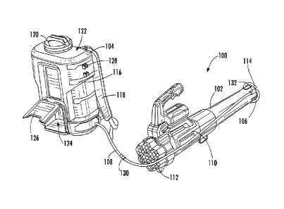
[0012] FIG. 1 is a rear perspective view of a backpack fluid spraying
system in
accordance with an exemplary embodiment of the present disclosure;
[0013] FIG. 2 is a side view of a manifold of the backpack fluid
spraying system
disposed on an airflow outlet of a power tool in accordance with an exemplary
embodiment of the present disclosure;
[0014] FIG. 3 is a perspective view of a manifold in accordance with an
exemplary embodiment of the present disclosure;
[0015] FIG. 4 is a perspective view of a manifold in accordance with
another
exemplary embodiment of the present disclosure;
[0016] FIG. 5 is a schematic front view of a manifold disposed on an
airflow
outlet in accordance with an exemplary embodiment of the present disclosure;
and
[0017] FIG. 6 is a schematic cross-sectional view of a portion of the
manifold in
accordance with an exemplary embodiment of the present disclosure.
DETAILED DESCRIPTION
[0018] Reference now will be made in detail to embodiments of the
present
invention, one or more examples of which are illustrated in the drawings. The
word
"exemplary" is used herein to mean "serving as an example, instance, or
illustration."
Any implementation described herein as "exemplary" is not necessarily to be
construed as preferred or advantageous over other implementations. Moreover,
each
example is provided by way of explanation, rather than limitation of, the
technology.
In fact, it will be apparent to those skilled in the art that modifications
and variations
can be made in the present technology without departing from the scope or
spirit of
the claimed technology. For instance, features illustrated or described as
part of one
3
Date Recue/Date Received 2022-03-01
embodiment can be used with another embodiment to yield a still further
embodiment. Thus, it is intended that the present disclosure covers such
modifications and variations as come within the scope of the appended claims
and
their equivalents. The detailed description uses numerical and letter
designations to
refer to features in the drawings. Like or similar designations in the
drawings and
description have been used to refer to like or similar parts of the invention.
[0019] As used herein, the terms "first", "second", and "third" may be
used
interchangeably to distinguish one component from another and are not intended
to
signify location or importance of the individual components. The singular
forms "a,"
"an," and "the" include plural references unless the context clearly dictates
otherwise.
The terms "coupled," "fixed," "attached to," and the like refer to both direct
coupling,
fixing, or attaching, as well as indirect coupling, fixing, or attaching
through one or
more intermediate components or features, unless otherwise specified herein.
As used
herein, the terms "comprises," "comprising," "includes," "including," "has,"
"having"
or any other variation thereof, are intended to cover a non-exclusive
inclusion. For
example, a process, method, article, or apparatus that comprises a list of
features is
not necessarily limited only to those features but may include other features
not
expressly listed or inherent to such process, method, article, or apparatus.
Further,
unless expressly stated to the contrary, "or" refers to an inclusive- or and
not to an
exclusive- or. For example, a condition A or B is satisfied by any one of the
following: A is true (or present) and B is false (or not present), A is false
(or not
present) and B is true (or present), and both A and B are true (or present).
[0020] Terms of approximation, such as "about," "generally,"
"approximately," or
"substantially," include values within ten percent greater or less than the
stated value.
When used in the context of an angle or direction, such terms include within
ten
degrees greater or less than the stated angle or direction. For example,
"generally
vertical" includes directions within ten degrees of vertical in any direction,
e.g.,
clockwise or counter-clockwise.
[0021] Benefits, other advantages, and solutions to problems are
described below
with regard to specific embodiments. However, the benefits, advantages,
solutions to
problems, and any feature(s) that may cause any benefit, advantage, or
solution to
4
Date Recue/Date Received 2022-03-01
occur or become more pronounced are not to be construed as a critical,
required, or
essential feature of any or all the claims.
[0022] In general, fluid delivery systems described in accordance with
one or
more embodiments herein can be coupled with power tools, such as leaf blowers,
to
broadcast fluid ¨ such as pesticides, herbicides, and the like, over a large
distance
with minimal power draw. The fluid delivery systems can be easily configurable
over
a plurality of operating conditions and be utilized with different power tools
for
different applications.
[0023] Referring now to the drawings, FIG. 1 illustrates a perspective
view of a
fluid spraying system 100 including a power tool 102, a fluid reservoir 104, a
manifold 106, and a connecting hose 108 fluidly coupling the reservoir 104
with the
manifold 106. The power tool 102 can include, for example, a leaf blower
configured
to generate a stream of high-powered airflow. The leaf blower can be gas
powered or
electric powered (e.g., battery powered or connectable to a power outlet). The
leaf
blower can include a housing 110 defining a passageway with an airflow inlet
112 and
an airflow outlet 114. A fan (not illustrated) can be disposed in fluid
communication
with the passageway. The fan can be configured to bias air towards and out of
the
airflow outlet 114. In a particular embodiment, the fan may include an axial
fan
configured to bias airflow through the airflow outlet 114.
[0024] The reservoir 104 can be configured to contain fluid associated
with a
dispensing operation. For instance, the fluid can include an herbicide, a
fungicide, a
germicide, or the like. The reservoir 104 can define indicia 116 which allows
the
operator to determine a fluid level therein. By way of example, the indicia
116 may
include markings on a side of the reservoir 104.
[0025] In certain instances, the fluid spraying system 100 can include
a backpack
spraying system. For example, the reservoir 104 may be part of a backpack
assembly.
The backpack assembly can include, for instance, one or more straps 118 which
allow
the operator to wear the reservoir 104 on their body during fluid dispensing
operations. The straps 118 can be adjustable such that the operator can adjust
the
reservoir 104 to fit their body.
[0026] A cap 120 may be disposed along the reservoir 104 to allow the
operator to
selectively close the reservoir 104. The cap 120 may seal an opening which
permits
Date Recue/Date Received 2022-03-01
the operator to fill the reservoir 104 with fluid. In the illustrated
embodiment, the cap
120 (and opening) are disposed along an upper surface 122 of the reservoir
104. In
other embodiments, the cap 120 (and opening) can be disposed along a side
surface of
the reservoir 104. The cap 120 can include a twist cap, a bayonet connection,
an
interference fit, or the like. One or more vented ports may be included along
the
reservoir 104 to permit atmospheric pressure regulation during withdrawal of
fluid
from the reservoir 104 to prevent collapse of the reservoir 104 and to allow
for a more
consistent draw of fluid therefrom. In an embodiment, the vented port may be
integral
with the cap 120. In another embodiment, the vented port may be part of a body
of the
reservoir 104.
[0027] The reservoir 104 depicted in FIG. 1 includes a receptacle 124
configured
to receive a battery (not shown). A cover 126 may selectively close the
receptacle
124, protecting the battery or even preventing the battery from undesirably
disconnecting from the reservoir 104 during use. In the illustrated
embodiment, the
cover 126 is configured to pivot between an open position (as shown) and a
closed
position. In the open position, the battery may be installed within the
receptacle 124.
In the closed position, the battery may be protected against environmental
damage
and the like. In the illustrated embodiment, the receptacle 124 is shown below
a fluid
containing portion of the reservoir 104. In other embodiments, the receptacle
124 may
be disposed at a different relative position with respect to the fluid
containing portion
of the reservoir 104.
[0028] The battery may be configured to power at least a pump (not
shown). The
pump can be configured to supply fluid from the reservoir 104 to the manifold
106.
By way of example, the pump can include a rotary lobe pump, a cavity pump, a
rotary
gear pump, a piston pump, a diaphragm pump, a screw pump, a gear pump, a
hydraulic pump, a rotary vane pump, a peristaltic pump, or the like. The pump
may be
disposed within the fluid containing portion of the reservoir 104.
Alternatively, the
pump can be disposed outside of the fluid containing portion of the reservoir
104. In
certain instances, the pump can define a variable operating speed. That is,
the speed of
the pump can be adjustable between a plurality of different speeds. In an
embodiment,
the speed of the pump can be infinitely variable. As used herein, infinitely
variable is
intended to refer to a variability without positive stop locations. In such a
manner, the
6
Date Recue/Date Received 2022-03-01
operator can adjust the operational speed of the pump to any desired
operational speed
between a minimum operating speed and a maximum operational speed. In another
embodiment, the speed of the pump may be adjustable between a plurality of
preset
speeds. By way of example, the pump can define a low speed, a medium speed,
and a
high speed. In an embodiment, the operator can selectively change the
operating
speed of the pump using one or more user interfaces. The user interface(s) can
include, for example, one or more of rotary dials or knobs, pivotable levers,
digital
inputs, or the like. The user interface(s) may be disposed on the reservoir
104, the
power tool 102, the connecting hose 108, the manifold 106, or include a
discrete
element such as a wireless remote.
[0029] In an embodiment, the operational speed of the pump can be at
least
partially informed by an operational speed of the power tool 102. For
instance, the
power tool 102 may be in communication with the pump (directly or indirectly)
to
inform the pump of one or more operational conditions of the power tool 102.
Alternatively, the operational speed of the pump can be at least partially
informed by
a fluid type being dispensed, an angular arrangement of the reservoir 104 or
another
element of the fluid spraying system 100, or the like. For example, the
operator may
input information associated with the dispensing operation (e.g., the
dispensed fluid
type, information relating to the dispensing operation being performed, a
desired
broadcast distance or broadcast shape, or the like) which automatically
adjusts the
operational speed of the pump in view of the dispensing operation. In certain
instances, high volume applications may warrant a high operational speed of
the
pump. In other instances, low volume applications may warrant low operational
speed
of the pump.
[0030] The pump may be configured to selectively prevent, or
substantially
prevent, flow of fluid from the reservoir 104 when the pump is in the off
state. For
instance, when not being used to dispense fluid, the pump can prevent
discharge of
fluid from the reservoir 104. In such a manner, fluid flow can be terminated
using
only the pump without the use of any additional control valve(s). In an
embodiment,
the pump can define a normally-closed configuration such that when the
operator
terminates a spraying operation, the pump reverts automatically to a closed
configuration to prevent discharge of fluid from the reservoir 104.
Alternatively, a
7
Date Recue/Date Received 2022-03-01
valve may be disposed in fluid communication with the pump and automatically
revert to a closed configuration when the pump is in the off state. Yet in
other
embodiments, the valve may be manually adjustable between the open and closed
configurations.
[0031] An indicator may inform the operator of the operational speed of
the
pump, a fluid discharge rate (e.g., a volumetric flow rate of fluid being
pumped from
the reservoir 104), a remaining fluid volume level in the reservoir 104, an
anticipated
amount of time until depleting fluid from the reservoir 104, or the like. The
indicator
may be coupled to the reservoir 104, the power tool 102, the connecting hose
108, the
manifold 106, or be part of a stand along element, such as part of the
aforementioned
wireless remote.
[0032] The connecting hose 108 can extend from the reservoir 104 and
fluidly
couple the reservoir 104 with the manifold 106. In an embodiment, the
connecting
hose 108 can extend from a location below the fluid containing portion of the
reservoir 104. In another embodiment, the connecting hose 108 can extend from
a
vertical elevation corresponding to the fluid containing portion of the
reservoir 104.
The connecting hose 108 can be coupled to any one or more of an outer surface
of the
reservoir 104, the power tool 102, or the like by way of one or more couplers
128.
The couplers 128 may allow the operator to selectively route the connecting
hose 108
in a plurality of configurations, for example, based on whether the operator
is left- or
right-handed. The couplers 128 may further facilitate easier storage of the
connecting
hose 108 when the fluid spraying device 100 is not in use.
[0033] The fluid spraying device 100 can include an in-line, quick
connect
interface 130. The in-line, quick connect interface 130 may be disposed along
the
connecting hose 108. The in-line, quick connect interface 130 may include
complementary mating portions which allow the operator to quickly disconnect
the
manifold 106 from the reservoir 104. In certain embodiments, the in-line,
quick
connect interface 130 may automatically move to the closed configuration when
disconnected such that fluid does not leak from the connecting hose 108 when
the
operator disconnects the in-line, quick connect interface 130.
[0034] The connecting hose 108 may be coupled with the manifold 106 at
a fluid
inlet 132 of the manifold 106. The fluid inlet 132 may include an interface
configured
8
Date Recue/Date Received 2022-03-01
to engage with the connecting hose 108 or hardware disposed at the end thereof
For
instance, referring to FIG. 2, the fluid inlet 132 and connecting hose 108 may
be
separated by an intermediary hardware 134. The intermediary hardware 134 can
be
configured to interface between the fluid inlet 132 and connecting hose 108.
By way
of example, the intermediary hardware 134 can include threaded interfaces
configured
to engage with the fluid inlet 132 and connecting hose 108. The intermediary
hardware 134 can define an internal fluid passageway fluidly coupling the
fluid inlet
132 with the connecting hose 108.
[0035] Referring still to FIG. 2, in an embodiment the manifold 106 can
include
an attachment element 136 configured to selectively couple the manifold 106
with the
airflow outlet 114 of the power tool 102. In the illustrated embodiment, the
attachment element 136 includes a plurality of projections extending from the
manifold 106. In certain instances, the projections can be integrally formed
with the
manifold 106. In other instance, the projections can be discrete elements
coupled with
the manifold 106. In an embodiment, the projections can be spaced apart
equidistantly
around a perimeter of the manifold 106.
[0036] In an embodiment, the attachment element 136 can be coupled to
the
airflow outlet 114 through an interference fit. An effective inner diameter of
the
attachment element 136, as measured prior to installation with the airflow
outlet 114,
may be less than an effective outer diameter of the airflow outlet 114. The
operator
can slide the manifold 106 onto the airflow outlet 114 such that the effective
diameter
of the attachment element 136 increases, thus forming the interference fit
with the
airflow outlet 114.
[0037] A guide 138 may be formed along the attachment element 136 to
facilitate
initial installation on the airflow outlet 114. The guide 138 can include, for
instance, a
ramped interface. Using the guide 138, the operator can generally align the
manifold
106 with respect to the airflow outlet 114 prior to translating the manifold
106 or
airflow outlet 114 in a direction toward one another. One or more secondary
attachment elements may be utilized to further secure the manifold 106 on the
airflow
outlet 114. In the illustrated embodiment, the secondary attachment element
includes
a slot 140 disposed along the projection. The slot 140 can be configured to
receive a
fastener. The slot 140 can be configured to align with an opening on the
airflow outlet
9
Date Recue/Date Received 2022-03-01
114 configured to receive the fastener so as to permit the operator to fasten
the
manifold to the airflow outlet 114. Another exemplary secondary attachment
element
includes one or more zip ties which can extend around a perimeter of the
airflow
outlet 114.
[0038] FIG. 3 illustrates a perspective view of the manifold 106 in
accordance
with an embodiment. As depicted, the manifold 106 can include a generally ring-
shaped structure 142 having a plurality of ports 144. The generally ring-
shaped
structure 142 is shown as a discontinuous ring. The discontinuous ring can
define an
end 148 that terminates prior to completing a full 360-degree revolution
(e.g., a closed
circle). By way of example, the discontinuous ring can extend in a circular
manner no
greater than 359 degrees, such as no greater than 355 degrees, such as no
greater than
350 degrees, such as no greater than 345 degrees, such as no greater than 340
degrees,
such as no greater than 335 degrees, such as no greater than 330 degrees, such
as no
greater than 325 degrees, such as no greater than 320 degrees, such as no
greater than
315 degrees, such as no greater than 310 degrees, such as no greater than 305
degrees,
such as no greater than 300 degrees. Terminating the manifold 106 prior to
completing a full 360-degree ring may prevent fluid from recirculating and
traveling
around the manifold 106 without exiting the manifold 106 through the ports
144.
[0039] A gap 145 may be formed between the end 148 of the manifold 106
and
the fluid inlet 132. In certain instances, the gap 145 may have a size
generally
corresponding with a distance between adjacent ports 144 such that the gap 145
does
not impact the relative position of the ports 144 with respect to one another.
In this
regard, the gap 145 does not affect the spatial arrangement of the manifold
106.
[0040] The generally ring-shaped structure 142 can define a fluid
passageway 146
extending from the fluid inlet 132. The fluid passageway 146 can be at least
partially
defined by the generally ring-shaped structure 142 of the manifold 106. The
fluid
passageway 146 can extend around the generally ring-shaped structure 142 and
terminate at, or adjacent to, the end 148 of the generally ring-shaped
structure. The
ports 144 can be in fluid communication with the fluid passageway 146. In this
regard, fluid entering the fluid inlet 132 can pass through the fluid
passageway 146
and enter one or more of the plurality of ports 144 for broadcast.
Date Recue/Date Received 2022-03-01
[0041] As depicted, each one of the ports 144 can include an opening
150 fluidly
coupling the fluid passageway 146 with an external environment. Each one of
the
openings 150 can define a centerline, such as centerline Cp. The manifold 106
can
define a centerline Cm. In an embodiment, the centerline Cm can be a central
axis of
the generally ring-shaped structure 142. In certain instances, the generally
ring-shaped
structure 142 can lie along a plane and the centerline Cm can extend
perpendicular to
the plane.
[0042] In an embodiment, the centerline Cp of at least one of the
openings 150 can
be canted relative to the centerline Cm of the manifold 106. That is, the
centerline Cp
of at least one of the openings 150 can be angularly offset from the
centerline Cm of
the manifold 106. By way of example, Cp and Cm can be angularly offset by at
least 1
degree, such as by at least 2 degrees, such as by at least 3 degrees, such as
by at least
4 degrees, such as by at least 5 degrees, such as by at least 10 degrees, such
as by at
least 15 degrees, such as by at least 20 degrees. In an embodiment, the
centerlines Cp
and Cm can intersect one another at an intersection point 152. In a more
particular
embodiment, the centerlines Cp of at least two of the openings 150 can
intersect the
centerline Cm of the manifold 106 at the same intersection point 152. In yet a
more
particular embodiment, the centerlines Cp of all of the openings 150 can
intersect the
centerline Cm of the manifold 106 at the same intersection point 152. In this
regard, a
relative canted angle of each of the openings 150 can be approximately equal.
[0043] In certain instances, the canted openings 150 can be configured
to dispense
fluid towards a center of the airflow path a distance downstream of the
airflow outlet
114. That is, the canted openings 150 can broadcast fluid in front of the
airflow outlet
114 a distance downstream of the manifold 106. The effective distance fluid is
dispensed downstream of the airflow outlet 114 may vary based at least in part
on the
volumetric flow rate of the fluid, fluid density, fluid flow rate
characteristics
particular to the fluid being dispensed, speed of airflow at the airflow
outlet 114,
diameter of the manifold 106, diameter of the airflow outlet 114, or any
combination
thereof Canting the openings 150 so that they dispense fluid deeper into the
airflow
path, i.e., closer to the centerline Cm, may increase broadcast effectiveness,
distance,
or both. For example, the flow rate of air exiting the airflow outlet 114 may
generally
increase from the perimeter of the airflow outlet 114 towards the centerline
Cm as a
11
Date Recue/Date Received 2022-03-01
result of drag incurred on the airflow by the walls of the power tool 102.
Biasing fluid
closer to the centerline Cm may thus increase the power of the airflow
exhibited on the
fluid, thereby increasing solubility of the particles in the air (i.e., the
air can more
readily break the fluid into droplets) or even increasing broadcast distance.
[0044] In the illustrated embodiment, the manifold 106 includes six
ports 144.
The six ports 144 are equally, or generally equally, spaced apart from one
another
around the circumference of the generally ring-shaped structure 142. Moreover,
the
six ports 144 are generally equally shaped, sized, and oriented as measured
with
respect to one another and the centerline Cm. Referring to FIG. 4, in
accordance with
another exemplary embodiment, the manifold 106 can include 12 ports 144. The
ports
144 depicted in FIG. 4 include two sets of ports ¨ a first set of ports 154
and a second
set of ports 156. The first and second sets of ports 154 and 156 can define
different
sizes, different shapes, different orientations, or any combination thereof as
measured
with respect to one another. For instance, the first set of ports 154 can be
canted
relative to the centerline Cm at a first relative angle while the second set
of ports 154
are canted relative to the centerline Cm at a second relative angle different
from the
first relative angle. By way of example, the difference of relative angles
between the
first and second set of ports 154 and 156, as measured with respect to the
centerline
Cm, can be at least 1 degree, such as at least 2 degrees, such as at least 3
degrees, such
as at least 4 degrees, such as at least 5 degrees, such as at least 10
degrees. This
difference in angular offset with respect to the centerline Cm can increase
uniformity
of the fluid dispense pattern. For example, while the first set of fluid ports
154
broadcast the fluid to a first intersection point 152A, the second set of
fluid ports 156
can broadcast the fluid to a second intersection point 152B different from the
first
intersection point 152A. Thus, the fluid can be broadcast at different depths
of the
airflow path. In other embodiments, the ports 144 can further define a third
set of
ports (not shown), a fourth set of ports (not shown), or any other number of
sets of
ports. Additionally, in certain instances, the ports 144 may be individually
different
from one another such that no two ports share the same size, shape, or
orientation.
[0045] In the illustrated embodiment, the ports 144 of the first and
second sets of
ports 154 and 156 are staggered with respect to one another. That is, each
pair of
adjacent ports of the first set of ports 154 is spaced apart by one of the
second set of
12
Date Recue/Date Received 2022-03-01
ports 156. In other embodiment, the staggering configuration may be different.
For
instance, each pair of adjacent ports of the first set of ports 154 may be
spaced apart
by two of the second set of ports 156. In another embodiment, ports 144
disposed on a
first side of the generally ring-shaped structure 142 can define a first
characteristic
and ports 144 disposed on a second side of the generally ring-shaped structure
142
can define a second characteristic different from the first characteristic.
Other patterns
and arrangements of ports 144 are contemplated herein without deviating from
the
scope of the disclosure.
[0046] In an
embodiment, the ports 144 can be disposed around at least half of the
perimeter of the airflow outlet 114. That is, the ports 144 do not need to be
grouped
together in a small area of the airflow outlet 114 as with traditional misting
assemblies. Referring, for example, to FIG. 5, the airflow outlet 114 can
define a first
half 158 and a second half 160. The first and second halves 158 and 160 can be
separated by a dividing line 162 bisecting the airflow outlet 114. In an
embodiment
the dividing line 162 can extend generally horizontally such that the first
half 158 is
disposed above the second half 160. In an embodiment, the manifold 106 can
include
at least one port 144 disposed in the first half 158 and at least one port 144
disposed in
the second half 160. In a more particular embodiment, the manifold 106 can
include at
least two ports 144 disposed in the first half 158 and at least two ports 144
disposed in
the second half 160. In another embodiment, the manifold 106 can include at
least one
port 144 disposed in the first half 158 and at least two ports 144 disposed in
the
second half 160. In yet another embodiment, the manifold 106 can include at
least two
ports 144 disposed in the first half 158 and at least one port 144 disposed in
the
second half 160. In an embodiment, the number of ports 144 in the first half
158 of
the manifold 106 can be different than the number of ports 144 in the second
half 160
of the manifold 106. In another embodiment, the number of ports 144 in the
first half
158 can be the same as the number of ports 144 in the second half 160. In an
embodiment, the ports 144 can be arranged so as to be reflectively symmetrical
about
the dividing line 162. In another embodiment, the ports 144 can be
rotationally
symmetrical about the centerline Cm. However, rotational or reflective
symmetry is
not required in accordance with all of the embodiments described herein. In
certain
instances, the dividing line 162 can intersect one or more of the ports 144.
13
Date Recue/Date Received 2022-03-01
[0047] Referring to FIG. 6, in an embodiment, at least one of the ports
144 can be
configured to receive a nozzle 164. The nozzle 164 can be interchangeable with
the
port 144. Moreover, the nozzle 164 can be removable from the port 144. For
instance,
the nozzle 164 may be threadably engaged with the port 144. Other exemplary
methods of interfacing the nozzle 164 and port 144 include an interference
fit,
adhesive(s), bayonet connections, and the like. 0-rings (not shown) may seal
the
interface between the nozzles 164 and the ports 144.
[0048] In an embodiment, the nozzle 164 can be selected from a group of
nozzles
164 each defining a different attribute or characteristic as compared to one
another.
For instance, the group of nozzles 164 can include a first nozzle and a second
nozzle.
The first nozzle can define a first effective diameter configured to pass
fluid
therethrough and the second nozzle can define a second effective diameter
configured
to pass fluid therethrough that is different from the first effective
diameter. By way of
another non-limiting example, a relative pitch of the nozzle (i.e., the angle
of taper of
an opening in the nozzle) may vary between nozzles. In this regard, the fluid
flow
characteristics of the manifold 106, or even each individual port 144, can be
customized based on the spraying application.
[0049] In certain instances, at least one of the nozzles 164 can be
selectively
closable. That is, the at least one nozzle 164 can be configured to be fluidly
isolated
from the external environment. This may be desirable, for example, when an
operator
wishes to decrease the number of ports 144 dispensing fluid. Alternatively,
the
operator may decide to selectively close ports 144 associated with the first
or second
halves 158 or 160 in view of an anticipated operation, environmental
conditions such
as wind and the like, or in view of other considerations. In certain
instances,
selectively closing the port(s) 144 may be performed by using a plug 166. The
plug
166 may be insertable in the nozzle 164 to prevent dispensing of fluid. In
other
instances, selectively closing the port(s) 144 may be performed by operating
on the
port 144 or nozzle 164. For instance, by way of non-limiting example, the
operator
can close the port 144 by rotating the nozzle 164 to a closed position.
[0050] In an embodiment, the manifold 106 can have a single-piece
construction.
That is, for example, the manifold 106 can have a unitary construction. In
certain
instances, the manifold 106 can be formed using a water injection technique
(WIT).
14
Date Recue/Date Received 2022-03-01
The WIT process is capable of making hollow, or semi-hollow, parts by
injecting
water into a molded part while the material is still molten, or semi-molten.
Use of
WIT processes in forming the manifold 106 can reduce product cycle time by
more
rapidly cooling the part.
[0051] In certain instances, the fluid spraying system 100 may be
configured to be
retrofit on an existing power tool 102. That is, the power tool 102 need not
have any
specific arrangement for use of the fluid spraying system 100. In this regard,
the
operator can use the fluid spraying system 100 on a range of different power
tools.
For example, in additional to being usable with a leaf blower, the fluid
spraying
system 100 may be utilized with a weed sprayer. Moreover, the fluid spraying
system
100 may be configurable to be used as a stand-alone unit, independent of the
power
tool 102. For instance, the intermediary hardware 134 may have a rigid
construction
such that the operator can hold the manifold 106 through the intermediary
hardware
134 independent of an underlying power tool 102. Using the fluid spraying
system
100 without the power tool 102 may allow the operator to create a more
localized mist
having a smaller broadcast distance. That is, without generation of an airflow
by the
power tool 102, the broadcast distance can be defined by fluid spraying system
100
(e.g., the operational speed and capabilities of the pump).
[0052] One limitation of traditional dispensing assemblies is the use
of gravity fed
nozzles for dispensing fluid into an airflow path. These gravity fed systems
typically
only dispense fluid at desired flow rates when the nozzles are disposed in an
ideal
orientation with respect to gravity (i.e., oriented downward and disposed
above the
airflow path). Flipping the nozzles upside down such that they are disposed
below the
airflow path greatly decreases fluid flow rate, thereby effecting the
broadcast
operation. To overcome these challenges, embodiments described herein utilize
a
manifold extending around at least a majority of the airflow outlet 114. Thus,
fluid
can exit the ports 144 regardless of orientation. Moreover, by pressurizing
the fluid
using the pump, the fluid can be dispensed at a constant, or generally
constant, flow
rate through all of the ports 144 regardless of relative orientation of the
manifold 106
with respect to gravity. As a result, the fluid spraying system 100 described
in herein
can operate without electrostatically charging the fluid. That is, the fluid
is not
electrostatically, or otherwise, charged for effective broadcast. To the
contrary,
Date Recue/Date Received 2022-03-01
traditional misting assemblies frequently require electrostatically charged
fluid to
associate the fluid into the airflow path. This can be the result of the fluid
not fully
entering the airflow path as a result of, e.g., gravity fed ports disposed
above the
blower end. While effective at creating mists, electrostatically charged fluid
more
readily interacts with the environment upon broadcast, resulting in less than
desirable
misting patterns. Moreover, electrostatically charged fluid may not settle
equally onto
all objects and surfaces in the broadcast range.
[0053] Further aspects of the invention are provided by one or more of
the
following embodiments:
[0054] Embodiment 1. A fluid delivery system for a power tool, the
fluid delivery
system comprising: a reservoir configured to contain fluid; a manifold
comprising a
plurality of nozzles configured to be disposed at an airflow outlet of the
power tool,
the manifold being in fluid communication with the reservoir; a pump
configured to
supply fluid from the reservoir to the manifold to dispense the fluid through
at least
some of the plurality of nozzles; and an attachment element configured to
selectively
couple the manifold with the airflow outlet.
[0055] Embodiment 2. The fluid delivery system of any one or more of
the
embodiments, wherein the reservoir is part of a backpack assembly configured
to be
worn by an operator during use of the power tool.
[0056] Embodiment 3. The fluid delivery system of any one or more of
the
embodiments, wherein the plurality of nozzles comprises at least two nozzles,
wherein one of the at least two nozzles is configured to be disposed in a
first half of
the airflow outlet, and wherein another one of the at least two nozzles is
configured to
be disposed in a second half of the airflow outlet.
[0057] Embodiment 4. The fluid delivery system of any one or more of
the
embodiments, wherein each of the plurality of nozzles includes an opening
configured
to dispense fluid, wherein the openings of the nozzles define centerlines, and
wherein
the centerlines of at least two of the plurality of nozzles intersect at a
location
generally along a centerline of the airflow outlet.
[0058] Embodiment 5. The fluid delivery system of any one or more of
the
embodiments, wherein the manifold comprises a generally ring-shaped structure,
and
16
Date Recue/Date Received 2022-03-01
wherein at least some of the plurality of nozzles are generally equally spaced
apart
from one another along the generally ring-shaped structure.
[0059] Embodiment 6. The fluid delivery system of any one or more of
the
embodiments, wherein at least one of the plurality of nozzles is selectively
closable.
[0060] Embodiment 7. The fluid delivery system of any one or more of
the
embodiments, wherein the manifold is coupled to the reservoir through an in-
line,
quick connect interface.
[0061] Embodiment 8. The fluid delivery system of any one or more of
the
embodiments, wherein a flow rate of dispensed fluid is controllable by
adjusting an
operating speed of the pump.
[0062] Embodiment 9. The fluid delivery system of any one or more of
the
embodiments, wherein the attachment element comprises a plurality of
projections
extending from the manifold and configured to form an interference fit with an
outer
surface of the airflow outlet of the power tool.
[0063] Embodiment 10. The fluid delivery system of any one or more of
the
embodiments, wherein the fluid delivery system is separate from the power
tool, and
wherein the fluid delivery system is configurable to operate with a plurality
of
different types of power tools.
[0064] Embodiment 11. A manifold for a fluid delivery system configured
to be
coupled with a power tool, the manifold comprising: a generally ring-shaped
structure
defining a fluid passageway; a plurality of nozzles in fluid communication
with the
fluid passageway; and a fluid inlet in fluid communication with the fluid
passageway,
the fluid inlet being configured to receive fluid from a reservoir, wherein
the manifold
is configured to dispense the fluid from at least one of the plurality of
nozzles into an
airflow associated with an airflow outlet of the power tool.
[0065] Embodiment 12. The manifold of any one or more of the
embodiments,
wherein at least some of the plurality of nozzles are generally equally spaced
apart
from one another along the generally ring-shaped structure.
[0066] Embodiment 13. The manifold of any one or more of the
embodiments,
wherein at least one of the plurality of nozzles is selectively closable.
[0067] Embodiment 14. The manifold of any one or more of the
embodiments,
wherein the plurality of nozzles each include an opening defining a
centerline, and
17
Date Recue/Date Received 2022-03-01
wherein the centerline of at least one of the nozzles is canted relative to a
centerline of
the manifold.
[0068] Embodiment 15. The manifold of any one or more of the
embodiments,
wherein at least one of the plurality of nozzles is disposed in a first half
of the
generally ring-shaped structure, and wherein at least one of the plurality of
nozzles is
disposed in a second half of the generally ring-shaped structure.
[0069] Embodiment 16. The manifold of any one or more of the
embodiments,
wherein the manifold further comprises an attachment element configured to
selectively couple the manifold with the airflow outlet, and wherein the
attachment
element is integral with the generally ring-shaped structure.
[0070] Embodiment 17. A backpack fluid sprayer comprising: a power tool
including a fan and an airflow outlet, the power tool being configured to
generate an
airflow through the airflow outlet; a fluid reservoir configured to contain
fluid, the
fluid reservoir being part of a backpack assembly separate from the power
tool; a
manifold coupled to the power tool adjacent to the airflow outlet, the
manifold
comprising: a generally ring-shaped structure; and a plurality of nozzles
disposed
along the generally ring-shaped structure; and a pump configured to supply
fluid from
the reservoir to the plurality of nozzles, wherein a flow rate of fluid
through the
plurality of nozzles is controllable by adjusting an operating speed of the
pump.
[0071] Embodiment 18. The backpack fluid sprayer of any one or more of
the
embodiments, wherein at least one of the plurality of nozzles is disposed in a
first half
of the generally ring-shaped structure, and wherein at least one of the
plurality of
nozzles is disposed in a second half of the generally ring-shaped structure.
[0072] Embodiment 19. The backpack fluid sprayer of any one or more of
the
embodiments, wherein the manifold is coupled to the reservoir through an in-
line,
quick connect interface.
[0073] Embodiment 20. The backpack fluid sprayer of any one or more of
the
embodiments, wherein the manifold is formed using water injection.
[0074] This written description uses examples to disclose the
invention, including
the best mode, and also to enable any person skilled in the art to practice
the
invention, including making and using any devices or systems and performing
any
incorporated methods. The patentable scope of the invention is defined by the
claims,
18
Date Recue/Date Received 2022-03-01
and may include other examples that occur to those skilled in the art. Such
other
examples are intended to be within the scope of the claims if they include
structural
elements that do not differ from the literal language of the claims, or if
they include
equivalent structural elements with insubstantial differences from the literal
language
of the claims.
19
Date Recue/Date Received 2022-03-01