Note: Descriptions are shown in the official language in which they were submitted.
CA 03151093 2022-02-15
WO 2021/013655
PCT/EP2020/070028
1. Title of the Invention:
System and method for GUI development and deployment in a real
time system
Complete Specification:
The following specification describes and ascertains the nature of this
invention
and the manner in which it is to be performed.
1
CA 03151093 2022-02-15
WO 2021/013655
PCT/EP2020/070028
Field of the invention
[0001] Present invention is related to a system and a method for development
and
deployment of flexible, dynamically editable and load-balanced GUI in a
connected
real time system.
Background of the invention
[0002] Typically, the UX designers create all digital assets on their PC/Mac
which
includes screen flows and contents (images and texts) using digital content
creation
software tools like Sketch, Photoshop, etc. However, even after creating the
complete
visualization they need to create written and diagrammatic
specification/requirements
documents so that it could be converted into a software that can be executed
on a target
device with appropriate performance and load balancing. This involves a lot of
effort
to understand complex GUI behaviors using the specification documentation in
order
to convert the specification to target hardware specific visualization and
performance.
This results in a lot of iterations, delays, visual defects and performance
defects.
[0003] Presently most of the software products are capable of performing basic
image
and text import from GUI designs and generate GUI software for these basic
screens.
However, these products do not generate and provide live editing of the GUI
contents
in real time. The products are also not capable of monitoring the computing
resource
load on the connected real time system and generate GUI software that is
capable of
balancing the computing resource load.
[0004] Moreover, there are a few software products are available to convert
digital
assets like images and text from GUI designs to partial GUI software
components or
basic HTML pages or GUI prototypes. However these software need to be ported
to
the target hardware manually and later need to be tuned for performance by
2
CA 03151093 2022-02-15
WO 2021/013655
PCT/EP2020/070028
developers. Besides, this process needs to be repeated every time there is a
change in
the GUI screen flows or screen visualization or when the input sources change.
[0005] According to an US application numbered US6496202B, a method and
apparatus for generating a graphical user interface. This patent provides a
design using
which a GUI can change its visualization depending on how the user interacts
with the
application in the field. For example, when a user clicks a button, a part of
the
screen/fragment/control can be switched off and a new screen/fragment/control
can be
added automatically. However someone needs to explicitly decide what the
behavior
shall be when the event happens and once this is specified the design helps in
generating the GUI that satisfies the new requirements. However, the disclosed
system
do not allow the GUI behaviors or specification itself to be edited in real
time on the
connected real time device. It also does not optimize the GUI based on the
performance
and load on the real time system.
[0006] Hence, there is a need of a solution to capture the inputs from the UX
designers
from various mediums, tools and formats and then generate machine
understandable
GUI specification that is capable of being directly interpreted and executed
on the
connected real time system without any manual involvement.
Brief description of the accompanying drawing
[0007] Different modes of the invention is disclosed in detail in the
description and
illustrated in the accompanying drawings:
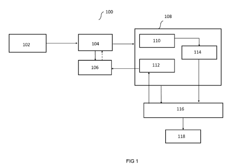
[0008] Figure 1 is a block diagram illustrating a system for deployment of
dynamically
editable GUI on a connected real-time device, according to the aspects of the
present
invention; and
3
CA 03151093 2022-02-15
WO 2021/013655
PCT/EP2020/070028
[0009] FIG. 2 is an example process for deployment of dynamically editable GUI
on
a connected real-time device using the system of FIG. 1, according to the
aspects of
the present technique.
Detailed description of the embodiments
[0010] Fig. 1 illustrates overall structure and components involved in a
system 100, in
which example embodiments of the present invention may be deployed. The system
100 is adapted to automatically deploy the machine executable graphical user
interface
(hereinafter "GUI") specifications on a connected real time device. The system
100
may be deployed in various environments. For example, the system 100 can be
deployed on a cloud or a server which can then service the requests/inputs
from several
clients. The system 100 includes an input module 102, a GUI specification
generator
104, a GUI configurator 106, a real-time module 108, a rendering module 116
and
output module 118. Each component is described in further detail below.
[0011] The input module 102 is configured to receive a plurality of GUI inputs
from
a user, herein UX designer. In one embodiment, the plurality of GUI inputs may
be
captured from several mediums such as images via camera, screenshots, frame-
grabber, video, audio, digital content creation tools like Photoshop, Sketch,
and the
like. In this embodiment, the GUI inputs may be live feed or recorded
playback.
[0012] The input module 102 is further configured to convert the plurality of
GUI
inputs to digital formats, data and meta-data which are relevant for GUI
development.
In addition, the plurality of GUI inputs are processed to identify the
building blocks of
a GUI such as GUI screen flows, GUI layouts, GUI contents and the like. In one
example, pattern matching, image comparisons, context aware content
recognition,
machine learning techniques may be used to perform the identification of the
building
blocks of the GUI. However, a variety of other identification techniques may
be
envisaged.
4
CA 03151093 2022-02-15
WO 2021/013655
PCT/EP2020/070028
[0013] The GUI Specification generator 104 is configured to parse the
processed GUI
inputs and generate machine understandable graphical user interface
specification
from the plurality of graphical user interface inputs. In one embodiment, the
processed
GUI inputs is the digital GUI data and meta-data. The GUI Specification
generator
104 is further configured to generate machine understandable specifications
for GUI
flows, screens and contents. The generated GUI specifications are then
uploaded onto
a storage module 110 of the real-time module 108. Furthermore, after
identifying the
building blocks of the GUI, the blocks are stored digitally with appropriate
meta-data
which is used to describe the GUI. The digital GUI data along with appropriate
meta-
data is then passed onto the GUI specification generator 104, which can
further act on
the plurality of GUI inputs. The GUI specification generator 104 may be
deployed in
various environments. For example, it can be deployed on a cloud or a server
which
can then service the requests/inputs from several clients.
[0014] The GUI Configurator 106 is configured to inject performance load
balancing
parameters and configuration data along with the GUI configuration data. The
GUI
Configurator 106 is further configured to parse the digital asset data and
meta-data
related to the GUI. In one embodiment, after the parsing is done, the GUI
configurator
106 is further configured to enable the UX designer/user to edit the GUI
flows, layouts
and contents in the connected real time system and see the result on an output
module
118 in real time.
[0015] In an alternate embodiment, the GUI configurator 106 is integrated to a
content
management system (CMS) server. Further, the GUI configurator 106 configured
to
receive several dynamic updates from a content management system (CMS) server
for
the latest digital assets.
5
CA 03151093 2022-02-15
WO 2021/013655
PCT/EP2020/070028
[0016] The real-time module 108 configured to automatically deploy the machine
executable GUI specification on the connected real time system and edit the
GUI
inputs in real time. In an embodiment the real-time module 108 may be deployed
in
various environments. For example, the real-time module 108 can be deployed
over,
websites, desktop, PC's, MAC or the like. The real-time module 108 includes a
storage module 110, load balancer 112 and a loading engine 114. Each component
is
described in further detail below.
[0017] The storage module 110 is configured to store the machine
understandable GUI
specification, generated by the GUI specification generator 104. In one
embodiment,
the machine understandable GUI specification includes GUI screen flows,
layouts and
contents. The storage module 100 is configured to store the machine
understandable
GUI specification in the form of XMLs, binaries, configuration parameters,
tables,
OpenGL/WebGLNulkan/OpenVG/2D graphics lib invocations, and the like.
[0018] The load balancer 112 is configured to collect real time computing
resource
loads from the connected real time system. The load balancer 112 runs on the
real
time system and continuously keeps monitoring the load.
[0019] The loading engine 114 is configured to ensure that the graphical user
interface
specification is loaded from the storage module (110) and forwarded to a
rendering
module (116). The rendering module 116 is configured to execute the generated
machine understandable GUI specification on a real time system. In one
embodiment,
when the GUI specifications such as screen flow, layouts and contents are
executed
on the rendering module 116, the load is monitored by the load balancer 112
and sent
to the GUI Configurator 106 in real time as a load balancing configuration.
The GUI
Configurator 106 uses the load balancing configuration to optimize the GUI
configuration Flow, layout and contents. In one example, the computing
resource load
6
CA 03151093 2022-02-15
WO 2021/013655
PCT/EP2020/070028
on the connected real time system is monitored and its usage is evaluated in
real time
to derive the optimal load balancing strategy.
[0020] In another embodiment, the GUI Configurator 106 is interactively
connected
with the load balancer 112 on the connected real time device. Based on the
load
balancing configuration data received from the load balancer 112, the GUI
Configurator 106 injects performance load balancing parameters and
configuration
data along with the GUI flow, layouts and content configuration data. Further,
this
data flows to the GUI Specification generator 104 which uses the configuration
data
to generate a load balanced application. In one embodiment, This load balanced
GUI
configuration is then sent to the GUI Specification generator which in turn
generates
the machine understandable GUI specification that is then stored on the
storage
module 110 of the connected real time system.
[0021] FIG. 2 is an example process 200 for deployment of dynamically editable
GUI
on a connected real-time device using the system 100 of FIG. 1, according to
the
aspects of the present technique.
[0022] At step 202, a plurality of GUI inputs are received, to identify the
building
blocks of the graphical user interface. In an embodiment, the plurality of GUI
inputs
may be captured from several mediums such as images via camera, screenshots,
frame-
grabber, video, audio, digital content creation tools like Photoshop, Sketch,
and the
like. In some embodiments, the GUI inputs are accessed from other locations
such as
from an offline image repository, cloud storage and so forth. In an
embodiment, the
GUI inputs may be live feed or recorded playback.
[0023] At step 204, the plurality of GUI inputs are converted into digital
format for
use by the graphical user interface. The plurality of GUI inputs are processed
to
identify the building blocks of a GUI such as GUI screen flows, GUI layouts,
GUI
7
CA 03151093 2022-02-15
WO 2021/013655
PCT/EP2020/070028
contents and the like. In one example, pattern matching, image comparisons,
context
aware content recognition, machine learning techniques may be used to perform
the
identification of the building blocks of the GUI. However, a variety of other
identification techniques may be envisaged.
[0024] At step 206, the digital graphical user interface inputs are parsed and
machine
understandable graphical user interface specification is generated from the
plurality of
GUI inputs. At step 208, the graphical user interface behavior is edited in
real time,
on the connected real time system. After the parsing is done, the GUI
configurator
106 of Fig. 1 is configured to enable the UX designer/user to edit the GUI
flows,
layouts and contents in the connected real time system and see the result on
an output
module 118 in real time.
[0025] Portions of the example embodiments and corresponding detailed
description
may be presented in terms of software, or algorithms and symbolic
representations of
operation on data bits within a computer memory. These descriptions and
representations are the ones by which those of ordinary skill in the art
effectively
convey the substance of their work to others of ordinary skill in the art. An
algorithm,
as the term is used here, and as it is used generally, is conceived to be a
self-consistent
sequence of steps leading to a desired result. The steps are those requiring
physical
manipulations of physical quantities. Usually, though not necessarily, these
quantities
take the form of optical, electrical, or magnetic signals capable of being
stored,
transferred, combined, compared, and otherwise manipulated. It has proven
convenient at times, principally for reasons of common usage, to refer to
these signals
as bits, values, elements, symbols, characters, terms, numbers, or the like.
[0026] The system(s)/apparatus(es), described herein, may be realized by
hardware
elements, software elements and/or combinations thereof For example, the
devices
and components illustrated in the example embodiments of inventive concepts
may be
8
CA 03151093 2022-02-15
WO 2021/013655
PCT/EP2020/070028
implemented in one or more general-use computers or special-purpose computers,
such as a processor, a controller, an arithmetic logic unit (ALU), a digital
signal
processor, a microcomputer, a field programmable array (FPA), a programmable
logic
unit (PLU), a microprocessor or any device which may execute instructions and
respond. A central processing unit may implement an operating system (OS) or
one or
more software applications running on the OS. Further, the processing unit may
access, store, manipulate, process and generate data in response to execution
of
software. It will be understood by those skilled in the art that although a
single
processing unit may be illustrated for convenience of understanding, the
processing
unit may include a plurality of processing elements and/or a plurality of
types of
processing elements. For example, the central processing unit may include a
plurality
of processors or one processor and one controller. Also, the processing unit
may have
a different processing configuration, such as a parallel processor.
[0027] The methods according to the above-described example embodiments of the
inventive concept may be implemented with program instructions which may be
executed
by computer or processor and may be recorded in computer-readable media. The
media
may also include, alone or in combination with the program instructions, data
files, data
structures, and the like. The program instructions recorded in the media may
be designed
and configured especially for the example embodiments of the inventive concept
or be
known and available to those skilled in computer software. Computer-readable
media
include magnetic media such as hard disks, floppy disks, and magnetic tape;
optical media
such as compact disc-read only memory (CD-ROM) disks and digital versatile
discs
(DVDs); magneto-optical media; and hardware devices that are specially
configured to
store and perform program instructions, such as read-only memory (ROM), random
access
memory (RAM), flash memory, and the like. Program instructions include both
machine
codes, such as produced by a compiler, and higher level codes that may be
executed by
the computer using an interpreter. The described hardware devices may be
configured to
9
CA 03151093 2022-02-15
WO 2021/013655
PCT/EP2020/070028
execute one or more software modules to perform the operations of the above-
described
example embodiments of the inventive concept, or vice versa.
[0028] It should be borne in mind, however, that all of these and similar
terms are to be
associated with the appropriate physical quantities and are merely convenient
labels
applied to these quantities. Unless specifically stated otherwise, or as is
apparent from the
discussion, terms such as "processing" or "computing" or "calculating" or
"determining"
of "displaying" or the like, refer to the action and processes of a computer
system, or
similar electronic computing device/hardware, that manipulates and transforms
data
represented as physical, electronic quantities within the computer system's
registers and
memories into other data similarly represented as physical quantities within
the computer
system memories or registers or other such information storage, transmission
or display
devices.
[0029] It should be understood that embodiments explained in the description
above
are only illustrative and do not limit the scope of this invention. Many such
embodiments and other modifications and changes in the embodiment explained in
the
description are envisaged. The scope of the invention is only limited by the
scope of
the claims.