Note: Descriptions are shown in the official language in which they were submitted.
WO 2022/015803
PCT/US2021/041554
ELECTRODE MATERIAL INCLUDING SILICON OXIDE AND SINGLE-WALLED
CARBON NANOTUBES
TECHNICAL FIELD
[1] Aspects of the present disclosure relate to electrode materials
including silicon oxide
and single-walled carbon nanotubes (SWCNTs), and in particular, to anodes
including the
electrode materials, and lithium ion batteries including the anodes.
BACKGROUND
[2] Lithium (Li) ion electrochemical cells typically require materials that
enable high
energy density, high power density and high cycling stability. Li ion cells
are commonly
used in a variety of applications, which include consumer electronics,
wearable computing
devices, military mobile equipment, satellite communication, spacecraft
devices and electric
vehicles, and are particularly popular for use in large-scale energy
applications such as low-
emission electric vehicles, renewable power plants, and stationary electric
grids.
Additionally, lithium-ion cells are at the forefront of new generation
wireless and portable
communication applications. One or more lithium ion cells may be used to
configure a
battery that serves as the power source for any of these applications. It is
the explosion in the
number of higher energy demanding applications, however, that is accelerating
research for
yet even higher energy density, higher power density, higher-rate charge-
discharge
capability, and longer cycle life lithium ion cells. Additionally, with the
increasing adoption
of lithium-ion technology, there is an ever increasing need to extend today's
energy and
power densities, as applications migrate to higher current needs, longer run-
times, wider and
higher power ranges and smaller form factors.
131 Active anode materials such as silicon are a desirable
replacement for current graphite
based anodes due to their high lithium storage capacity that can exceed 7x
that of graphite (up
to 3200 mAh/g). However, due to the large volume expansion of alloy particles
upon
lithiation, these anode materials typically exhibit extremely poor cycle life
due to mechanical
stress, low coulombic efficiency and electrical disconnection.
[4] Accordingly, there is a need for an advanced anode
active material for use in an
electrochemical cell that incorporates carbon materials of defined quality
characteristics that
favorably impact electrochemical cell cyclability.
1
CA 03151456 2022-3-16
WO 2022/015803
PCT/US2021/041554
SUM:MARY
151 An embodiment of the present disclosure provides an
electrode material for a lithium
ion secondary battery which contains an active material particles comprising
an alkali metal
or an alkali earth metal silicate, a binder, and single-walled carbon
nanotubes (SWCNTs). In
one embodiment, the electrode material comprises, based on a total weight of
the electrode
material, at least about 80 wt% of a combination of graphite particles and the
metal silicate
particles, from about 1 wt% to about 5 wt% of a binder, and from about 0.05
wt% to about 1
wt% single-walled carbon nanotubes (SWCNTs).
BRIEF DESCRIPTION OF THE DRAWINGS
161 FIG. lA is a scanning electron microscope (SEM) image
of an active material
composite particle, according to various embodiments of the present
disclosure, and FIGS.
18-1D are sectional diagrams of core particles that may be included in a
composite particle
of FIG. 1A.
171 FIGS. 2A, 2B, and 2C illustrate Raman spectra for
graphite and various graphene-
based materials.
[8] FIG. 3 is a bar chart comparing the Raman spectra
ID/IC ratios of typical carbon
materials to low-defect turbostratic carbon.
191 FIGS. 4A, 4B, and 4C illustrate the Raman spectra of
electrode active materials
comprising core particles respectively encapsulated by amorphous carbon,
reduced graphene
oxide (rG0), and low-defect turbostratic carbon.
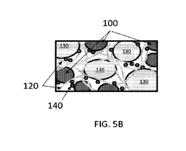
[10] FIGS. 5A and 5B are sectional, schematic views of a portion of an anode
electrode of
an embodiment in its as-fabricated state and after repeated charge-discharge
cycles,
respectively.
[11] FIGS. 6A, 6B and 6C are graphs showing capacity retention of Exemplary
and
Comparative half-cells.
DETAILED DESCRIPTION OF THE PREFERRED EMBODIMENTS
[12] The various embodiments will be described in detail with reference to the
accompanying drawings. Wherever possible, the same reference numbers will be
used
throughout the drawings to refer to the same or like parts. References made to
particular
examples and implementations are for illustrative purposes, and are not
intended to limit the
scope of the invention or the claims.
2
CA 03151456 2022-3-16
WO 2022/015803
PCT/US2021/041554
[13] It will be understood that when an element or layer is referred to as
being "on" or
"connected to" another element or layer, it can be directly on or directly
connected to the
other element or layer, or intervening elements or layers may be present In
contrast, when
an element is referred to as being "directly on" or "directly connected to"
another element or
layer, there are no intervening elements or layers present. It will be
understood that for the
purposes of this disclosure, "at least one of X, Y, and Z" can be construed as
X only, Y only,
Z only, or any combination of two or more items X, Y, and Z (e.g., XYZ, XYY,
YZ, ZZ)
[14] Where a range of values is provided, it is understood that each
intervening value, to
the tenth of the unit of the lower limit unless the context clearly dictates
otherwise, between
the upper and lower limit of that range and any other stated or intervening
value in that stated
range is encompassed within the invention. The upper and lower limits of these
smaller
ranges may independently be included in the smaller ranges is also encompassed
within the
invention, subject to any specifically excluded limit in the stated range.
Where the stated
range includes one or both of the limits, ranges excluding either or both of
those included
limits are also included in the invention. It will also be understood that the
term "about" may
refer to a minor measurement errors of, for example, +/- 5% to 10%.
[15] Words such as "thereafter," "then," "next," etc. are not necessarily
intended to limit
the order of the steps; these words may be used to guide the reader through
the description of
the methods. Further, any reference to claim elements in the singular, for
example, using the
articles "a," "an" or "the" is not to be construed as limiting the element to
the singular.
[16] An "electrode material" is defined as a material that may be configured
for use as an
electrode within an electrochemical cell, such as a lithium ion rechargeable
battery. An
"electrode" is defined as either an anode or a cathode of an electrochemical
cell. A
"composite electrode material" is also defined to include active material
particles combined
with one of particles, flakes, spheres, platelets, sheets, tubes, fibers, or
combinations thereof
and that are of an electrically conductive material The particles, flakes,
spheres, platelets,
sheets, tubes, fibers or combinations thereof may further be one of flat,
crumpled, wrinkled,
layered, woven, braided, or combinations thereof
[17] The electrically conductive material, may be selected from the group
consisting of an
electrically conductive carbon-based material, an electrically conductive
polymer, graphite, a
metallic powder, nickel, aluminum, titanium, stainless steel, and any
combination thereof,
The electrically conductive carbon-based material may further include one of
graphite,
3
CA 03151456 2022-3-16
WO 2022/015803
PCT/US2021/041554
graphene, diamond, pyrolytic graphite, carbon black, low defect turbostratic
carbon,
fullerenes, or combinations thereof An "electrode material mixture" is defined
as a
combination of materials such as: material particles (either electrochemically
active,
electrically conductive, composite or combinations thereof), a binder or
binders, a non-
crosslinking and/or a crosslinking polymer or polymers, which are mixed
together for use in
forming an electrode for an electrochemical cell. An "electrochemically active
material",
"electrode active material" or "active material" is defined herein as a
material that inserts and
releases ions such as ions in an electrolyte, to store and release an
electrical potential. The
term "inserts and releases" may be further understood as ions that intercalate
and
deintercalate, or lithiate and delithiate. The process of inserting and
releasing of ions is also
understood, therefore, to be intercalation and deintercalation, or lithiation
and delithiation.
An "active material" or an "electrochemically active material" or an "active
material
particle", therefore, is defined as a material or particle capable of
repeating ion intercalation
and deintercalation or lithium lithiation and delithiation.
[18] As defined herein a secondary electrochemical cell is an electrochemical
cell or
battery that is rechargeable. "Capacity" is defined herein as a measure of
charge stored by a
battery as determined by the mass of active material contained within the
battery,
representing the maximum amount of energy, in ampere-hours (Ah), which can be
extracted
from a battery at a rated voltage. Capacity may also be defined by the
equation: capacity =
energy/voltage or current (A) x time (h). "Energy" is mathematically defined
by the
equation: energy = capacity (Ah) x voltage (V). "Specific capacity" is defined
herein as the
amount of electric charge that can be delivered for a specified amount of time
per unit of
mass or unit of volume of active electrode material. Specific capacity may be
measured in
gravimetric units, for example, (Ah)/g or volumetric units, for example,
(Ah)/cc. Specific
capacity is defined by the mathematical equation: specific capacity (Ali/kg) =
capacity
(Ah)/mass (kg). "Rate capability" is the ability of an electrochemical cell to
receive or
deliver an amount of energy within a specified time period. Alternately, "rate
capability" is
the maximum continuous or pulsed energy a battery can provide per unit of
time.
[19] "C-rate" is defined herein as a measure of the rate at which a battery is
discharged
relative to its maximum nominal capacity. For example, a 1C current rate means
that the
discharge current will discharge the entire battery in 1 hour; a C/2 current
rate will
completely discharge the cell in 2 hours and a 2C rate in 0.5 hours. "Power"
is defined as the
4
CA 03151456 2022-3-16
WO 2022/015803
PCT/US2021/041554
time rate of energy transfer, measured in Watts (W). Power is the product of
the voltage (V)
across a battery or cell and the current (A) through the battery or cell. "C-
Rate" is
mathematically defined as C-Rate (inverse hours) = current (A)/capacity (Ah)
or C-Rate
(inverse hours) = 1/discharge time (h). Power is defined by the mathematical
equations:
power (W) = energy (Wh)/time (h) or power (W) = current (A) x voltage (V).
Coulombic
efficiency is the efficiency at which charge is transferred within an
electrochemical cell.
Coulombic efficiency is the ratio of the output of charge by a battery to the
input of charge.
[20] Considerable development in both commercial and academic settings has
been
focused on designing systems that minimize or accommodate total volume
swelling of alloy
particles and associated electrochemical losses. This has typically been
approached on two
fronts. At the particle level, designing particle architectures that confine
swelling to small
domains to prevent particle fracture and electrical disconnection, and at the
electrode level,
designing a polymer matrix and conductive network that can accommodate the
volume swell
of the lithium storing materials while retaining mechanical and electronic
integrity during
repeated charge / discharge operation of the Li-ion cell.
[21] A popular technique to stabilize the cycle life of alloy active anode
materials such as
silicon is through the mixture, encapsulation or other incorporation by
various carbon
materials to provide an electronically conducting surface and facilitate
general electronic
conduction throughout the electrode particle network. These include CVD
amorphous carbon
coatings, graphene wrappings, and physical mixing with graphite, conductive
carbons, and
carbon nanoplatelets. However, active materials may still swell due to their
rigid nature and
lack of long range order, and particles may still become isolated resulting in
storage capacity
loss and trapped lithium.
[22] Various embodiments of the present disclosure provide an anode material
for Li-ion
batteries that includes active material particles comprising an alkali metal
or an alkali earth
metal silicate and single-wall carbon nanotubes (SWCNTs) that provide long
range
conductivity in the active material particle network, enabling increased cycle
life stability
despite the inherent swelling associated with the lithium storing metal alloy
particles.
[23] SiO Materials
[24] Silicon and silicon alloys may significantly increase cell capacity when
incorporated
within an electrode of an electrochemical cell. Silicon and silicon alloys are
often
incorporated within an electrode comprising graphite, graphene, or other
carbon-based active
CA 03151456 2022-3-16
WO 2022/015803
PCT/US2021/041554
materials. Examples of electrodes comprising carbon-based materials and
silicon are
provided in U.S. patents 8,551,650, 8,778,538, and 9,728,773 to Kung et al.,
and U.S. patents
10,135,059 and 10,135,063 to Huang et al., all the contents of which are fully
incorporated
herein by reference.
[25] Herein, "SiO" materials may refer to silicon and oxygen-containing
materials. SiO
materials are of interest for use in anode electrodes of lithium-ion
batteries, due to having
high theoretical energy and power densities. However, the utilization of
current commercial
SiO materials has been limited due to SiO materials having a low 1S1 cycle
efficiency and a
high irreversibility. This low 1 cycle efficiency is due to high irreversible
Li reaction with
the SiO matrix.
[26] In order to decrease the irreversible Lit reaction with silicon oxide,
various
embodiments include metalized silicon oxide materials (M-SiO). Herein, M-SiO
materials
may refer to active materials that are directly reacted with metal-containing
precursors, such
as alkali and/or alkali earth containing precursors, such as for example,
lithium-containing
precursors and/or magnesium-containing precursors, to form metalized silicon
and oxygen-
containing phases, prior to being utilized in a battery as an active material
and/or undergoing
charge and discharge reactions. In one embodiment, all or some of the
metalizing metal may
remain in the active material and does not intercalate (i.e., does not insert)
or de-intercalate
during battery charging and discharging. However, in some embodiments, M-SiO
materials
may include SiO materials that are metalized to include other suitable alkali
and/or alkali
earth metals, such as sodium, potassium, calcium, or the like. For example, in
some
embodiments, M-SiO materials may be metalized to include magnesium, lithium,
sodium,
potassium, calcium, or any combinations thereof Preferably, M-SiO materials
may refer to
lithium-metalized SiO (LM-SiO) materials and/or Mg-metalized SiO (MM-SiO)
materials.
[27] Electrode materials including M-SiO active materials have been found to
provide
increased 1s1 cycle efficiency (FCE), as compared to non-metalized SiO
materials.
Unfortunately, M-SiO materials have been found to suffer from severe
electrical
disconnection and rapid capacity loss, often leading to more than 90% capacity
fade within
20 cycles. Coating M-SiO materials with carbon and/or other materials, and/or
blending M-
SiO materials with graphite have been found to slightly reduce the electrical
disconnection
and capacity loss of active materials, delaying the over 50% capacity fade to -
---50 cycles,
6
CA 03151456 2022-3-16
WO 2022/015803
PCT/US2021/041554
which is still highly unsatisfactory cycling stability for commercial
applications. Overall,
current M-SiO materials do not exhibit electrical stability sufficient for
commercialization.
[28] FIG. 1A is a scanning electron microscope (SEM) image of an active
material particle
100, according to various embodiments of the present disclosure, FIGS. 1B-1D
are a
sectional diagrams of core particles 102A-102C that may be included in an
active material
particle 100 of FIG. 1A. Referring to FIGS. IA and 1B, the active material
particles 100
include a core particle 102 comprising an electrochemically active material,
and a graphene-
containing coating 110 that is coated on and/or encapsulates, the core
particle 102.
[29] In preferred embodiments, the core particle 102 comprises an M-SiO
material. As
such, the active material particles 100 are described below with respect to
core panicles 102
that comprise an M-SiO material.
[30] The active material particles 100 and/or core particles 102 may have an
average
particle size that ranges from about 1 gm to about 20 gm, such as from about 2
gm to about
15 gm, from about 3 gm to about 10 pm, from about 3 gm to about 7 gm, or about
5 pm.
The core particles 102 may include M-SiO materials that include metalized
silicon species
and silicon (e.g., crystalline and/or amorphous silicon). The metalized
silicon species may
include metalized silicides and metalized silicates. In some embodiments, the
M-SiO
materials may also include silicon oxide (SiO., wherein x ranges from 0.8 to
1.2, such as
from 0.9 to 1.1). In various embodiments, the M-SiO materials may include
lithiated silicon
species. Herein, "lithiated silicon species" may include lithium silicides
(Li.Si, 0<x<4.4),
and/or one or more lithium silicates (Li2Si205, Li2SiO3, and/or Li4SiO4,
etc.).
[31] Referring to FIG. 1B, in some embodiments, the active material particles
100 may
include heterogeneous core particles 102A that include an M-SiO material that
includes
multiple silicon-containing material phases 104, 106, 108. For example, the
phases 104, 106,
108 may independently comprise crystalline silicon, silicon oxide (e.g., SiOx,
wherein x
ranges from 0.8 to 1.2, such as from 0.9 to 1.1), and/or lithiated silicon
species. However, in
some embodiments the core particles 102 may be substantially homogeneous
particles that
lack distinct phases, but include silicon, oxygen and lithium.
[32] Referring to FIG. 1C, in some embodiments, the active material particles
100 may
comprise core particles 102B that include a primary phase 120, in which
crystalline silicon
domains 122 are dispersed as a secondary phase. For example, the primary phase
120 may
include titillated silicon species such as lithium silicate species, and in
particular, Li2Si205.
7
CA 03151456 2022-3-16
WO 2022/015803
PCT/US2021/041554
In other embodiments, the primary phase 120 may comprise magnesium-metalized
silicon
species, such as magnesium silicate species, and in particular MgSiO3,
Mg2S104,
combinations thereof, or the like. The crystalline silicon domains 122 may
comprise
crystalline silicon nanoparticles having a particle size of less than 100 nm.
For example, the
crystalline silicon domains 122 may have an average particle size ranging from
about 3 nm to
about 60 nm. In one embodiment, a majority of the crystalline silicon domains
122 may have
an average particle size ranging from about 5 nm to about 10 nm, and a
remainder of the
crystalline silicon domains 122 may have an average particle size from about
10 nm to about
50 nm.
[331 Referring to FIG. 1D, in some embodiments the active material particles
100 may
comprise core particles 102C that include a primary phase 120 comprising an M-
SiO
material, and crystalline silicon domains 122 and SiO. domains 124 (e.g.,
SiO., wherein x
ranges from 0.8 to 1.2, such as from 0.9 to 1.1) dispersed in the primary
phase 120 as
secondary phases. For example, the primary phase 120 may include lithiated
silicon species
such as lithium silicate species, and in particular, Li2Si205, the crystalline
silicon domains
122 may comprise crystalline silicon nanoparticles, and the Si . domains 124
may include
SiOx phases and/or nanoparticles. The crystalline silicon domains 122 and the
SiO. domains
124 may have a particle size of less than about 100 nm. For example, the
crystalline silicon
domains 122 and the SiOx domains 124 may have an average particle size ranging
from about
3 nm to about 60 nm, such as from about 5 nm to about 50 nm.
II
In various embodiments, the core
particles 102 may represent from about 80 wt% to
about 99.5 wt%, such as from about 90 wt% to about 99 wt%, including about 90
wt% to 95
wt% of the total weight of the active material particles 100. In some
embodiments the M-SiO
material may include from about 40 at% to about 5 at%, such as from 20 at% to
about 10
at%, or about 15 at% of lithiated silicon species. In some embodiments the M-
SiO material
of the core particles 102A may include from about 60 at% to about 95 ar/o,
such as from
about 80 at% to about 90 at%, or about 85 at% silicon and Si,. The M-SiO
material of the
core particles 102 may have a silicon to oxygen atomic weight ratio ranging
from about
L25:1 to about 1:1.25, such as from about 1.1:1 to about 1:1.1, or of about
1:1. In some
embodiments, the M-SiO material of the core particles 102 may comprise
approximately
equal atomic amounts of crystalline silicon and SiO,
8
CA 03151456 2022-3-16
WO 2022/015803
PCT/US2021/041554
[35] During an initial charging reaction and/or subsequent charging reactions,
the
composition of the M-SiO material of the core particles 102A may change due to
lithiation
and/or other reactions. For example, Si and SiO, may be lithiated to form
Li,,Si domains. In
addition, some SiOx may form inactive species, such as lithium silicates and
Li2O.
[36] In various embodiments, the coating 110 may be in the form of a shell
that completely
encapsulates the core particles 102, as shown in FIGS. 1B ¨ 1D However, in
some
embodiments, the coating 110 may only partially encapsulate some or all of the
core particles
102. In some embodiments, the coating 110 may represent, based on the total
weight of an
active material particle, from about 0.5 wt% to about 20 wt%, such as from
about 1 wt% to
about 10 wt%, or from about 5 wt% to about 10 wt%, of the total weight of the
active
material particle 100.
[37] Turbostratic Carbon
ps1 In some embodiments, the coating 110 may include a
flexible, highly-conductive
graphene material, such as graphene, graphene oxide, partially reduced
graphene oxide, or
combinations thereof. For example, the coating 110 may preferably comprise a
flexible,
highly conductive graphene material having low-defect turbostratic
characteristics, which
may be referred to as turbostratic carbon. The low-defect turbostratic carbon
may be in the
form of platelets comprising from one to about 10 layers of a graphene
material, such as
graphene, graphene oxide, or reduced graphene oxide. In some embodiments, the
low-defect
turbostratic carbon may comprise at least 90 wt%, such as from about 90 wt% to
about 100
wt% graphene. The graphene material may further comprise a powder, particles,
mono-layer
sheets, multi-layer sheets, flakes, platelets, ribbons, quantum dots, tubes,
fullerenes (hollow
graphenic spheres) or combinations thereof
I1 The turbostratic carbon may be in the form of sheets
or platelets that partially overlap
to simulate larger size single sheet structures. In some embodiments the
platelets have more
than one or more layers of a graphene-based material. In some embodiments, the
platelets
may have sheet size may be on average < 15 Rm. In some embodiments, the
platelets may
have sheet size may be on average < 1 p.m. In some embodiments, the
turbostratic carbon-
based material platelets may have low thickness. In some embodiments, a low
thickness of
the turbostratic carbon-based material platelets may be on average < 1 tim. In
some
embodiments, a low thickness of the turbostratic carbon-based material
platelets may be on
averages 100 nm.
9
CA 03151456 2022-3-16
WO 2022/015803
PCT/US2021/041554
[40] In various embodiments, the coating 110 may be in the form of a shell
that completely
encapsulates the particle 100, as shown in FIG. 1B. However, in some
embodiments, the
coating 110 may partially encapsulate some or all of the active material
particles 100. In
some embodiments, the coating 110 may represent from about 0.5 wt% to about 20
wrA,
such as from about 1 wt% to about 10 wt%, or from about 5 wt% to about 10 wrA,
of the
total weight of the particles 100 and the coating 110.
[41] The coating 110 may ensure that the core particles 102 are
homogenously/uniformly
cycled (movement of electrons and Li-ions in and out of the structure) in all
three
dimensions, due to its conductive nature, thereby minimizing the stresses
exerted on and by
the core particle and minimizing particle fracture. Additionally, in the event
that a particle
100 does fracture, the flexible coating 110 may operate to electrically
connect the fractured
silicon oxide material and maintain the overall integrity of the particle 100,
thereby leading to
significantly improved electrochemical performance.
[42] FIGS. 2A, 2B and 2C illustrate Raman spectra for graphite and various
graphene-
based materials. It has been well established that graphite and grapheme
materials have
characteristic peaks at approximately 1340 cm', 1584 cm"' and 2700 cm"'. The
peak at 1340
cnci is shown in FIG. 2C, and is characterized as the D band. The peak at 1584
cm' is
shown in the spectra of FIGS. 2A and 2C, and is characterized as the G band,
which results
from the vibrational mode represented by the C=C bond stretching of all pairs
of sp2
hybridized carbon atoms. The D band originates from a hybridized vibrational
mode
associated with graphene edges and it indicates the presence of defects or
broken symmetry
in the graphene structure. The peak at 2700 cm"' is shown in FIG. 2B, and is
characterized as
the 2D band, which results from a double resonance process due to interactions
between
stacked graphene layers. The emergence of a double peak at the 2D wavenumber
breaks the
symmetry of the peak, and is indicative of AB stacking order between graphene
planes in
graphite and graphite derivatives such as nanoplatelets. The 2D1 peak shown in
FIG. 1B
becomes suppressed when the AB stacking order in turbostratic multilayer
graphene particles
is disrupted. The positions of the G and 2D bands are used to determine the
number of layers
in a material system. Hence, Raman spectroscopy provides the scientific
clarity and
definition for electrochemical cell carbon material additives, providing a
fingerprint for
correct selection as additives for active material electrode compositions. As
will be shown,
the present definition provides that fingerprint for the low-defect
turbostratic carbon of the
CA 03151456 2022-3-16
WO 2022/015803
PCT/US2021/041554
present application. It is this low-defect turbostratic carbon when used as an
additive to an
electrochemical cell electrode active material mixture that provides superior
electrochemical
cell performance.
[43] FIG. 3 provides the ID/1.6 ratio of carbon additives typically used in
prior art electrode
active material mixtures (i.e., reduced graphene oxide or amorphous carbon)
compared with
the low-defect turbostratic carbon of the present application.
[44] Reduced graphene oxide (rGO) is a carbon variant that is often referred
to as graphene
in the industry, however, is unique in final structure and manufacturing
process. Graphene
oxide is typically manufactured first using a modified Hummers method wherein
a graphite
material is oxidized and exfoliated into single layers or platelets comprising
a few layers of
carbon that may comprise various functional groups, including, but not limited
to, hydroxyls,
epoxides, carbonyls, and carboxyls. These functional groups are then removed
through
chemical or thermal treatments that convert the insulating graphene oxide into
conductive
reduced graphene oxide. The reduced graphene oxide is similar to graphene in
that it consists
of single layers of carbon atom lattices, but differs in that it has mixed sp2
and sp3
hybridization, residual functional groups and often increased defect density
resultant from the
manufacturing and reduction processes. Reduced graphene oxide is shown in the
first bar of
FIG. 3 and has an ID/IG ratio of 0.9.
[45] Amorphous carbon is often used as an additive or surface coating for both
electrochemical cell anode and cathode material mixtures to enhance electrode
conductivity.
Typically, amorphous carbons are produced using a chemical vapor deposition
(CVD)
process wherein a hydrocarbon feedstock gas is flowed into a sealed vessel and
carbonized at
elevated temperatures onto the surface of a desired powder material. This
thermal
decomposition process can provide thin amorphous carbon coatings, on the order
of a few
nanometers thick, which lack any sp2 hybridization as found in crystalline
graphene-based
materials. Amorphous carbon is shown in the third bar of FIG. 3 and has an
ID/IG ratio >1.2.
[46] Low-defect turbostratic carbon, also referred to as graphene, comprises
unique
characteristics resultant from its manufacturing processing. One common method
of
producing this material is through a plasma based CVD process wherein a
hydrocarbon
feedstock gas is fed through an inert gas plasma in the presence of a catalyst
that can nucleate
graphene-like carbon structures. By controlling the production parameters,
carbon materials
having a few layers and absent any AB stacking order between lattices can be
produced.
11
CA 03151456 2022-3-16
WO 2022/015803
PCT/US2021/041554
These carbon materials are typically highly ordered sp2 carbon lattices with
low-defect
density.
[47] The low-defect turbostratic carbon of the present disclosure is shown in
the center
second bar of FIG. 3. The Raman spectrum of the low-defect turbostratic carbon
additive of
the present application is derived from the intensity ratio of the D band and
the G band (ID/16)
and the intensity ratio of the 2D band and the G band (linfl6). The In, I2D,
and IG are
represented by their respective integrated intensities. A low ID/IG ratio
indicates a low-defect
material. The low-defect turbostratic carbon material of the present invention
has an ID/16
ratio of greater than zero and less than or equal to about 0.8, as determined
by Raman
spectroscopy with IG at wavenumber in a range between 1580 and 1600 cm4, ID at
wavenumber in a range between 1330 and 1360 cm-1, and being measured using an
incident
laser wavelength of 532 nm. Additionally, the low-defect turbostratic carbon
material of the
present disclosure exhibits an I2D/IG ratio of about 0.4 or more. As reference
regarding the
12D/IG ratio, an '2D/IC) ratio of approximately 2 is typically associated with
single layer
graphene. '2D/IC) ratios of less than about 0.4 is usually associated with
bulk graphite
consisting of a multitude of AB stacked graphene layers. Hence, the I.2D/IG
ratio of about 0.4
or more, for the low-defect turbostratic carbon material of the present
disclosure, indicates a
low layer count of < 10. The low-defect turbostratic carbon material of low
layer count
further lacks an AB stacking order between graphene layers (i.e.,
turbostratic). The
turbostratic nature or lack of AB stacking of these graphene planes is
indicated by the
symmetry of the 12D peak. It is the symmetry of the 2D peak that distinguishes
a turbostratic
graphene layered material from an AB stacked graphene layered material, and is
indicative of
rotational stacking disorder versus a layered stacking order.
[48] Carbon materials with high AB stacking order will still exhibit 2D peaks,
however,
these 2D peaks exhibit a doublet that breaks the symmetry of the peak. This
break in
symmetry is exhibited in both AB stacked graphene of a few layers or graphite
of many
layers. Thus, the 2D peak, which is a very strong indicator of the presence of
stacking order
regardless of the number of graphene layers present in the material, is of
significance when
selecting a graphene or graphene-based additive. It is the rotational disorder
of the stacking
in the low-defect turbostratic carbon of the present disclosure that
distinguishes itself from all
the other graphene or graphene-based additives used to date, as the rotational
disorder of the
low-defect turbostratic carbon stacking of the present application is what
offers flexibility to
12
CA 03151456 2022-3-16
WO 2022/015803
PCT/US2021/041554
the carbon-based particles of the present application, which therein enables
the ability of
these carbon-based particles to provide and preserve contact with the active
core particle of
the composite particles comprising the electrode of the electrochemical cell.
The result is an
electrochemical cell having increased cycle life, better cycle life stability,
enhanced energy
density, and superior high rate performance.
[49] FIGS. 4A-4C illustrate Raman spectra for active material mixtures
comprising SiO
particles encapsulated by or coated with a carbon material. FIG. 4A is a graph
of the Raman
spectra for an active material mixture comprising SiO core particles coated
with an
amorphous carbon material. FIG. 4E1 is a graph of the Raman spectra for an
active material
mixture comprising SiO core particles encapsulated by rGO. FIG. 4C is a graph
showing the
Raman spectra for an active material mixture comprising core particles
encapsulated by a
low-defect turbostratic carbon. Each spectra is different because of varying
layer thickness
(size, shape and position of 2D peak around wavelength 2700 cm4) and disorder
(size of D
peak around wavelength 1340 cm').
[SO] Raman analysis sample preparation involved taking small aliquots of
powders such as
active material powders, composite material powders, carbon material powder,
and placing
these powders individually into a clean glass vial. The sample powder is
rinsed with
methanol. The powder/methanol solutions are then vortexed briefly and
sonicated for
approximately 10 minutes. The suspension is then transferred to a microscope
slide with a
micropipette. The slides are then allowed to air dry completely before
conducting the
analysis.
[51] The Raman spectroscopy analysis of the present application is conducted
using
confocal Raman spectroscopy on a Bruker Senterra Raman System under the
following test
conditions: 532 nm laser, 0.02mW, SOX objective lens, 90 second integration
time, 3 co-
additions (3 Raman spectroscopy sample runs) using a 50 x 1000jtm aperture and
a 9-18 cm-L
resolution. As a point of reference, the D band is not active in the Raman
scattering of
perfect crystals. The D band becomes Raman active in defective graphitic
materials due to
defect-induced double resonance Raman scattering processes involving the itrit
electron
transitions. The intensity of the D band relative to the G band increases with
the amount of
disorder. The intensity ID/IC ratio can thereby be used to characterize a
graphene material.
[52] The D and G bands of the amorphous carbon shown in FIG. 4A are both of
higher
intensity than either the reduced graphene oxide (rGO) D and G bands of FIG.
4B or the
13
CA 03151456 2022-3-16
WO 2022/015803
PCT/US2021/041554
turbostratic carbon D and G bands of FIG. 4C. The amorphous carbon also
exhibits a
substantially higher ID/IG ratio (1.25) than do rGO and turbostratic carbon.
The suppressed
intensity of the amorphous carbon G band compared to that of its D band
reflects the lack of
crystallinity (also known as its graphitic nature) within its carbon
structure. The D peak
intensity being higher than the G peak intensity is caused by the high amount
of defects in the
amorphous carbon network. Hence, the amorphous carbon spectra exhibits low
crystallinity
and a much higher degree of disorder in its graphitic network compared with
more crystalline
carbons, such as graphene, graphene oxide, and rGO. Moreover, the higher
intensity of the
rGO D peak compared with its G peak, and its higher ID/IG ratio (almost 2X)
compared to the
turbostratic carbon D and G peak intensities and ID/IG ratio indicates the rGO
to have more
defects than the turbostratic carbon of the present application.
[53] Table 1 below provides the detail for the Raman spectra of FIGS. 4A-
4C.
Table 1
rGO D G
2D ID/IC 12D1'G
Cm-I 1346.98 1597.82
Intensity 9115.5 10033.3
.91
Low Defect
Turbostratic D G
2D Ulu 12WIG
Carbon
Cmd 1346.92 158132
2691.9
Intensity 2915.3 5849.98
6009.4 0.5 1,03
Amorphous
2D
ID/IC 12p/1G
Carbon
1344.93 1589.40
2695.4
Intensity 6194.8 4908.2
5238.5 1.25 1.07
[54] Careful inspection of these spectra show that when disorder increases,
the D band
broadens and the relative intensity of the band changes. For the amorphous
carbon coated
sample, the high intensity (6194.8) and broad D peak indicates a high amount
of defects. The
G peak being lower in intensity (4908.2) then the D peak (6194.8) indicates a
lack of
14
CA 03151456 2022-3-16
WO 2022/015803
PCT/US2021/041554
crystallinity. The D peak intensity (9115.5) and G peak intensity (10033.3) of
the rGO
encapsulated sample are fairly alike. Noticeable, however, is that the peak
intensity
(9115.5) of the rGO sample is substantially higher than the D peak intensity
(2915.3) of the
turbostratic carbon sample indicating that the rGO sample has substantially
higher defect
density than does the turbostratic carbon sample. Also noticeable is that the
G band for the
amorphous carbon and the rGO samples are shifted to the right of wavelength
1584 cm-l- to
wavelength 1589.4 cm' and 1597.82 cm' respectively, whereas the G band for the
turbostratic carbon sample lies slightly to the left of wavelength of 1584 cm'
at 1581.32 cm-1.
Of significance is that, unlike the amorphous carbon and the rGO samples, the
turbostratic
carbon (in this case, graphene sample) does not display much, if any, shift in
position,
reflecting low-defects Therein, thus, the turbostratic carbon sample most
nearly resembles an
almost 'perfect' turbostratic carbon material.
[55] Electrode Materials
[56] Various embodiments of the present disclosure provide electrode materials
for Li-ion
batteries, and in particular, anode electrode compositions. As shown in FIG.
5A, the
electrode material may include an active material, a binder (not shown), and
single-wall
carbon nanotubes (SWCNTs) 120. The active material may include the above
described
active material particles 100 and optionally additional graphite particles
130. In some
embodiments, the electrode materials may optionally include a conductive
additive, such as
carbon black particles 140. The active material particles 100 and the graphite
particles 130
may be mixed with each other. The carbon black particles 140 may be smaller
(i.e., have a
smaller diameter) than the active material particles 100 and the graphite
particles 130, and
may be located between and/or on surfaces of the active material particles 100
and/or the
graphite particles 130. The SWCNTs 120 may extend between the mixture of
active material
particles 100 and the graphite particles 130 and provide long range
conductivity across
multiple active particles (100, 130).
1571 As shown in FIG. 5B, after numerous charge and discharge cycles, the
silicon oxide
particles 100 and the graphite particles 130 may swell and push away from each
other.
However, the SWCNTs 120, due to their large length and high aspect ratio,
still contact and
electrically connect multiple active material particles 100 and graphite
particles 130. Thus,
the SWCNTs 120 are believed to provide a percolating network (e.g., web or
mesh above a
CA 03151456 2022-3-16
WO 2022/015803
PCT/US2021/041554
percolation threshold) of conductive links between the active particles which
provides
sufficient conductivity to the anode electrode.
[58] The electrode materials may include at least 80 wt% of the active
material, such as at
least 90 wt%, at least 94 wt%, such as 90 to 96.5 wt% of the active material.
The active
material may include a mixture of active material particles 100 and optionally
graphite
particles 130. For example, the active material may include from about 5 wt%
to about 50
wt%, such as from about 10 wt% to about 30 wt%, from about 15 wt% to about 25
wt% M-
SiO, and from about 95 wt% to about 50 wt%, such as from about 90 wt% to about
70 wt%,
from about 85 wt% to about 75 wt% graphite. In some preferred embodiments, the
active
material may include less than 50 wt% M-SiO and more than 50 wt% graphite.
Thus, the
active material may include more graphite particles 130 than active material
particles 100 by
weight.
[59] The active material particles 100 may include silicon and metal silicate
phases and
optionally silicon oxide phases described above. The active material particles
100 may
include the optional carbon coating 110, or the carbon coating 110 may be
omitted.
[60] The active material particles 100 may have an average particle size that
ranges from
about 1 gm to about 20 gm, such as from about 1 gm to about 10 gm, from about
3 gm to
about 7 gm, or about 5 pm. The active material particles 100 may have a
surface area that
ranges from about 0.5 m2/g to about 30 m2/g, such as from about 1 m2/g to
about 20 m2/g,
including from about 5 m2/g to about 15 m2/g.
[61] The graphite may include graphite particles 130 of synthetic or natural
origin. The
graphite may have an average particle size ranging from about 2 pm to about 30
pm, such as
from about 10 gm to about 20 pm, including from about 12 gm to about 18 gm. In
one
embodiment, the average particle size of the graphite particles 130 may be
larger than the
average particle size of the silicon oxide particles 100. The graphite
particles 130 may have a
surface area that ranges from about 0.5 m2/g to about 2.5 m2/g, such as from
about 1 ne/g to
about 2 m2/g. The graphite particles 130 may be larger than the silicon oxide
particles 110.
[62] The electrode material may include any suitable electrode material binder
(not shown
in FIGS. 5A and 5B for clarity). For example, the electrode material may
include a polymer
binder such as polyvinylidene difluoride (PVDF), Na-carboxymethyl cellulose
(CMC),
styrene butadiene rubber (SBR), polyacrylic acid (PAA), lithium polyacrylate
(LiPAA), a
combination thereof, or the like. In some embodiments, the binder may include
a
16
CA 03151456 2022-3-16
WO 2022/015803
PCT/US2021/041554
combination of the CMC and the SBR, where the CMC has a molecular weight from
250 to
850 g/mol and a degree of substitution from 0.65 to 0.9.
[63] In various embodiments, the electrode material may include from about 1
wt% to
about 5 wt%, or from about 2 wt% to about 3 wt% binder.
[64] The SWCNTs 120 may have an average length of greater than about 1 pm. For
example, the SWCNTs may have an average length ranging from about 1 pim to
about 500
gm, such as from about 1 gm to about 10 gm. The SWCNTs may have an average
diameter
ranging from about 0.5 nm to about 2.5 nm, such as from about 1 nm to about 2
nm.
[65] The SWCNTs 120 may have an IC/ID ratio or greater than about 5, such as
greater
than about 6 or greater than about 10, as determined by Raman spectroscopy,
with IG being
associated with the Raman intensity at wavenumber 1580¨ 1600 cm-1, and ID
being
associated with the Raman intensity at wavenumber 1330¨ 1360 cm-1, as measured
using an
incident laser wavelength of 633 nm.
1661 In various embodiments, the electrode material may include from about
0.05 wt% to
about 1 wt%, such as from about 0.075 wt% to about 0.9 wt%, from about 0.08
wt% to about
0.25 wt%, or about 0.1 wt% SWCTNs.
[67] The conductive additive (i.e., conductive agent) may include carbon black
(e.g.,
KETJENBLACK or Super-P carbon black), low defect turbostratic carbon,
acetylene black,
channel black, furnace black, lamp black, thermal black or combinations
thereof. The
conductive additive may optionally include metal powder, fluorocarbon powder,
aluminum
powder, nickel powder; nickel flakes, conductive whiskers, zinc oxide
whiskers, potassium
titanate whiskers, conductive metal oxides, titanium oxide, conductive organic
compounds,
conductive polyphenylene derivatives, conductive polymers, or combinations
thereof.
[68] In various embodiments, the electrode material may include from 0 to
about 5 wt%,
such as from about 0.1 wt% to about 5 wt%, including from about 0.25 wt% to
about 3 wr/o,
from about 0.5 wt% to about 1.5 wt%, or about 1 wt% conductive additive (i e.,
conductive
agent) selected from carbon black, an electrically conductive polymer, a
metallic powder, or
any combination thereof. In some embodiments, the conductive additive may
preferably
include carbon black.
1691 Anode Formation
[70] According to various embodiments, an anode may be formed using any
suitable
method known to one or skill in the art. For example, active material
particles 100 described
17
CA 03151456 2022-3-16
WO 2022/015803
PCT/US2021/041554
above may be mixed with graphite particles 130 to form an active material. In
one
embodiment, the active material may include less than 50 wt% M-SiO and more
than 50 wt%
graphite. The active material may be mixed with the SWCNTs, binder and the
optional
conductive additives to form a solids component. In some embodiments, the
active material
particles may be coated with turbostratic carbon coating 110 using, for
example, a spray
drying process, prior to forming the active material. Alternatively, the
coating 110 may be
omitted.
1711 The solids component may be mixed with a polar solvent such as water or N-
Methy1-
2-pyrrolidone (NMP), at a solids loading between about 20-60 wt%, to form an
electrode
slurry. For example, the mixing may include using a planetary mixer and high
shear
dispersion blade, under vacuum.
[72] The electrode slurry may then be coated onto a metal substrate, such as a
copper or
stainless steel substrate, at an appropriate mass loading to balance the
lithium capacity of the
anode with that of a selected cathode. Coating can be conducted using a
variety of apparatus
such as doctor blades, comma coaters, gravure coaters, and slot die coaters.
[73] After coating, the slurry may be dried to form an anode. For example, the
slurry may
be dried under forced air, at a temperature ranging from room temperature to
about 120 C.
The dried slurry may be pressed to reduce the internal porosity, and the
electrode may be cut
to a desired geometry. Typical anode pressed densities can range from about
1.0 g/cc to
about 1.7 g/cc depending on the composition of the electrode and the target
application.
Cathode pressed densities may range from about 2.7 to about 4.7 g/cc.
[74] In some embodiments, the active material particles may be coated with
turbostratic
carbon prior to forming the active material. For example, a mixture of active
material
particles, turbostratic carbon and a solvent may be spray dried, to form a
powder, and the
powder may then be heat-treated in an inert atmosphere, such as argon gas, to
carbonize any
remaining surfactant or dispersant. In other embodiments, the active material
particles may
be coated with turbostratic carbon using a binder and a mechano-fusion
process.
[75] Electrochemical Cell Assembly
[76] Construction of an electrochemical cell involves the pairing of a coated
anode
substrate and a coated cathode substrate that are electronically isolated from
each other by a
polymer and/or a ceramic electrically insulating separator. The electrode
assembly is
hermetically sealed in a housing, which may be of various structures, such as
but not limited
18
CA 03151456 2022-3-16
WO 2022/015803
PCT/US2021/041554
to a coin cell, a pouch cell, or a can cell, and contains a nonaqueous,
ionically conductive
electrolyte operatively associated with the anode and the cathode. The
electrolyte is
comprised of an inorganic salt dissolved in a nonaqueous solvent and more
preferably an
alkali metal salt dissolved in a mixture of low viscosity solvents including
organic esters,
ethers and dialkyl carbonates and high conductivity solvents including cyclic
carbonates,
cyclic esters and cyclic amides. A non-limiting example of an electrolyte may
include a
lithium hexafluorophosphate (LiPF6) or lithium bis(fluorosulfonyl)imide
(LiFSi) salt in an
organic solvent comprising one of: ethylene carbonate (EC), diethyl carbonate
(DEC),
dimethyl carbonate (DMC), fluoroethylene carbonate (FEC) or combinations
thereof.
[77] Additional solvents useful with the embodiment of the present invention
include
dialkyl carbonates such as tetrahydrofuran (THF), methyl acetate (MA),
diglyme, trigylme,
tetragylme, 1,2-dimethoxyethane (DME), 1,2-diethoxyethane (DEE), 1-ethoxy, 2-
methoxyethane (EME), ethyl methyl carbonate, methyl propyl carbonate, ethyl
propyl
carbonate, dipropyl carbonate, and combinations thereof. High permittivity
solvents that may
also be useful include cyclic carbonates, cyclic esters and cyclic amides such
as propylene
carbonate (PC), butylene carbonate, acetonitrile, dimethyl sulfoxide, dimethyl
formamide,
dimethyl acetamide, gamma-valerolactone, gamma-butyrolactone (GBL), N-methy1-2-
pyrrolidone (NMP), and combinations thereof.
[78] The electrolyte may also include one or more additives, such as vinylene
carbonate
(VC), 1,3-propane sulfone (PS), prop-1-ene-1,3-sultone (PES), Flouroethylene
carbonate
(FEC), and/or propylene carbonate (PC).The electrolyte serves as a medium for
migration of
lithium ions between the anode and the cathode during electrochemical
reactions of the cell,
particularly during discharge and re-charge of the cell. The electrochemical
cell may also
have positive and negative terminal and/or contact structures.
[79] Experimental Examples
[80] The following examples relate to anode formed using electrode materials
of various
embodiments of the present disclosure and comparative electrode materials, and
are given by
way of illustration and not by way of limitation. In the examples, % is
percent by weight, g is
gram, CE is coulombic efficiency, and mAh/g is capacity.
[81] Exemplary Cells 1-3 (El, E2, E3)
[82] The active material, SWCNTs, a conductive agent (carbon black), and a
binder
(CMC/SBR) were mixed to form a solids component. The solids component was
mixed with
19
CA 03151456 2022-3-16
WO 2022/015803
PCT/US2021/041554
a polar solvent (water or NMP), at a solids loading of between 20 wt% and 60
wt%, in a
planetary mixer having a high shear dispersion blade, under vacuum, to form
electrode
material slurries.
[83] The electrode material slurries were coated on copper current collectors
at an
appropriate mass loading to balance the lithium capacity of the anode with
that of a selected
cathode, dried, and pressed to form anodes. The anodes were assembled into
half-cells
(excess counter electrode material = lithium metal) and electrolyte was
provided into each of
the half-cells, to form Exemplary Cells 1-1 The anodes of Exemplary Cells 1-3
each
included 96 wt% active material, 0.1 wt% SWCNTs, 0.9 wt% carbon black, and 3
wt%
CMC/SBR binder.
[84] The anode of Exemplary Cell 1 included 20 wt% LM-SiO, and 76 wt%
graphite. The
anode of Exemplary Cell 2 included 30 wt% LM-SiO, and 66 wt% graphite. The
anode of
Exemplary Cell 3 included 30 wt% unmetallized SiO and 66 wt% graphite.
1851 Comparative Cells 1-4 (Cl, C2, C3, C4)
[86] Comparative Cells 1-4 were formed in the same manner as Exemplary Cells 1-
3. The
anode of Comparative Cell 1 included 20 wt% LM-SiO, 76 wt% graphite, 1 wt%
carbon
black, and did not include CNTs. The anode of Comparative Cell 2 included 30
wt% LM-
SiO, 66 wt% graphite, 0.9 wt% carbon black, and 0.1 wt% multi-walled carbon
nanotubes
(MWCNTs).
[87] The anode of Comparative Cell 3 included 30 wt% LM-SiO, 66 wt% graphite,
1 wr/o
carbon black, and did not include CNTs. The anode of Comparative Cell 4
included 30 wt%
unmetallized SiO, 66 wt% graphite, 1 wt% carbon black, and did not include
CNTs.
[88] The following Table 2 shows a half cell cycling protocol applied to the
Exemplary
and Comparative cells.
CA 03151456 2022-3-16
WO 2022/015803
PCT/US2021/041554
Table 2
Half Cell Cycling Protocol
Voltage Window
0.02¨ 1.5V
Formation 0.05C
Lithiation I 0.05C Delithiation
0.1C Lithiation I 0.1C Delithiation
0.5C Lithiation I 0.5C Delithiation
0.5C Lithiation I 1C Delithiation
0.5C Lithiation I 2C Delithiation
Cycling
0.5C Lithiation I 0.5C Delithiation
Rest
15 minutes between every charge
/ discharge step
[89] FIG. 6A is a graph showing the specific capacity retention of Exemplary
Cell 1 and
Comparative Cell 1, during cycling. As can be seen in FIG. 6A, Exemplary Cell
1, which
included SWCNTs, had excellent capacity retention for 100 cycles. In contrast,
Comparative
Cell 1, which did not include SWCNTs, lost more than 50% of its initial
capacity in fewer
than 20 cycles.
[90] FIG. 6B is a graph showing the specific capacity retention of Exemplary
Cell 2 and
Comparative Cells 2 and 3, during cycling. As can be seen in FIG. 6B,
Exemplary Cell 2,
which included SWCNTs, had excellent capacity retention. In contrast,
Comparative Cells 2
and 3, which respectively included MVVCNTs or did not include CNTs, exhibited
a greater
than 50% capacity loss in fewer than 10 cycles.
1911 FIG. 6C is a graph showing the specific capacity retention of Exemplary
Cell 3 and
Comparative Cell 4, during cycling. As can be seen in FIG. 6C, Exemplary Cell
4, which
included SWCNTs and unmetallized SiO, rather than LM-SiO, showed excellent
capacity
21
CA 03151456 2022-3-16
WO 2022/015803
PCT/US2021/041554
retention. In contrast, Comparative Cell 4, which included unmetallized SiO
and no CNTs
exhibited a capacity loss of approximately 50% in 10 cycles.
[92] Accordingly, mixing with SWCNTs with M-SiO and graphite improves the
coulombic efficiency and cycle life of the silicon anode by buffering the
volume change of
silicon particles during charge / discharge and lowers measurable swelling of
the electrode.
The addition of SWCNTs to an electrode composition provides relatively long-
range
conductivity across multiple electrode particles that is flexible enough to
sustain a conducting
network as particles in the electrode swell. This results in improved capacity
retention as the
Li-ion cell/electrode is charged and discharged during operation.
[93] The long range conductivity provided by the SWCNTs also unexpectedly
enables
higher loading of high capacity alloy active materials, preventing capacity
fade via electrical
disconnection despite more severe overall electrode swelling.
[94] The addition of SWCNTs can also reduce the total carbon black content
added for
electronic conductivity which consequently reduces the total surface area of
the electrode and
the amount of polymer binder added for mechanical integrity. Furthermore,
carbon black is a
nanomaterial that is pore-blocking, occupying interstitial space in between
lithium storing
active materials. High concentrations of carbon black are undesirable because
they prevent
proper calendaring (compressing) of the electrodes. Both a reduction in binder
content and
increase in calendared density provide significant benefits in enabled high
energy density Li-
ion cells.
[95] Although the foregoing refers to particular preferred embodiments, it
will be
understood that the invention is not so limited. It will occur to those of
ordinary skill in the
art that various modifications may be made to the disclosed embodiments and
that such
modifications are intended to be within the scope of the invention. All of the
publications,
patent applications and patents cited herein are incorporated herein by
reference in their
entirety.
22
CA 03151456 2022-3-16