Note: Descriptions are shown in the official language in which they were submitted.
WO 2021/067101
PCT/US2020/052256
SYSTEMS AND PROCESS FOR ALIGNING PERMANENT MAGNET MOTORS IN
AN ELECTRICAL SUBMERSIBLE PUMP
CROSS REFERENCE TO RELATED APPLICATIONS
[0001] This application is claims priority to US Provisional Application No.
62/903,979 filed September 23, 2019, the disclosure of which is incorporated
herein by
reference.
FIELD OF THE INVENTION
[0002] The present inventions are directed to electric submersible pump
assemblies
for wells and in particular to high-speed components related to electric
submersible pumps.
BACKGROUND AND SUMMARY OF THE INVENTION
[0003] Permanent magnet motors may be employed in electric submersible pumps
as
described in, for example, 16/232,811 filed February 22, 2019 and published as
US
2019/0264703 on August 29, 2019 which publication is incorporated herein by
reference in
its entirety. Prior art systems could not employ two or more permanent magnet
synchronous
motors because it was not known how or if they could be aligned properly.
Thus, if two or
more permanent magnet synchronous motors are to be employed in an electric
submersible
pump in, for example, in series, then what is needed is an effective way to
ensure that the
motors are aligned. Advantageously, the present invention pertains to cost-
effectively
aligning such motors.
[0004] In one embodiment, the present invention pertains to a process for
connecting
two or more permanent magnet motors in series. The method comprises aligning
the phases
of the stators and aligning the poles on the rotors. A phase identifying mark
is made on each
stator while a pole identifying mark is made on each rotor.
CA 03152155 2022-3-22
WO 2021/067101
PCT/US2020/052256
[0005] In another embodiment, the present invention pertains to an electrical
submersible pump comprising a first permanent magnet motor comprising a first
rotor with a
first pole identifying mark and a first stator with a first phase identifying
mark. A second
permanent magnet motor comprises a second rotor with a second pole identifying
mark and a
second stator with a second phase identifying mark The phases of the first and
second
stators are aligned and wherein the poles of the first and second rotor are
aligned.
[0006] Electric Submersible Pumps (ESP) are widely used in the production of
fluid
from oil and gas wells. Traditional ESPs have a centrifugal pump coupled to an
electric
motor. The motor is typically protected from wellbore fluid ingress by a seal
(also referred to
as protector or equalizer). The seal section is located between the motor and
the pump which
serves to reduce any pressure difference between the wellbore fluid exterior
of the motor and
the lubricant on the interior of the motor.
[0007] The rotary pump in many ESPs includes a rotating shaft, impeller, and
stationary diffuser. The impellers are coupled to the shaft and create lift as
they rotate,
driving wellbore fluid up the well. A standard induction type motor may
include a single
continuously wound stator, a single shaft, one or multiple induction type
rotors mounted on
the shaft, and rotor bearings to the centralize the shaft.
[0008] Various disclosed embodiments of the invention may have one or multiple
advantages over standard ESP units. Some disclosed embodiments utilize a wider
range of
operating speeds, utilize an active cooling system to reduce motor temperature
rise, reduce
the amount of time required to assemble or install a unit, and/or improve the
power efficiency
of the ESP system.
[0009] Disclosed embodiments may also reduce the inventory required through
the
use of standardized components, reduce capital requirements, reduce personnel
requirements,
and/or decrease rig exposure to an open well bore during installation, thereby
increasing
2
CA 03152155 2022-3-22
WO 2021/067101
PCT/US2020/052256
safety.
[0010] Some of the disclosed embodiments incorporate high-speed downhole
components including pumps, seals, gas separators, intakes, motors and/or
downhole sensors.
[0011] Some embodiments comprise a permanent magnet synchronous motor with a
control system for speed regulation_ Some embodiments may additionally or
alternative
comprise a high-speed pump, seal section and/or gas separator connected and
aligned along a
common axis. In some embodiments, the motor may be of modular construction
and/or have
an active cooling system that increases heat removal from the system via
lubricant circulation
through a heat exchange module. In certain embodiments, a downhole sensor may
be utilized
to control the operation of the ESP in substantially real time.
BRIEF DESCRIPTION OF THE FIGURES
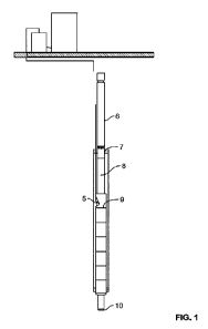
[0012] Figure 1 depicts a schematic of an exemplary embodiment of a disclosed
system.
[0013] Figure 2 depicts a schematic of an upper portion of an exemplary pump.
[0014] Figure 3 depicts a schematic of a middle portion of an exemplary pump.
[0015] Figure 4 depicts a schematic of a lower portion of an exemplary pump
and
upper portion of a gas separation module.
[0016] Figure 5 depicts a schematic of a lower portion of an exemplary pump
and
upper portion of an exemplary gas separation model.
[0017] Figure 6 depicts a schematic of an lower portion of an exemplary gas
separation module and upper portion of a seal section.
[0018] Figure 7 depicts a schematic of a portion of an exemplary seal section.
[0019] Figure 8 depicts a schematic of a portion of an exemplary thrust
chamber in
the lower portion of the seal section.
3
CA 03152155 2022-3-22
WO 2021/067101
PCT/US2020/052256
[0020] Figure 9 depicts a schematic of a portion of an exemplary thrust
chamber and
motor head module.
[0021] Figure 10A depicts an exemplary embodiment of a disclosed motor.
[0022] Figure 10B depicts a schematic of a portion of an exemplary motor head
module.
100231 Figure 11 depicts a schematic of a portion of an exemplary power
module.
[0024] Figure 12 depicts a schematic of portion of an exemplary base module.
[0025] Figure 13 depicts a schematic of a portion of an exemplary central heat
exchange module.
[0026] Figure 14 depicts a schematic of a portion of an exemplary lower heat
exchange module.
[0027] Figure 15 depicts a schematic of a portion of an exemplary base module
with
lubricant return.
[0028] Figure 16 A, B, and C, depict schematics of an exemplary central heat
exchange module.
[0029] Figure 17 A, B, and C depict schematics of an exemplary lower heat
exchange
module.
[0030] Figure 18 depicts an exemplary flangeless connection.
[0031] Figure 19A depicts an exemplary assembled sleeve assembly.
[0032] Figure 19 B and C depict components of an exemplary sleeve assembly.
[0033] Figure 20A and B depict embodiments of a bushing with a surface
feature.
[0034] Figure 21 shows Stator Lamination with Phase Alignment Mark.
[0035] Figure 22 shows Stack Lamination with Phase Alignment Mark.
[0036] Figure 23 shows Stator Alignment Mark when installed in motor Housing.
[0037] Figure 24 shows Stator Alignment Mark transferred to outside of Motor
4
CA 03152155 2022-3-22
WO 2021/067101
PCT/US2020/052256
Housing when assembled.
[0038] Figure 25 shows Phases aligned when motors coupled together.
[0039] Figure 26 shows Phases aligned.
[0040] Figure 27 shows Phase U, V, and W windings.
[0041] Figure 28 shows Rotor shown with Retention sleeve.
[0042] Figure 29 shows Rotor Shown without retention Sleeve with dividing
strip
between magnetic poles.
[0043] Figure 30 shows Pole division aligned with keyways and Pole Position
notch
on end of shaft.
[0044] Figure 31 shows Coupling alignment notch lined up with Pole Position
Notch
to align Rotors.
[0045] Figure 32 shows Rotors coupled together with poles aligned.
DETAILED DESCRIPTION OF THE INVENTION
[0046] In the following description, certain details are set forth such as
specific
quantities, sizes, arrangements, configurations, components, etc., so as to
provide a thorough
understanding of the present embodiments disclosed herein. However, it will be
evident to
those of ordinary skill in the art that the present disclosure may be
practiced without such
specific details. In many cases, details concerning such considerations and
the like have been
omitted inasmuch as such details are not necessary to obtain a complete
understanding of the
present disclosure and are within the skills of persons of ordinary skill in
the relevant art.
[0047] For the purposes of clarifying the various embodiments of the disclosed
inventions, the systems and assemblies described below are presented in the
context of an
exemplary electric submersible pump. It will be apparent to those of ordinary
skill that the
disclosed system may be utilized with other equipment, components, and
applications.
CA 03152155 2022-3-22
WO 2021/067101
PCT/US2020/052256
[0048] Exemplary Electric Submersible Pump Embodiments
[0049] In a non-limited exemplary embodiment, the disclosed inventions relate
to an
electric submersible pump (EPS) assembly. As shown in Figure 1, the exemplary
ESP
comprises at least one centrifugal pump module (6), a gas separator (7), a
seal section (8), an
electric motor (9) with an active cooling system, and a downhole sensor unit
(10). In
operation, a motor generates torque, which is communicated through a motor
shaft into a seal
section shaft. The seal section shaft transmits torque up to the gas separator
shaft, which
transmits torque to the pump module. The pump module utilizes the motor
generated torque
to lift wellbore fluid up a well bore.
[0050] As shown in Figure 2, a pump module (6) may have a discharge head (14).
The discharge head (14) may be integral to the pump module (6) or be attached
by any of a
variety of suitable techniques as known in the art. The discharge head (14)
may be connected
via a flange to the pump head (16) using a flange or flangeless connection. In
some
embodiments, the discharge head (14) will be connected to the pump head (16)
using
corrosion resistant fasteners (15) such as, for example, screws. A pump shaft
(18) may use a
split ring to lock into an axially adjustable assembly (19). The pump shall
(18) may include a
keyway including, for example, dual keyways, that attach the impellers (23)
and bearing
sleeves (24) to the shaft. In many embodiments, the impellers (23) and/or
bearing sleeves
(24) are rotationally fixed to the shaft (18). It will be understood that the
term impeller, as
used herein, may refer to any rotating component that is used to move a fluid.
[0051] A diffuser or, in some embodiments, a stack of diffusers (22) with
bearing
bushings, and impellers (23) may be placed inside the pump housing (17). A
compression
tube (21), a radial bearing support (20) and/or a pump head (16) may also be
secured at least
partially within the pump housing (17). In some embodiments, the pump head
(16) may
contain a high speed, self-aligning radial bearing system. In some
embodiments, a high
6
CA 03152155 2022-3-22
WO 2021/067101
PCT/US2020/052256
speed, self-aligning radial bearing system may be separate from the pump head
or integral to
the pump head.
[0052] As shown in Figure 3, a pump module (6) has at least one radial bearing
support (25). In preferred embodiments, radial bearing support (25) comprises
a radial
bearing system comprising a bushing housed in a bearing support and a sleeve
(25A)
mounted on a shaft. In preferred embodiments, the radial bearing system
comprises a high-
speed, self-aligning (HSSA) bearing.
[0053] As shown in Figure 4, a pump shaft (18) may have splines which connect
to a
coupling (28). In some embodiment, the splines described here, as well as
throughout the
application, may be involute splines, SAE6 splines, or other variations which
allow a shaft to
connect to a coupling. The coupling (28) may transmit torque from the shaft of
a gas
separator module (7) to the pump shaft. The bottom flange (27) of the pump
module (7) may
be secured to the top flange (30) of a gas separator module (7) using
fasteners (29) which
may include, for example, high strength corrosion resistant screws. In many
embodiments,
impellers (23) and bearing sleeves (24) form a rigid connection with the pump
shaft (18).
The bottom flange (27) may contain a radial bearing system, preferably
comprising a HSSA
bearing used to provide radial support to the pump shaft (18). It will be
appreciated that the
terms bottom flange and base may be used interchangeably throughout the
specification. It
will also be appreciated that the terms top flange and head may be used
interchangeably
throughout the specification.
100541 As shown in Figure 5, a gas separator module (7) may comprise a top
flange
(30) with a HSSA bearing (31) and phase crossover (32). Phase crossover (32)
directs the
gas phase of the production fluid to the wellbore annulus and the liquid phase
into the pump.
A spiral inducer (34) may be locked to the gas separator shaft (33) via a
keyway or dual
keyways. A gas separator housing (103) may be fitted with sleeves (35), to
protect the inner
7
CA 03152155 2022-3-22
WO 2021/067101
PCT/US2020/052256
surface of the gas separator housing from abrasive wear and corrosion. In some
embodiments, these sleeves (35) may comprise a metal ceramic such as, for
example,
tungsten carbide, silicon carbide, or zirconium carbide, and/or other
materials that provide
wear resistance, abrasion resistance, corrosion resistance, or other desirable
properties.
[0055] As shown in Figure 6, the bottom flange (38) of the gas separator
module (7)
may comprise a HSSA radial bearing and have at least one port for the inflow
of wellbore
fluid. Wellbore fluid may refer to single and/or multi-phase wellbore or
formation fluid. In
some embodiments, the bottom flange (38) of the gas separator module may be
fitted with a
screen (104) for removing debris from the wellbore fluid. Torque may be
transmitted to the
gas separator shaft (33) from the seal section (8) through a splined coupling
(105). The
bottom flange (38) of the gas separator (7) may be connected to a flange (41)
of the seal
section (8) via high strength corrosion resistant screws (39).
[0056] The seal section (8) may be a multi-chamber assembly which serves at
least
one of four main functions: (1) transmitting torque from the motor module to
the pump
module; (2) absorbing thrust from the pump module; (3) protecting an internal
chamber of the
motor module from wellbore fluid; and/or (4) reducing a pressure differential
between the
interior and exterior of the motor. It will be appreciated that the terms seal
section, equalizer,
and/or protector may be used synonymously within the industry to refer to a
seal section
[0057] In some exemplary embodiments, a seal section (8) may have a top flange
or
head (41) with a HSSA bearing, a dual key shaft and/or seal section shaft
(40), and a
mechanical seal (42). In some embodiments, the seal section shaft (40)
comprises splines on
both ends. In some embodiments, the mechanical seal (42) is a high-speed
mechanical seal
configured to protect the seal section (8) from wellbore fluid ingress around
the shaft (40). In
preferred embodiments, the seal section shaft (40) is fitted with a 1-1SSA
bearing sleeve (43),
which interact with a HSSA bearing bushing. Top flange (41) of the seal
section may have a
8
CA 03152155 2022-3-22
WO 2021/067101
PCT/US2020/052256
vent port (106) for removal of air or other gases when the internal chamber of
the electric
motor is filled with lubricant. In some embodiments, the lubricant serves as a
coolant and/or
is a dielectric or substantially dielectric fluid. Top flange (41) may also
have a tangential port
(107) for removal of sediment, particulate, or other solids, around the
mechanical seal (42).
The body of the top flange may have a port with a tube (109) inserted in it
which facilitates
the transmission of an external hydraulic pressure from the wellbore fluid to
the filling fluid
and/or lubricant of the seal section and/or electric motor. In some
embodiments, the tube
(109) follows a labyrinth scheme. In some embodiments, the labyrinth
transmission of
hydrostatic pressure between the external wellbore fluid and internal
lubricant may be carried
using tube (109) and tube (110). The seal section head (41) may be connected
to the upper
seal section housing (44).
100581 As shown in Figure 7, the bottom of the upper seal section housing (44)
may
be connected to the upper seal section body (46) where a second mechanical
seal (45) may be
installed. In such embodiments, the second mechanical seal (45) separates the
labyrinth
chamber from a bag chamber, additional labyrinth chambers, or combinations
thereof. The
seal section body may also contain a HSSA bearing, (111), a vent port (112)
and/or a
connecting channel (113) between an upper labyrinth chamber and a central
chamber of the
bag chamber section and/or additional labyrinth chambers. The specific
configuration of
labyrinth chamber and/or bag chamber may depend on the conditions of the well,
other
components of the ESP, and/or other factors.
100591 The upper seal section body (46) may be connected to the central seal
section
housing (114). The bottom portion of the upper seal section body (46) may be
fitted with a
tube (115) of the second labyrinth to transmit hydrodynamic and/or hydrostatic
pressure from
the top chamber to the central chamber. The central seal section housing (114)
may be fitted
with an upper bag support (47) and the bag may be secured with a clamp (116)
to the upper
9
CA 03152155 2022-3-22
WO 2021/067101
PCT/US2020/052256
bag support (47). In some embodiments, the upper bag support (47) may be
connected to a
lower bag support (118) via a support tube (117). Support tube (117)
facilitates a rigid
connection between the upper bag support (47) and lower bag support (118). In
some
embodiments a single bag may be used. In other embodiments a plurality of bags
may be
arranged in succession using a similar mounting technique.
[0060] As shown in Figure 8, a lower bag support (118) may be connected to a
lower
seal body (49) between the central seal section housing (114) and the thrust
chamber housing
(50). The lower seal section body (49) may be fitted with a HSSA bearing (119)
andlor a
vent port (120). The lower seal section body (49) may contain a high-speed
mechanical seal
and a HSSA bearing and may be threaded into the thrust chamber housing (50).
In some
embodiments, the thrust chamber housing (50) contains single, dual, or
multiple thrust
bearings (51) and (52).
[0061] In some embodiments, each of the thrust bearings (51 and 52) may be
fitted
with a spring damper (121 and 122). The spring dampers may facilitate a more
even or
substantially uniform distribution of the operational thrust load between the
thrust bearings
(51 and 52). In some embodiments, the spring dampers may comprise a Belleville
washer
stack. In some embodiments, the washer stack is run in a parallel
configuration to promote
even thrust load transfer across the two thrust bearings.
[0062] The top thrust runner (51A) may be dual-sided and engage against a
static face
(123) to absorb potential up-thrust. Up-thrust may be encountered during start-
up. A down-
thrust face on the top thrust runner (51A) may engage against the upper thrust
bearing
assembly (51) if down-thrust is encountered. In some embodiments, a single
sided runner
(52A) may engage against a lower thrust bearing assembly (52) in the event of
down thrust.
[0063] A thrust chamber heat exchanger may comprise an inner wall (124). In
some
embodiments, the exterior of this inner wall may be spiraled or otherwise
comprise a helical
CA 03152155 2022-3-22
WO 2021/067101
PCT/US2020/052256
or other tortuous pathway used to move motor oil or other lubricant from the
top of the thrust
chamber to the bottom of the thrust chamber in close proximity to the thrust
chamber housing
50. The lubricant pathway between the inner wall of the thrust chamber heat
exchanger and
the thrust chamber housing (50) may be helical or otherwise tortuous path in
order to increase
the residence time of the lubricant in the heat exchanger pathway, thereby
increasing the
amount of heat dissipated Through the thrust chamber housing (50) to the
wellbore fluid.
Once the circulated lubricant reaches the bottom of the thrust chamber it may
passes through
a filter (126) before being circulated through the thrust chamber again.
[0064] In some embodiments, the lubricant has a high dielectric strength
andior a
high viscosity. In some embodiments, the lubricant has a dielectric of greater
than 20 KV, or
greater than 25 KY, or greater than 30 KV, or greater than 35 KY. In some
embodiments, the
lubricant has a dielectric of at most 20 KY, or at most 25 KV, or at most 30
KY, or at most
35 KV.
[0065] In some embodiments, the lubricant has a viscosity at 40 C of at least
60
CST, or at least 70 CST, or at least 80 CST, or at least 100 CST, or at least
120 CST, or at
least 140 CST. In some embodiments, the lubricant has a viscosity at 40 C of
at most 70
CST, or at most 80 CST, or at most 100 CST, or at most 120 CST, or at most 140
CST, or at
most 160 CST
[0066] In some embodiments, the lubricant has a viscosity at 100 C of at
least 5
CST, or at least 7 CST, or at least 10 CST, or at least 12 CST, or at least 14
CST, or at least
16 CST. In some embodiments, the lubricant has a viscosity at 100 C of at
most 7 CST, or
at most 10 CST, or at most 12 CST, or at most 14 CST, or at most 16 CST, or at
most 18
CST.
[0067] As shown in Figure 9, the lower part of the thrust chamber housing (50)
may
be designed with a threaded connection. This threaded connection may be used
to connect
11
CA 03152155 2022-3-22
WO 2021/067101
PCT/US2020/052256
the thrust chamber housing (50) to the seal section base (56) which may be
fitted with a
HSSA bearing (127) and/or a relief valve (128) for factory filling of the seal
section with
coolant, lubricant, dielectric fluid, or a fluid with more than one of these
properties.
[0068] The seal section base (56) may be fitted with a screw (129) which
actuates the
valve (128) and allows for the flow of The lubricant fluid into the free
cavity between the
bottom flange of the seal section and the top flange of the motor module.
Bottom splines on
the seal section shaft (40) may be mated to a coupling (131), which may be
used to transmit
torque from the motor head module shaft (59) to the seal section shaft (40),
[0069] As shown in Figure 10A, in some exemplary embodiments, the motor module
(9) may be a permanent m,agnet synchronous motor of modular construction. The
combined
motor module (9) may comprise, a head module (310), Power modules (320), and
base
module (330).
[0070] As shown in Figure 10B, in some embodiments, the head module (310)
comprises a HSSA bearing as well as a head (57), a hollow head module shaft
(59) which
may have splines, a head module housing (134), a terminal block (60), and/or a
flangeless
connection (64) that may be used to mate the head module to the top of a power
module.
[0071] The terminal block (60) may hold three terminals that mate to the motor
lead
cable and seal the connection against the ingress of wellbore fluids. These
terminals may be
connected internally via lead wire (132) to the female terminals in the
insulation block (68).
The bottom part of the head (57) may be fitted with a protective insert (61)
which may be
used to protect the lead wire from the rotating head module shaft (59)
[0072] The head module (310) may also be also fitted with a filling valve
(133) which
may be used to fill the internal chamber of the electric motor and/or lower
chamber of the
seal section with lubricant when the unit is run in combination with a seal
section (9).
[0073] The head module housing (134) may be threaded on to the head (57)
and/or a
12
CA 03152155 2022-3-22
WO 2021/067101
PCT/US2020/052256
bearing support (71). In some embodiments, the bearing support is integral to
the head (57).
A HSSA Bearing (62) may be installed in the head module housing and held in
place by a
retaining nut. In certain embodiments, the bearings support, whether integral
to the head or a
separate component, may also comprise mounting holes for any female terminals
that connect
to the male terminals on a power module.
[0074] The lower part of the head module housing (134) may have a flangeless
connection (64). In an exemplary flangeless connection (64), the threads on
either end may
be in opposite directions from one another to enable a threaded connection to
a power module
(320) without an external upset along the exterior of the motor. For example,
the flangeless
connection (64) may make up to the head module housing (134) via right hand
threads, while
the opposite end may make up to the power module housing (136) which contains
left-hand
threads. It will be appreciated that right-hand threads turn in an opposing
direction as
compared to left-hand threads. This connection may then be secured by locking
a retaining
nut (65) against the housing of the power module. The connection may also be
secured using
a set screw or other similar retaining method. As the connection is made,
special alignment
tools may be used to ensure that the power terminals (63) and (68) and shaft
coupling are
mated properly. The lower splines of the head module shaft (59) may connect to
a coupling
(135) designed to transmit torque from the shaft of the rotor (66) in the
power module to the
head module shaft (59). A bearing support (136) may be located in the upper
end of a power
module (320) where an upper HSSA bearing bushing (137) may be located and/or
where a
power module rotor (66) may be positioned.
[0075] As shown in Figure 11, a wound stator core (72) may be positioned
within the
power module housing (67). The winding coils may be located inside the stator
core (72). A
lower bearing support (75) may be positioned inside the power module housing
(67) below
the winding end coils (73). The lower bearing support (75) may be fitted with
a HSSA
13
CA 03152155 2022-3-22
WO 2021/067101
PCT/US2020/052256
Bearing bushing (76) and a corresponding HSSA Bearing sleeve (74). HSSA
bearing sleeve
(74) may be connected to a rotor (66).
[0076] In some embodiments, both the upper and lower end of the rotor (66) are
associated with axial thrust pads (79) which allow the rotor (66) to self-
align within the
magnetic field of the wound stator core (72).
100771 A lower bearing support (75) may have mounting slots for the lower
terminals
(138) from the wound stator core (72) above. In some embodiments, a lower
portion of the
power module housing (67) may utilize a flangeless connection system similar
to or
substantially the same as the flangeless connection previously mentioned.
100781 As shown in Figure 12, a motor base module (330) may comprise a base
module housing (88), a hollow shaft (80) with a HSSA bearings sleeve, a
bearing support
(83) with a HSSA bearing bushing, an impeller (84) and/or an adjustable axial
thrust pad
(85). In some embodiments, the bearing support (83) of the base module (320)
may contain
mounting points for the male terminals (82) that connect to the female
terminals of a lower
power module. In some embodiments, terminals (82) may be connected with a
copper bus to
create a wye point that connects all three phases of the motor. A lower power
module
housing (86) may be mated to the base module housing (88) via a split ring
(87) or flangeless
connection system.
100791 In some embodiments, the lower end of the rotor shaft (66) may be mated
to a
base module shaft (80) via a splined coupling (90).
100801 In some embodiments, a centrifugal pump impeller (84) may be mounted on
the base module shaft (80). The impeller (84) may be fitted with an abrasive-
resistant runner
which may be configured to contact a thrust bearing (85). The thrust bearing
(85) may have
swiveling support (91) with a spring insert (92), which facilitates more
uniform contact of the
friction surfaces of an axial bearing (93). The body of the axial bearing (93)
may rest on a
14
CA 03152155 2022-3-22
WO 2021/067101
PCT/US2020/052256
connecting coupling (94) and be fitted with an adjusting support (95) which
may be used to
adjust the axial clearance of the rotors throughout the motor system.
[0081] In some embodiments, the elements of the base module (320) may have
holes
which form a channel for a sensor wire and/or a thermocouple to be passed
through. These
wires may go through the central channel of a heat-exchanger module to a
flange for a
downhole sensor (10).
[0082] Connecting coupling body (97) may include an upper and/or lower thread
which may be used to secure the base module housing (88) to a central heat
exchange module
(410) exterior housing (98). Connecting coupling (97) may have tangential
channels which
may be used to direct the flow of lubricant into a pathway between the
exterior housing (98)
and the interior housing (100) of the central heat exchange module (410). In
some
embodiments, the flow in this pathway is in a spiral or helical motion due to
the outer wall of
the interior housing (100) having a guide vane connected in a helical path to
direct the flow
of lubricant. This helical pathway may be used to increase the residency time
of the lubricant
and increase the amount of heat transferred from the lubricant to the wellbore
fluid. In some
embodiments, the internal chamber of the interior housing (100) may be
comprise
displacement rings (101) which reduces the volume of the filling lubricant in
the internal
chamber of the exchanger. In some embodiments, the displacement rings (101)
may
comprise a low coefficient of thermal expansion (CTE) material_
[0083] As shown in Figure 13, once the lubricant reaches the bottom of the
central
heat exchange module (410) it may enter a connecting coupling via a port (146)
and
crossover the connection through channels (147) which direct the flow into the
outer channel
of the lower heat exchange module (450) defined in part by lower heat exchange
module
exterior housing (148).
[0084] As shown in Figure 14, the lower portion of the exterior housing (148)
of the
CA 03152155 2022-3-22
WO 2021/067101
PCT/US2020/052256
lower heat exchange module (450) may have a threaded connection with a bottom
flange
(149). The bottom flange may be used to connect a downhole sensor and may be
fitted with a
filling valve (150) which may be used to fill the internal chamber of the heat
exchanger with
lubricant.
[0085] The lubricant may flow through the outer pathway (453) of the lower
heat
exchanger in order to dissipate heat from the lubricant to the exterior
housing and into the
well bore fluid. Then lubricant may flow from an outer pathway (453) of the
lower heat
exchange module (450) into the interior of the lower heat exchange module via
ports (151)
and may be passed by and/or through a magnet trap (152) to capture any
particulate, such as,
for example, ferrous wear debris. A lubricant return tube (153) may connect
the base and
head of the lower heat exchange module (450). In some embodiments, the
lubricant return
tube (153) may provide rigidity and/or a mounting frame for displacement rings
(154). The
lubricant return tube (153) may have several openings from the exterior to the
interior that
may be covered with a fine mesh filter to reduce the number of impurities
and/or non-ferrous
materials that are introduced into the motor. In some embodiments, this mesh
filter may be a
screen with substantially uniform pore size. In some embodiments, the pores
are at least
about 10 p.m, or at least about 20 gm, or at least about 25 pm, or at least
about 30 pm, or at
least about 40 pm wide. In some embodiments, the pores are at most about 10
pm, or at most
about 20 pm, or at most about 25 pm, or at most about 30 pm, or at most about
40 pm wide..
[0086] As shown in Figure 15, once the lubricant enters the return tube (153)
it may
travel up through the return tubes of one or a plurality of central heat
exchange modules (410)
through connecting tubes (155) and/or through a return path until it reaches
the motor base
module (330). The cooled and filtered lubricant may then be returned through
base module
shall (80) to the rotor (66) and then circulated up through the various motor
modules and/or
seal section before circulating back through the central (410) and lower (450)
heat exchange
16
CA 03152155 2022-3-22
WO 2021/067101
PCT/US2020/052256
modules.
[0087] It will be apparent to one of ordinary skill that elements of the
exemplary
embodiments described above may be utilized in alternate configurations, in
alternate
applications, with and/or without any of the other various elements described
herein and
otherwise known in The art. It will also be apparent that the various elements
associated with
any embodiment may be utilized with any other embodiment to achieve
substantially the
same or an analogous result.
[0088] High Speed Electric Submersible Pump
[0089] Some embodiments of the disclosed inventions belong to the category of
equipment related to wellbore fluid production via artificial lift with a
downhole submersible
pumping unit. Some embodiments include a permanent magnet motor, which may be
filled
with a coolant and/or lubricant In some embodiments, the disclosed pump may
operate at
greater than about 3,000 RPM, or greater than about 5,000 RPM, or greater than
about 6,000
RPM, or greater than about 7,000 RPM, or greater than about 9,000 RPM, or
greater than
about 10,000 RPM. In some embodiments, the disclosed pump may operate at less
than
about 3,000 RPM, or less than about 5,000 RPM, or less than about 6,000 RPM,
or less than
about 7,000 RPM, or less than about 9,000 RPM, or less than about 10,000 RPM.
[0090] Some embodiments of the disclosed inventions relate to an ESP assembly
which is shorter than a standard ESP for a given flow rate and/or head
pressure_ In some
embodiments, the length of a disclosed ESP is less than about 80 feet, or less
than about 60
feet, or less than about 50 feet, or less than about 45 feet, or less than
about 42 feet, or less
than about 35 feet, or less than about 30 feet, or less than about 25 feet, or
less than about 20
feet. In some embodiments, the length of a disclosed ESP is more than about 80
feet, or more
than about 60 feet, or more than about 50 feet, or more than about 45 feet, or
more than about
42 feet, or more than about 35 feet, or more than about 30 feet, or more than
about 25 feet, or
17
CA 03152155 2022-3-22
WO 2021/067101
PCT/US2020/052256
more than about 20 feet. In some embodiments, the length of a disclosed ESP is
greater than
about 80 feet, or greater than about 60 feet, or greater than about 50 feet,
or greater than
about 45 feet, or greater than about 42 feet.
[0091] Certain embodiments relate to an ESP assembly comprising a pump module,
wherein the pump module comprises a pump shaft and an impeller or impellers,
wherein the
pump shaft is operably connected to a motor shaft and wherein the impeller is
rotationally
fixed to the pump shaft by a keyway. In some embodiments, the ESP further
comprises a gas
separator module and/or an intake module wherein the gas separator comprises a
gas
separator shaft and an inducer, wherein the gas separator shaft is operably
connected to the
motor shaft and the inducer is rotationally fixed to the gas separator shaft
by a keyway. In
some embodiments, the inducer is a variable pitched inducer. In some
embodiments, the ESP
further comprises a seal section located between a motor module and the pump
module,
wherein the seal section is configured to transmit torque from the motor shaft
to the pump
shaft and absorb thrust from the pump module. In some embodiments, the ESP
further
comprises a motor module, wherein the motor module comprises an AC electric
permanent
magnet motor configured to operate at a desired rpm, the motor configured to
rotate a motor
shaft and/or a motor cooling system, wherein the motor cooling system
comprises a motor
cooling impeller, the motor cooling impeller configured to circulate lubricant
through a motor
module heat exchanger wherein the motor module heat exchanger comprises a
motor module
lubricant pathway, the motor module lubricant pathway configured to increase a
residence
time of the lubricant in the motor module heat exchanger.
[0092] In some embodiments, the ESP assembly can be installed in a well with a
casing having a drift ID of less than about 8 inches, less than about 7
inches, less than about 6
inches, less than about 5 inches, or less than about 4.6 inches, or less than
about 4.1 inches.
In some embodiments, the ESP assembly can be installed in a well with a casing
having a
18
CA 03152155 2022-3-22
WO 2021/067101
PCT/US2020/052256
drift ID of more than about 8 inches, more than about 7 inches, more than
about 6 inches,
more than about 5 inches, or more than about 4.6 inches, or more than about
4.1 inches. In
some embodiments, the ESP assembly can be installed in a well with a casing
haying a drift
ID of about 4.6 inches.
[0093] In some embodiments, the ESP assembly has a total dynamic head (TDH) in
feet to length in feet ratio of at least about 80, or at least about 100, or
at least 150, or at least
about 200, or at least about 220, or at least about 230. or at least about
250, or at least about
300. In some embodiments, the ESP assembly has a TDH to length ratio of at
most about 80,
or at most about 100, or at most 150, or at most about 200, or at most about
220, or at most
about 230, or at most about 250, or at most about 300.
[0094] In some embodiments, the ESP assembly has a break horse power (BHP) to
length in feet ratio of at least about 4, or at or at least about 5, or at
least about 7, or at least
about 9, or at least about 10, or at least about 10.5, or at least about 12.
In some
embodiments, the ESP assembly has a BHP to length ratio of at most about 4, or
at or at most
about 5, or at most about 7, or at most about 9, or at most about 10, or at
most about 10.5, or
at most about 12.
[0095] In some embodiments, the ESP produces at least about 400 barrels per
day
(bpd), or at least about 1,000 bpd, or at least about 2,000 bpd, or at least
about 2,500 bpd, or
at least about 3,000 bpd, or at least about 3,500 bpd, or at least about 4,000
bpd, or at least
about 5,000 bpd, or at least about 6,000 bpd, or at least about 7,000 bpd, or
at least about
7,500 bpd. In some embodiments, the ESP produces at most about 400 barrels per
day (bpd),
or at most about 1,000 bpd, or at most about 2,000 bpd, or at most about 2,500
bpd, or at
most about 3,000 bpd, or at most about 3,500 bpd, or at most about 4,000 bpd
or at most
about 5,000 bpd, or at most about 6,000 bpd, or at most about 7,000 bpd, or at
most about
7,500 bpd. Some embodiments are configured to produce between about 1,000 and
about
19
CA 03152155 2022-3-22
WO 2021/067101
PCT/US2020/052256
3,000 bpd without changing the downhole equipment. Preferred embodiments are
configured
to produce between about 400 and about 4,000 bpd without changing the downhole
equipment. As disclosed embodiments are configured to operate over a wide
range of
production volumes, the same ESP may be used as well production varies. Over
the life of an
oil and gas well, production may slow. Traditionally, this has required
removing one ESP,
configured to produce greater volumes of fluid and replacing it with a
different ESP
configured to produce lower volumes of fluid. This process may be repeated
multiple times
as the well produces smaller volumes. Each time an ESP or other down hole
component is
changed or replaced, the corresponding surface equipment may also need to be
replaced.
Each of these steps can lead to down time, lost or deferred production, and
increased
inventory requirements. Additionally, there is a risk of losing the well each
time it is sealed
so that equipment may be removed and/or reinstalled. These downsides can be
reduced
and/or avoided by utilizing disclosed embodiments which operate over a wide
range of
production volumes, thereby reducing or eliminating the need to change
downhole equipment
and/or corresponding surface equipment.
[0096] In certain preferred embodiments, the disclosed ESP can be installed in
wells
where the casing has a drift ID of about 4.6 inches, produces greater than
3,000 barrels per
day (bpd), has a TDH in feet to length in feet ratio of at least about 100 and
a BHP to length
in feet ratio of at least about 5.
[0097] In some embodiments of the disclosed ESP assembly, the seal section
comprises a port in fluid communication with the exterior environment
surrounding the seal
section and in fluid communication with an interior chamber or multiple
chambers, the
interior chamber configured to reduce a pressure differential between the
exterior of the
assembly to the interior of the assembly.
[0098] In some embodiments of the disclosed ESP assembly the seal section
CA 03152155 2022-3-22
WO 2021/067101
PCT/US2020/052256
comprises a seal section cooling system wherein the seal section cooling
system comprises a
seal section heat exchanger wherein the seal section heat exchanger comprises
a seal section
lubricant pathway, the seal section lubricant pathway configured to increase a
residence time
of the lubricant in the seal section heat exchanger. In such embodiments the
seal section may
further comprise a seal section lubricant return path.
100991 In some embodiments of the disclosed ESP assembly the seal section and
motor lubricant pathways are linked and a single heat exchanger system is
utilized to cool
both the seal section and the motor module. In such embodiments, the motor
lubricant return
path may also be linked to the seal section lubricant return path in order to
create a
continuous and/or linked heat exchange assembly for both the seal section and
motor module.
[00100] Some embodiments of the disclosed ESP assembly comprising at least
one or more than one high-speed self-aligning bearing.
[00101] In some embodiments of the disclosed ESP assembly, the motor
module heat exchanger comprises an upper heat exchange module and a lower heat
exchanger module, the lower heat exchange module comprising a screen
configured to trap
non-ferrous particles and a magnetic trap configured to trap ferrous
particles.
[00102] In some embodiments of the disclosed ESP assembly, the seal section
comprises a thrust chamber wherein the thrust chamber comprises at least two
thrust bearings
and wherein each thrust bearing is fitted with a spring damper designed to
distribute a thrust
load across two thrust bearings. In some embodiments, the spring damper may be
designed to
distribute the thrust load of the pump across two thrust bearings
substantially evenly.
[00103] In some embodiments of the disclosed ESP assembly, the motor
module comprises a head module, power module, and base module. In some
embodiments,
the motor module comprises more than one power module. The number of power
modules
may be adjusted depending on the power requirements of the ESP for a given
application.
21
CA 03152155 2022-3-22
WO 2021/067101
PCT/US2020/052256
[00104] In some embodiments of the disclosed ESP assembly, at least two
power modules are disposed between the head module and base module and a
flangeless
connection is used to connect the two power modules to each other. In some
embodiments, a
flangeless connection is used to connect the head module to a power module
and/or to
connect the base module to a power module.
[00105] In some embodiments of the disclosed ESP assembly, the motor
module further comprises a stator with a magnetic field wherein the motor
rotor is configured
to self-align within the magnetic field of the stator.
[00106] Some embodiments of the disclosed ESP further comprise an axial
seating system, configured to seat a motor rotor. In some embodiments, the
axial seating of
the rotor within the magnetic field of the stator may vary throughout the
operating range of
the system. The axial load faces may have slightly different microhardness in
order for
material to be removed from the lower microhardness face, if and as needed,
for the rotor to
seat at a given operating point. In axial thrust assemblies, the dynamic face
preferably has a
higher microhardness than the static face and the static face is preferably of
higher
compressive strength than that of the dynamic face. The methods and techniques
described
in ASTM C1424-15, Standard Test Method for Monotonic Compressive Strength of
Advanced Ceramics at Ambient Temperature, may be used to determine the
compressive
strength of a material_
[00107] In some embodiments, the dynamic face of an axial thrust assembly
comprises materials with a compressive strength of at least about 3,500 Mpa,
or at least about
3,700 Mpa, or at least about 4,000 Mpa, or at least about 4,200 Mpa, or at
least about 4,500
Mpa. In some embodiments, the dynamic face of an axial thrust assembly
comprises
materials with a compressive strength of at most about 3,500 Mpa, or at most
about 3,700
Mpa, or at most about 4,000 Mpa, or at most about 4,200 Mpa, or at most about
4,500 Mpa,
22
CA 03152155 2022-3-22
WO 2021/067101
PCT/US2020/052256
[00108] In some embodiments, the static face of an axial thrust assembly
comprises materials with a compressive strength of at least about 7,200 Mpa,
or at least about
7,500 Mpa, or at least about 7,800 Mpa, or at least about 8,000 Mpa, or at
least about 8,200
Mpa. In some embodiments, the static face of an axial thrust assembly
comprises materials
with a compressive strength of at most about 7,200 Mpa, or at most about 7,500
Mpa, or at
most about 7,800 Mpa, or at most about 8,000 Mpa, or at most about 8,200 Mpa.
[00109] In some embodiments, a rotor may be equipped with an axial load
face
on both the upper and lower ends of the rotor body. The corresponding stator
may be
equipped with a complementary upper and lower load face configured to absorb
and
distribute the load to the stator housing when interacting with the rotor
surfaces. This
arrangement allows the rotor to be preferentially aligned within the magnetic
field of the
stator throughout its operating range.
[00110] Active Cooling System
1001111 In some embodiments, an active cooling system is utilized to reduce
or
maintain the motor temperature and/or lubricant temperature. Disclosed active
cooling
systems may be utilized with a variety of motors, including, for example,
permanent magnet
motors and/or induction motors and/or may be utilized with a seal section or
other non-motor
machinery. It will be appreciated that features and elements of the disclosed
active cooling
system may be used with other disclosed embodiments as well as other equipment
and/or
machinery.
[00112] In some embodiments, a motor with the disclosed active cooling
system comprises an electric motor, an impeller, at least one central heat
exchanger module,
and a lower heat exchanger module. Each heat exchanger module typically
comprises a head
and a base. In disclosed embodiments, the impeller may be arranged to drive
lubricant into a
central heat exchanger. As shown in Figures 16 A-C, in some embodiments the
central heat
23
CA 03152155 2022-3-22
WO 2021/067101
PCT/US2020/052256
exchanger module (410) comprises an exterior housing (412), an interior
housing (415), and a
lubricant return tube (417) connected to the head and base of each central
heat exchanger
module. The interior housing (415) is positioned within the exterior housing
(412) and
arranged to create a central heat exchanger lubricant pathway (418) between
the interior and
exterior housing. The lubricant pathway (418) allows a thin layer of lubricant
to pass
between the interior and exterior housings. This creates a thermal pathway
allowing heat to
be transferred from the lubricant to the exterior housing and then to the
wellbore fluid. In
many embodiments, the lubricant pathway (418) is arranged in a helical
pattern, which causes
the lubricant to flow around the helical pathway, thereby increasing the
residence time that
the lubricant spends in the heat exchanger and allowing more heat to be
transferred from the
lubricant to the exterior housing and wellbore fluid. In some embodiments,
this helical
pathway is created using a wire or similar material wrapped around the
exterior of the interior
housing (415). Additionally or alternatively, a wire may be wrapped around the
interior of
the exterior housing, thereby creating a helical lubricant pathway between the
interior
housing and exterior housing. In preferred embodiments, the helical pathway is
created by
machining a pathway into the exterior of the interior housing (415).
[00113] In some embodiments, the lubricant pathway (418) defined by the
space between the interior and exterior housing is at least about 0.04 inches,
or at least about
0.06 inches wide, or at least about 0.065 inches wide, or at least about 0.07
inches wide, or at
least about 0.1 inches wide, or at least about 0.25 inches wide or at least
about 0.5 inches
wide. In some embodiments, the lubricant pathway (418) defined by the space
between the
interior and exterior housing is at most about 0.04 inches, or at most about
0.06 inches wide,
or at most about 0.065 inches wide, or at most about 0.07 inches wide, or at
most about 0.1
inches wide, or at most about 0.25 inches wide or at most about 0.5 inches
wide. In preferred
embodiments, lubricant pathway (418) is about 0.0675 inches wide.
24
CA 03152155 2022-3-22
WO 2021/067101
PCT/US2020/052256
[00114] As shown in Figures 17 A, B, and C, in some embodiments, a lower
heat exchanger (450) comprises a lower exterior housing (452), a lower
interior housing
(455), and a lower lubricant return tube (457). The lower interior housing
(455) may be
disposed within the lower exterior housing (452). This arrangement creates a
lower heat
exchanger lubricant pathway (458) between the interior and exterior housings.
The lower
lubricant return tube (457) may be disposed within the lower interior housing
(455) and be in
fluid communication with the lower heat exchanger lubricant pathway (458). As
cooling
lubricant circulates through the lower heat exchanger (450), it flows into the
lower lubricant
return tube (457), which may be fluidly connected to a central lubricant
return tube (417)
which circulates lubricant to the top of the central heat exchanger (410) and
back through the
motor. The central heat exchanger (410) may be connected to the lower heat
exchanger (450)
such that the central heat exchanger lubricant pathway (418) is fluidly
connected to the lower
heat exchanger lubricant pathway (458) and the central lubricant return tube
(417) is in fluid
communication with the lower lubricant return tube (457). This arrangement
allows lubricant
to be circulated through the motor and heat exchangers in order to cool the
motor and transfer
heat from the motor components to the wellbore fluid via the circulating
lubricant and heat
exchange modules.
[00115] In some embodiments, multiple central heat exchanger modules may
be arranged in a series. The central heat exchanger modules may be configured
such that the
lubricant return tube within the interior housing of each central heat
exchanger is connectable
to the lubricant return tube of a central heat exchanger module above and/or
below. The heat
exchanger lubricant pathways of each central heat exchanger module may also be
configured
such that it is connectable with the heat exchanger lubricant pathways of the
central heat
exchanger modules above and/or below as well. This modular arrangement allows
the
disclosed active cooling system to be customized based on the needs of a given
application.
CA 03152155 2022-3-22
WO 2021/067101
PCT/US2020/052256
When a greater degree of cooling is needed, additional central heat exchanger
modules may
be incorporated into the total motor system. This increases the length of the
combined
lubricant pathway, thereby increasing residence time and allowing a greater
amount of heat to
be transferred from the lubricant to the welt bore fluid. In applications
where total length is a
significant concern, a single lower heat exchanger module may be utilized
without any
central heat exchanger modules. In such embodiments, the lower heat exchanger
may be
connected to the motor base module. It will be appreciated that the lower heat
exchanger
module includes a lubricant pathway between the interior housing and exterior
housing which
dissipates heat from the lubricant to the well bore fluid and also serves to
direct lubricant
flowing through the lubricant pathway into the lubricant return tubes. This
allows lubricant
to be circulated throughout either one or a series of heat exchanger modules
before being
directed back through the motor and/or seal section. In particularly hot
wells, additional heat
exchanger modules may be added to maintain the motor temperature within a
desired range.
[00116] In an exemplary embodiment, the disclosed active cooling system may
be used in an ESP comprising a motor housing, a stator, and a rotor shaft. In
this exemplary
embodiment, the rotor shaft comprising an interior and an exterior and the
interior of the rotor
shaft is in fluid communication with the lubricant return tube of the lower
and/or central heat
exchange module. The rotor shaft may be arranged such that lubricant flows
from the
lubricant return tube through the interior of the rotor shaft into the
interior of the motor
housing between the motor housing and the stator. In some embodiments, the
stator may
comprise channels which are designed to accommodate the flow of lubricant
between the
stator and the motor housing.
[00117] Some embodiments of the disclosed active cooling system comprise a
filter and/or magnetic trap configured to remove particles from the
circulating lubricant In
some embodiments, the lower heat exchanger module comprises a screen designed
to remove
26
CA 03152155 2022-3-22
WO 2021/067101
PCT/US2020/052256
particles including non-ferrous wear products from the circulating lubricant.
In some
embodiments, the lower heat exchanger module comprises a magnetic trap
designed to
remove ferrous particles, including wear products from the circulating
lubricant By
removing particles, including ferrous and non-ferrous wear product from the
circulating
lubricant, the active cooling system helps to maintain the quality of the
circulating lubricant
This leads to a longer service life of the overall system incorporating the
active cooling
embodiments disclosed. ESPs which comprise the disclosed active cooling system
with
screen filter and magnet trap may have a longer service life than traditional
ESPs, resulting in
improved run life and service time.
[00118] In exemplary embodiments, the disclosed active cooling system is
used
in an ESP. In such embodiments, when the circulating lubricant reaches the top
of the upper
central heat exchanger module lubricant return tube, it then enters the
interior of a motor base
shaft and rotor shaft. In some embodiments, the motor base shaft and rotor
shaft as part of
the lubricant return pathway. The circulating lubricant flows up the rotor
shaft to the top of
the motor. In some embodiments, the rotor shaft includes holes from the
interior of the shaft
to the exterior where bushings or other components which may benefit from
cooling analor
lubrication are located. These holes allow circulating lubricant to contact
bushings, bearings,
or other components in order to cool and/or lubricate the components. The
lubricant then
continues to be circulated through the active cooling system.
[00119] In some embodiments, lubricant flows up the rotor shaft of the
motor
and into the shaft of the seal section. At that point, the lubricant may be
directed out of the
seal section shaft through holes leading from the interior of the shaft to the
exterior where
bushings or other components which may benefit from cooling and/or lubrication
may be
located. In some embodiments, lubricant may be directed out of the seal
section shaft by an
impeller located on or near the top of the lubricant flow path. The impeller
may drive the
27
CA 03152155 2022-3-22
WO 2021/067101
PCT/US2020/052256
circulating lubricant through holes leading from the interior of the shaft to
the exterior of the
shaft. In some embodiments, the lubricant may then flow through the motor
module and/or
enter the linked lubricant pathway between the interior and exterior housings
of the seal
section and motor module to dissipate heat before being recirculated through
the motor
module and seal section.
[00120]
In some embodiments, once circulating lubricant reaches the top of the
motor module, prior to reaching the seal section, the lubricant may be
directed out of the rotor
shaft by an impeller located on the top of the rotor. The impeller drives the
circulating
lubricant through exit holes leading from the interior of the rotor shaft to
the exterior of the
rotor shaft.
[00121]
In some embodiments, lubricant channels located between the stator
and the motor housing direct circulating lubricant between the stator and the
housing and
may, in some embodiments, direct lubricant through slots of the wound stator
core. This path
allows lubricant to pick up heat from the interior of the rotor shaft as well
as the stator and
motor housing. Once the lubricant has flown down the motor, between the stator
and
housing, the circulating lubricant enters the lubricant pathway of the upper
central heat
exchanger module where heat may be dissipated to the exterior housing of the
head
exchanger module and the wellbore fluid in contact with the outside of the
exterior housing.
[00122] Modular Motor System and Flangeless Connection
[00123]
As can be seen in Figure 10A, in some embodiments, the motor
system is built in modules that consist of a head module, a power module and a
base module.
In some embodiments, multiple power modules may be connected via a flangeless
connection
system in order to reach the desired application power requirements. It will
be appreciated
that the disclosed module systems and connections may be utilized with any
other disclosed
element or embodiment as well as with other equipment andlor machinery.
28
CA 03152155 2022-3-22
WO 2021/067101
PCT/US2020/052256
[00124] In some embodiments, two modules may be connected to each other
using a flangeless connection (510). As shown in Figure 18, in some
embodiments, the
flangeless connection (510) comprises a single piece housing coupling (512), a
lock nut
(515), and a spacer ring (518). In some embodiments using the flangeless
connection, the two
components or modules being joined will have opposite handed threads which
turn in
different directions. For example, if the lower end of a first power module is
to be joined to
the upper end of a second power module, the lower end of the first power
module may
comprise left-handed threads while upper end of the second power module may
comprise
right handed threads. In some embodiments, the single piece housing coupling
comprises
opposite handed threads on its upper and lower ends.
[00125] In some embodiments, the lock nut and spacer may be installed on
the
housing coupling. The upper and lower modules to be joined may be engaged with
the
threads on the single piece housing coupling and simultaneously madeup as the
single piece
housing coupling is rotated. Once completely inadeup the lock nut may be
tightened against
the spacer ring. Depending on the application, once the modules and/or
components are
threadedly- attached, the components may be secured by welding or another
method known to
prevent unthreading known in the art.
[00126] Some disclosed embodiments relate to a motor for an electric
submersible pump assembly, the motor comprising a head module; a base module;
and at
least two power modules disposed between the head module and base module. In
some
embodiments, each power module comprises a power module housing having an
upper and
lower portion; and at least two power modules are connected to each other
using a flangeless
connection, the flangeless connection comprising a housing coupling, a lock
nut, and a spacer
ring. In some embodiments, a power module may be connected to a base module
and/or a
head module using the disclosed flangeless connection regardless of the number
of power
29
CA 03152155 2022-3-22
WO 2021/067101
PCT/US2020/052256
modules in the ESP assembly.
[00127] In some embodiments, the upper portion of the power module housings
comprise threads rotating in a certain direction, for example, right handed
threads, and the
lower portion of the power module housings comprise threads rotating in the
opposite
direction, for example, left handed Threads. In some embodiments, the housing
coupling
comprises an upper portion and a lower portion, the upper portion of the
housing coupling
having right or left handed threads to connect to the lower portion of a power
module housing
and the lower portion of the housing coupling having opposite handed threads
to connect to
the upper portion of a power module housing.
[00128] Disclosed embodiments of the flangeless connection may help to
maximize the available motor diameter. The disclosed flangeless connection
also reduces
and/or eliminates choke points that may inhibit the flow of motor oil,
lubricant, and/or
dielectric fluid. Embodiments of the disclosed flangeless connection increase
the available
heat exchanger surface area, thereby allowing greater amounts of heat to be
transferred from
the motor or other components to the wellbore fluids. Disclosed embodiments
also allow the
various modules to be coupled in a manufacturing facility rather that at the
well site
environment This allows the operator to save time installing an ESP utilizing
the disclosed
features and leads to increased reliability of the assembled ESP and/or other
components.
[00129] HSSA Bearing Details
[00130] In some embodiments, the disclosed ESP components, as well as other
equipment, motors, and/or machinery may comprise high-speed self-aligning
(HSSA)
bearings. It will be appreciated that the disclosed bearing design may be
utilized with any of
the disclosed elements or embodiments as well as with other equipment or
machinery.
[00131] In some embodiments, a module may be equipped with a radial bearing
with the dynamic portion of the bearing (the bearing sleeve) being
rotationally fixed to a
CA 03152155 2022-3-22
WO 2021/067101
PCT/US2020/052256
rotating shaft. In such embodiments, the stator may be equipped with a
complementary static
portion (the bushing) which absorbs and distributes a radial load to the
stator housing. The
sleeve comprises material which may have a lower microhardness than the
bushing. This
arrangement allows for the sleeve (the dynamic face) to "wear-in" if necessary
in order to
reach an improved and/or optimum operating point. In some embodiments, the
sleeve will be
attached to a rotor which is contained in the magnetic field of the stator.
The disclosed
arrangement allows the rotor to reach an improved or optimum position within
the magnetic
field of the stator.
[00132] In some embodiments, the sleeve or a sleeve portion of a sleeve
assembly may comprise carbide. In certain embodiments, the sleeve comprises
tungsten
carbide with at least about 4% nickel, or at least about 5% nickel, or at
least about 6% nickel,
or at least about 7% nickel. In certain embodiments, the sleeve comprises
tungsten carbide
with at most about 4% nickel, or at most about 5% nickel, or at most about 6%
nickel, or at
most about 7% nickel.
[00133] In some embodiments, the bushing may be mounted on a fixed
support using one or multiple elastomeric bands. In some embodiments, the
elastomeric
bands comprise materials that, when in contact with a coolant, lubricant,
and/or dielectric
fluid, they will expand and lock the bushing to the support. In some
embodiments, the
elastomeric bands do not allow any axial or rotational movement of the
bushing. In some
embodiments, the anchoring strength on the bushing may be increased by adding
a groove or
helical groove on the outside of the bushing, thereby allowing the bands to
"grip" the
bushing. The elastomeric band may also help to center the bushing in the
bushing support
and/or provide a dampening effect in the event of any vibration.
[00134] In some embodiments, the bushing may have grooves which allow
lubricant to flow between the static and dynamic bearing faces. In radial
bearings, the static
31
CA 03152155 2022-3-22
WO 2021/067101
PCT/US2020/052256
face is the bushing and the dynamic face is the sleeve. These grooves allow
lubricant to flow
between the bushing and the sleeve and clear any particulate or debris, such
as, for example,
debris caused by wearing of the bearing faces. In some embodiments, the
lubricant cooling
and/or circulation system may comprise a screen and/or magnetic trap to remove
such debris
as the lubricant is circulated.
[00135] In some embodiments, the bushing may comprise an outer bushing
body and a bushing insert. The outer body may comprise a low Cm material. The
bushing
insert comprises a material of a higher microhardness than the associated
sleeve.
[00136] In some embodiments, a multi-piece bushing may allow for thinner
materials to be used. One advantage of thinner materials is that a higher
proportion of any
thermal growth will be in the axial plane rather than the radial plane. This
arrangement
allows tight tolerances to be maintained at high speeds and high temperatures.
[00137] As shown in Figure 19, in some embodiments, a sleeve assembly (530)
comprises a sleeve body (533) and at least two sleeves (535). In such
embodiments, the
sleeve body (533) and each sleeve (535) comprises a keyway. In some
embodiments, the two
sleeves (535) may be mounted onto the sleeve body (533) and the sleeve
assembly (530) may
be mounted onto a rotating shaft using the keyways and associated keys. In
some
embodiments, the sleeve assembly further comprises an inside limiting nut
which may be
threaded onto a rotating shaft and limit axial movement of the sleeve
assembly. In some
embodiments, the limiting nut may hold the keys, for example "L" keys, in the
keyway while
the sleeve assembly is mounted onto a shaft.
[00138] In some embodiments, a tapered centralizing ring may be mounted
with a set of keys to provide centralization of the sleeve assembly on the
shaft In some
embodiments, an outside limiting nut may be threaded into place but may be
stopped prior to
contacting the tapered centralizing ring. This arrangement allows for the
sleeve assembly to
32
CA 03152155 2022-3-22
WO 2021/067101
PCT/US2020/052256
have a small amount of axial movement between the inside and outside limiting
nuts in order
to assist in the bearing finding an improved or optimum operating point. Once
the outside
limiting nut is in place the edges of the tapered centralizing ring may be
peened into a
machined groove on the outside limiting nut.
100139]
In some embodiments, a rotor shaft may have elastomeric bands which
a sleeve assembly fits around. These elastomeric bands may help to direct
lubricant from the
interior of the shaft to the exterior of the sleeve body and onto the face of
the sleeves. This
arrangement allows lubricant circulating within the rotor shaft to lubricate
and cool the
bearing faces The elastomeric bands may also help to center the sleeve
assembly and
dampen any vibration.
100140]
In some embodiments, a pump and/or gas separator may comprise
HSSA bearings. An HSSA bearing for a pump may be comprise of a bushing and a
sleeve.
The bushing may be held onto a bushing support by an interference fit or any
other technique
known in the art. In some embodiments, elastomeric bands maybe used to prevent
rotation of
the bushing, the help center a shaft, and/or to dampen vibration.
11001411
In some embodiments a two-piece sleeve may be used. A two-piece
sleeve may comprise an outer sleeve and an inner sleeve. The outer sleeve may
be keyed to
the inner sleeve in order to rotationally fix the inner and outer sleeves of
the two-piece sleeve.
In some embodiments, the outer sleeve may be fluted and/or comprise a helical
groove on the
exterior to allow for the removal of particulate or other contaminants and/or
to promote the
flow of lubricant In some embodiments, the inner sleeve may be keyed to a
shaft via a dual
keyway. The inner sleeve may comprise low CTE materials designed to help
reduce thermal
growth in the radial direction. This arrangement may allow the outer sleeve to
be thinner
which further reduces radial thermal growth.
1001421
In some embodiments, the design of the high-speed self-aligning
33
CA 03152155 2022-3-22
WO 2021/067101
PCT/US2020/052256
(HSSA) radial bearings may be based on the concept that at high rotational
speed the
dynamic face (the rotating sleeve) performs better after finding its optimal
or improved
running position within the static face (the non-rotating bushing).
[00143] To facilitate this process, the materials of the sleeve and bushing
should have slightly different microhardness in order for material to be
removed from the
lower microhardness face, if or as needed, for the bearing to self-align. The
sleeve material
may additionally be of a higher flexural strength than the bushing material in
order to allow it
to overcome any bending stresses encountered during the process of self-
alignment. To
further facilitate the process of self-alignment, in some embodiments, the
sleeve assembly
may be allowed to move, at least to a degree, in the axial direction. In some
embodiments,
the sleeve assembly may be allowed to move at least about 20 mils, or at least
about 25 mils,
or at least about 30 mils, or at least about 40 mils. or at least about 50
mils, or at least about
60 mils, or at least about 70 mils, or at least about 75 mils. In some
embodiments, the sleeve
assembly may be allowed to move at most about 20 mils, or at most about 25
mils, or at le
most ast about 30 mils, or at most about 40 mils, or at most about 50 mils, or
at most about 60
mils, or at most about 70 mils, or at most about 75 mils.
[00144] Some embodiments of the disclosed inventions relate to a radial
bearing assembly suitable for mounting on a rotatable shaft, the radial
bearing assembly
comprising one or more radial bearings, each bearing comprising a bushing and
a sleeve, the
bushing and sleeve each comprising an interior and an exterior The interior of
the bushing
being in lubricated, engagement with the exterior of the sleeve, wherein the
bushing is
affixable to a non-rotatable bushing support and comprises a material having a
higher
microhardness than the sleeve and wherein the sleeve is configured to mount to
a rotating
shall and comprises a material having a higher flexural strength than the
bushing. In some
embodiments, the bushing comprises a material having a microhardness of at
least about
34
CA 03152155 2022-3-22
WO 2021/067101
PCT/US2020/052256
2,000 MPa, or at least about 2,500 MPa, or at least about 2,800 MPa, or at
least about 3,000
MPa, or at least about 3,200 MPa on the Knoop microhardness scale. In some
embodiments,
the bushing comprises a material having a microhardness of at most about 2,000
MPa, or at
most about 2,500 MPa, or at most about 2,800 MPa, or at most about 3,000 MPa,
or at most
about 3,200 MPa on the Knoop microhardness scale. In some embodiments, the
sleeve
comprises a material having a microhardness of at least about 1,000 MPa, or at
least about
1,500 MPa, or at least about 1,800 MPa, or at least about 2,000 MPa, or at
least about 2,200
MPa on the Knoop microhardness scale. In some embodiments, the sleeve
comprises a
material having a microhardness of at most about 1,000 MPa, or at most about
1,500 MPa, or
at most about 1,800 MPa, or at most about 2,000 MPa, or at most about 2,200
MPa on the
Knoop microhardness scale.
1001451 The methods and techniques described in ASTM C1326-13, Standard
Test Method for Knoop Indentation Hardness of Advanced Ceramics, may be used
to
determine the microhardness of a material.
[00146] In some embodiments, the sleeve comprises a material having a
flexural strength of at least about 1,000 Mpa, or at least about 1,300 Mpa, or
at least about
1,500 Mpa, or at least about 1,800 Mpa, or at least about 2,000 Mpa. In some
embodiments,
the sleeve comprises a material having a flexural strength of at most about
1,000 Mpa, or at
most about 1,300 Mpa, or at most about 1,500 Mpa, or at most about 1,800 Mpa,
or at most
about 2,000 Mpa. In some embodiments, the bushing comprises a material having
a flexural
strength of at least about 300 Mpa, or at least about 300 Mpa, or at least
about 400 Mpa, or at
least about 450 Mpa, or at least about 500 Mpa. In some embodiments, the
bushing
comprises a material having a flexural strength of at most about 300 Mpa, or
at most about
300 Mpa, or at most about 400 Mpa, or at most about 450 Mpa, or at most about
500 Mpa.
1001471 The methods and techniques described in ASTM C1161-02c(2008)el,
CA 03152155 2022-3-22
WO 2021/067101
PCT/US2020/052256
Standard Test Method for Flexural Strength of Advanced Ceramics at Ambient
Temperature,
may be used to determine the flexural strength of a material.
[00148] In some embodiments, the bushing interior comprises a plurality of
grooves configured to allow lubricant to flow between the bushing and the
sleeve and
wherein the grooves are configured to discharge debris. In some embodiments,
the grooves
are at least about 3.0 mm wide, or at least about 4.0 ram wide, or at least
about 4.5 mm wide,
or at least about 5.0 mm wide. In some embodiments, the grooves are at most
about 3.0 min
wide, or at most about 4.0 mm wide, or at most about 4.5 mm wide, or at most
about 5.0 mm
wide. In certain embodiments, the grooves are about 4.73 mm wide.
[00149] In some embodiments, as shown in Figures 20A and 20B, the bushing
(550) has a surface feature (553) configured to distribute lubricant as the
sleeve rotates. The
bushing (550) may have an groove, configured to facilitate and/or maintain the
build-up of
lubricant to be distributed onto the interface of the bushing (550) and
sleeve. This surface
feature (553) may facilitate removal of particulate. In some embodiments, this
surface
feature (553) has a larger radius on the leading edge than the trailing edge.
[00150] In some embodiments, the radial bearing assembly further comprises
an elastomeric band disposed between the bushing exterior and bushing support,
the
elastomeric band configured to expand when in contact with a lubricant and
prevent
substantial deleterious movement of the bushing relative to the bushing
support. In some
embodiments, deleterious movement comprises radial and axial movement. In some
embodiments, as shown in Figure 20A, the radial bearing assembly may further
comprise a
groove (555) in the bushing exterior wherein the groove is configured to
increase binding
between the bushing and the elastomeric band. In some embodiments, the groove
is helical
and the elastomeric band is configured to dampen vibration.
[00151] In some embodiments of the radial bearing assembly, the sleeve is
36
CA 03152155 2022-3-22
WO 2021/067101
PCT/US2020/052256
axially movable between about 1.5 mm and about 3.0 mm relative to the rotating
shaft. In
some embodiments, the sleeve may be axially movable relative to the rotating
shaft by at
least about 0.5 mm, or at least about 0.8 mm, or at least about 1.0 min, or at
least about 1.5
mm, or at least about 2.0 mm, or at least about 2.5 mm, or at least about 3.0
mm, or at least
about 3.5 mm, or at least about 4.0 mm. In some embodiments, the sleeve may be
axially
movable relative to the rotating shaft by at most about 0.5 mm, or at most
about 0.8 mm, or at
most about 1.0mm, or at most about 1.5 mm, or at most about 2.0 mm, or at most
about 2.5
mm, or at most about 3.0mm, or at most about 3.5 mm, or at most about 4.0 mm,
The
allowed axial movement of the sleeve relative to the shaft may allow a rotor
shaft to find an
improved or optimum position within the magnetic field of a stator.
1001521 In some embodiments of the radial bearing assembly, the sleeve
comprises two outer sleeves and an inner sleeve body, wherein the two outer
sleeves and
inner sleeve body each comprise a keyway. In some embodiments, the sleeve body
and the
rotating shaft each comprise an interior and an exterior. The sleeve body may
comprise an
opening allowing lubricant to pass from the interior of the sleeve body to the
exterior of the
sleeve body and the shaft may comprise an opening allowing lubricant to pass
from the
interior of the shaft to the exterior of the shaft. One or more elastomeric
bands may be
disposed between the exterior of the shaft and the interior of the sleeve body
creating a gap
for the flow of lubricant from the interior of the shaft to the exterior of
the sleeve body. In
some embodiments, the assembly further comprises a screen configured to be in
fluid
communication with a lubricant, the screen designed to remove wear products
from the
lubricant. In some embodiments, the assembly further comprises a magnetic trap
configured
to be in fluid communication with a lubricant, the magnetic trap designed to
remove ferrous
wear products from the lubricant
1001531 In some embodiments of the radial bearing assembly the bushing
37
CA 03152155 2022-3-22
WO 2021/067101
PCT/US2020/052256
comprises a bushing body and a bushing insert, wherein the bushing insert
comprises a
material having a higher tnicrohardness than the sleeve and wherein the
bushing body
comprises a low CTE material. In some embodiments of the radial bearing
assembly the
sleeve comprises an outer sleeve and an inner sleeve, wherein the inner sleeve
comprises a
low CTE material. In some embodiments, the low CM material has a CTE of at
least about
3.5, or at least about 4.0, or at least about 4.5, or at least about 5.0, or
at least about 5.5
gin/m- C. In some embodiments, the low CTE material has a CTE of at most about
3.5, or at
most about 4.0, or at most about 4.5, or at most about 5.0, or at most about
5.5 pm/m- C.. In
certain embodiments, the low CTE material has a CTE of about 4.9. Low cte
materials may
include, but are not limited to, for example, InvarTM, InovcoTm, KovarTM,
RodanTM,
TelcosealTm, SealvarTm, SelvarTm, Alloy 29-17Tm, Nib o KTm, DilverTm, Pernifer
29-18Tm,
Alloy 29-18Th% NicoselTm, NicosealTm, and/or TherloTm.
[00154] It will be appreciated that the disclosed bearings may be
incorporated
into any of the components and/or modules described herein including, but not
limited to the
pump modules, motor modules, gas separator, and/or seal section.
[00155] Symmetrical Rotor
[00156] Disclosed embodiments relate to or comprise a rotating rotor. In
some
embodiments, a symmetrical rotor may allow for a higher grade of balancing to
reduce and/or
minimize any mechanical vibration when the rotor rotates at operating speeds.
It will be
appreciated that the disclosed ESP embodiments may comprise a symmetrical
rotor and that
the features and elements disclosed herein may be used with any other
equipment or
machinery which utilizes rotating parts, pumps, motors, rotors, and/or
stators. The alignment
of various components, including for example, shaft splines, keyways,
impellers, lubricant
holes and/or bearing seats may all impact operation, particularly high-speed
operation. A
symmetrical rotor may have designated bronze end rings for removal of material
to achieve a
38
CA 03152155 2022-3-22
WO 2021/067101
PCT/US2020/052256
balance grade of G1 per ISO specification 21940-11:2016. These end rings may
be covered
with sleeves made of titanium or other materials and sealed with an anaerobic
gasket in order
to ensure that no material fills the area where material was removed which
could lead to
future imbalances. It will be appreciated that in some embodiments, the
symmetrical rotor is
vertically symmetrical in addition to axially and/or radially symmetrical. In
some
embodiments, a vertically symmetrical rotor does not include an impeller at
either end in
order to ensure vertical symmetry. In such embodiments, any necessary
impellers may be
relocated to other areas of the disclosed ESP assembly including, for example,
the seal
section and/or the top of the lubricant flow path.
[00157] Motor Base Thrust Module
[00158] Some disclosed embodiments comprise a motor base thrust module. It
will be appreciated that elements and feature of the disclosed thrust module
may be applied to
other embodiments as well as other equipment and/or machinery. A thrust runner
may be
connected to an impeller in the motor base. In some embodiments, a thrust
runner is
connected to the bottom of an impeller that drives the motor active cooling
system. In such
embodiments, the static face may be built into a body and/or assembly that may
be axially
adjusted to compensate for any variation it the position of the shafts of the
power modules.
[00159] The static face of the motor base thrust module may be centrally
mounted on a pivot head. In some embodiments, the static face may be tensioned
using
springs that facilitate evenly spreading the load across the bearing. In some
embodiments,
between 2 and 8 springs may be used. In preferred embodiments, six springs may
be used.
[00160] In some embodiments of the motor module base thrust module, the
dynamic face of the thrust runner may comprise a material with a higher
microhardness than
the material of the static face. In such embodiments of the thrust module, the
static face may
comprise a material with a lower microhardness than the dynamic face. The
static face may
39
CA 03152155 2022-3-22
WO 2021/067101
PCT/US2020/052256
also comprise a material compression of a higher compression strength than the
material of
the dynamic face.
[00161] One of many potential materials known to have a high compression
strength is carbon graphite. Carbon graphite is beneficially known to have
high compression
strength, low coefficient of friction and self-lubricating properties_ Carbon
graphite materials
are known to have a high operational temperature limit which may be beneficial
in some
embodiments due to the increased friction heat generated by some embodiments
of the
disclosed pump assembly at higher speeds. Thrust washers may additionally or
alternatively
comprise, for example, polymeric materials or other materials depending on the
application
conditions.
[00162] In some embodiments, the static and/or dynamic face of the motor
base
thrust module may comprise grooves. The grooves may be configured to
facilitate
maintaining a lubricant film or layer between the static and dynamic faces of
the motor base
thrust module,
[00163] Motor Filter and Magnet Trap
[00164] Some disclosed embodiments comprise a filter and/or magnet trap for
removing non-ferrous and/or ferrous particulate. It will be appreciated that
elements and
feature of the disclosed filter and magnetic trap may be applied to other
embodiments as well
as other equipment and/or machinery.
[00165] Some embodiments of the disclosed motor system comprise a lower
heat exchange module. The lower heat exchange module may comprise a shaft with
holes
from the outer diameter to the inner diameter. The lower heat exchange module
may
comprise a filter medium to filter lubricant which passes through the holes.
The filter
medium may include, but is not limited to screen mesh, fibrous mesh, or any
other material
capable of filtering non-ferrous contaminants from the circulating lubricant.
Some
CA 03152155 2022-3-22
WO 2021/067101
PCT/US2020/052256
embodiments may comprise a magnet trap configured to catch ferrous debris or
other
particles that may be produced during the operation of the motor. In some
embodiments, the
magnet trap may be positioned near the bottom of the lubricant return tube in
order to capture
any ferrous particles which may settle during circulation.
[00166] Dual Bearing Thrust Chamber and Integrated Heat Exchanger
1001671 Some disclosed embodiments comprise a dual bearing thrust chamber
and/or an integrated heat exchanger. It will be appreciated that elements and
feature of the
disclosed thrust chamber and heat exchanger may be applied to other
embodiments as well as
other equipment and/or machinery.
[00168] In some embodiments of the disclosed pump assembly, the seal
section
comprises a dual bearing thrust chamber configured to absorb thrust from the
pumps and
transmit rotation from the motor to the pumps. In some embodiments, the dual
bearing thrust
chamber allows axial load to be evenly distributed across two thrust bearings,
thereby
substantially doubling the amount of thrust the seal chamber can absorb. In
some
embodiments of the disclosed pump assembly, the axial thrust generated by the
pumps is
transferred entirely to the thrust bearings in the seal section thrust
chamber. In some
embodiments, no axial thrust is transferred to any bearing which provides
radial support.
[00169] In some embodiments, a thrust chamber arranged to transfer thrust
from a shaft to a thrust bearing comprises a shaft that is operably connected
to at least one
impeller. The impeller may be configured to generate downward thrust when it
is in
operation. The thrust chamber also comprises a thrust chamber outer housing, a
first thrust
runner, that is coupled to the shaft and comprises an upward facing thrust
transferring surface
and a downward facing thrust transfer surface. The thrust chamber may also
comprise a first
thrust bearing assembly coupled to the outer housing; wherein the first thrust
bearing
assembly comprises an upward facing thrust receiving surface and wherein the
first thrust
41
CA 03152155 2022-3-22
WO 2021/067101
PCT/US2020/052256
runner is configured to transfer downward thrust from the shaft to the first
thrust bearing
assembly. In some embodiments, an up-thrust bearing assembly may be coupled to
the outer
housing, wherein the up-thrust bearing assembly comprises a downward facing
thrust
receiving surface and wherein the first runner is configured to transfer
upward thrust from the
shaft to the up-thrust bearing assembly. In some embodiments, a second thrust
runner may
be coupled to the shaft and comprise a downward facing thrust transfer surface
and a second
thrust bearing assembly may be coupled to the outer housing, wherein the
second thrust
bearing assembly comprises an upward facing thrust receiving surface and
wherein the
second thrust runner is configured to transfer downward thrust from the shaft
to the second
thrust bearing assembly. Some embodiments may also comprise a first and a
second damper,
wherein the first damper is configured to absorb downward thrust from the
first thrust runner
and transfer the downward thrust to the first thrust bearing assembly and the
second damper
is configured to absorb downward thrust from the second thrust runner and
transfer the
downward thrust to the second thrust bearing assembly. In such embodiments,
the dampers
may be configured to spread axial load substantially evenly across at least
two thrust
bearings.
[00170] Preferred embodiments of the disclosed thrust chamber may comprise
a thrust chamber heat exchanger, wherein the thrust chamber heat exchanger
comprises a
thrust chamber interior housing and thrust chamber lubricant return path,
wherein the thrust
chamber interior housing is disposed within the thrust chamber outer housing
and defines a
thrust chamber heat exchanger lubricant pathway therebetween. In such
embodiments the
thrust chamber lubricant return path may be in fluid communication with the
thrust chamber
lubricant pathway and may be disposed within the interior housing.
[00171] In some embodiments, the shaft comprises an interior and an
exterior,
and the interior of the shaft may be in fluid communication with the lubricant
return path. In
42
CA 03152155 2022-3-22
WO 2021/067101
PCT/US2020/052256
some embodiments, the up-thrust bearing assembly comprises a static downward
facing
thrust receiving surface. In some embodiments, the upward facing thrust
receiving surfaces
of the first and second thrust bearing assemblies have a higher microhardness
than the
downward facing thrust transfer surfaces of the first and second thrust
runners.
[00172] In some embodiments, the dampers are configured to distribute
substantially even thrust load across the first and second thrust bearing
assemblies. In some
embodiments, the dampers may comprise Belleville washers and/or stacks of
Belleville
washers configured in parallel.
[00173] In some embodiments, the thrust chamber lubricant pathway is
substantially helical.
[00174] In some embodiments, the thrust chamber heat exchanger further
comprises a filter screen and/or a magnetic trap in fluid communication with
the thrust
chamber lubricant pathway
[00175] In some embodiments, the outer thrust housing is threadedly
connected
to a seal section, and the seal section is disposed between a motor module and
a pump
module. In some embodiments, the pump module comprises an impeller that
generates
downward thrust when in operation, and the downward thrust generated by the
impeller is
communicated to the thrust chamber shaft and transferred by the first and
second thrust
runners to the first and second thrust bearing assemblies which are axially
fixed to the thrust
chamber outer housing.
[00176] In certain embodiments, the lubricant pathway of the seal section
thrust
chamber may be in fluid communication with the lubricant pathway of the motor
module heat
exchangers, thereby creating a unified active cooling system for the motor
assembly and seal
section. In embodiments which utilize at least one active cooling system, the
cooler lubricant
may allow for a more viscous lubricant film to be maintained between an axial
thrust
43
CA 03152155 2022-3-22
WO 2021/067101
PCT/US2020/052256
transferring and thrust receiving surface. This viscous lubricant layer may
help extend the
life of the seal section thrust chamber as well as the other thrust
transferring and/or lubricated
components.
1001771
In addition to being utilized to cool motors, the disclosed active
cooling system may be utilized with a seal section. The disclosed seal section
may comprise
an impeller, interior housing, exterior housing, and lubricant return path.
The housings may
be arranged to create a seal section lubricant pathway between the interior
and exterior seal
housings, Lubricant may be driven by the impeller to flow through the
lubricant pathway,
thereby dissipating heat from the lubricant to the exterior seal housing and
wellbore fluid.
The lubricant may then be circulated through the lubricant return path to the
interior of the
seal section before circulating back through the lubricant pathway.
hi preferred
embodiments, the disclosed seal section cooling systems comprise a screen and
magnetic trap
to remove ferrous and non-ferrous particles from the circulating lubricant.
1001781
In some embodiments, the disclosed active cooling system may be
utilized with both a motor and seal section. In such embodiments, the seal
section lubricant
pathway may be fluidly connected to the central heat exchangers of the motor
section. The
lubricant return tube of the lower heat exchanger module may be fluidly
connected to the
lubricant return tubes of the central heat exchanger modules and also to the
lubricant return
path of the seal section heat exchanger modules. This arrangement allows
circulating
lubricant to cool and lubricate the components of the associated motor and
seal section. This
arrangement further allows lubricant in the seal section to be cooled by as
many heat
exchange modules as are required to maintain the desired operating temperature
relative to
the wellbore fluid. In some embodiments, the heat exchanger modules may be
configured to
maintain the temperature of the circulating lubricant to less than about 15 C
above the
temperature of the wellbore fluid, or less than about 10 C above the
temperature of the
44
CA 03152155 2022-3-22
WO 2021/067101
PCT/US2020/052256
wellbore fluid, or less than about 7 C above the temperature of the wellbore
fluid, or less
than about 5 C above the temperature or the wellbore fluid. In some
embodiments, the heat
exchanger modules may be configured to maintain the temperature of the
circulating
lubricant to more than about 15 C above the temperature of the wellbore
fluid, or more than
about 10 C above the temperature of the wellbore fluid, or more than about 7
C above the
temperature of the wellbore fluid, or more than about 5 C above the
temperature of the
wellbore fluid.
[00179] In some alternative embodiments of the disclosed pump assembly may
be arranged to pump more wellbore fluid, and thereby generate more downward
thrust than
some embodiments of the seal section thrust chamber is designed to absorb. In
such
embodiments, pump modules may be configured to comprise a thrust runner and
thrust
absorbing assembly. In some embodiments, the pump module thrust absorbing
assembly
may be self-leveling. The pump module thrust absorbing assembly may comprise
bushings
and sleeves for radial support in addition to thrust runners and thrust
absorbing surfaces for
absorbing axial support.
[00180] Gas Separator Inducer and Carbide Lined Separation Chamber
[00181] Some disclosed embodiments comprise a gas separator inducer and/or
a carbide lined separation chamber. It will be appreciated that elements and
feature of the
disclosed gas separator and separation chamber may be applied to other
embodiments as well
as other equipment andior machinery.
[00182] In some embodiments, the disclosed ESP assembly comprises a gas
separator configured to separate gas phase and liquid phase. In some
embodiments, the gas
separator comprises an inducer, for example a variable pitch and/or helical
inducer. In some
embodiments, the inducer may comprise vanes inclined towards the liquid flow
path. In some
embodiments, a separation chamber may be lined with carbide inserts and/or
comprise
CA 03152155 2022-3-22
WO 2021/067101
PCT/US2020/052256
abrasion resistant materials configured to prevent erosional wear from
abrasive solids. Some
embodiments of the disclosed gas separator may further comprise elastomeric
bands
connected to the carbide inserts, the elastomeric bands configured to dampen
and/or mitigate
vibration.
Aligned Permanent Magnet Motors Embodiments
[00183] Two, three, four or more permanent magnet synchronous motors may
be employed in series with any of the embodiments described above. It is
generally desirable
to properly align motors when employing two or more motors.
[00184] In one embodiment the present application pertains to a process for
aligning two or more permanent magnet motors each having a rotor and a stator.
Advantageously, the process can be used in conjunction with the various
embodiments of an
electrical submersible pump described above. Generally, the process involves
making a
phase identifying mark on each stator of the two motors to be connected. The
phase
identifying mark may be employed to start a winding on each stator at the
phase identifying
mark. The type of mark is not particularly critical and may vary depending
upon the type of
stator, other components, and the like. For example, the phase identifying
mark may
comprise a mark machined onto the stator, a painted mark, or an adhered mark.
[00185] The process generally comprises making a pole identifying mark on
each rotor of the two motors to be connected. As with the phase identifying
mark the type or
manner of making the pole identifying mark is not particularly critical and
may vary. For
example, the pole identifying mark may comprise a mark machined onto the
rotor, a painted
mark, or an adhered mark. In one embodiment, the pole identifying mark
comprises a notch
on an end of the rotor shaft wherein the notch is configured to mate with a
coupling
alignment notch as shown in for example, Figure 30-31.
[00186] Advantageously, the phase identifying marks may be used to align
the
46
CA 03152155 2022-3-22
WO 2021/067101
PCT/US2020/052256
phases of the stators while the pole identifying marks to align the poles of
the rotors. In some
embodiments it may be desirable to install each stator in one or more motor
housings. If so,
then it may be desirable to somehow indicate the location of the phase
identifying mark on
the exterior of the motor housing. That is, a symbol, machining, label, or
other indication is
made on the exterior of the motor housing to indicate that the phase
identifying mark lies
immediately below said symbol, machining, label, or other indication.
[00187] In another embodiment the present application relates to an
electric
motor (sometimes referred to as a motor module or power module above) for an
electric
submersible pump. The electric motor typically includes a first and a second
permanent
magnet motor. The first permanent magnet electric motor comprises a first
rotor with a first
pole identifying mark and a first stator with a first phase identifying mark.
The second
permanent magnet electric motor comprises a second rotor with a second pole
identifying
mark and a second stator with a second phase identifying mark. The type of
phase
identifying and pole identifying mark is not particularly critical so long as
the marks may be
employed to substantially align the phases of the first and second stators and
to substantially
align the poles of the first and second rotor.
[00188] The first and second permanent magnet motors may be coupled in any
convenient manner. In one embodiment the first permanent magnet motor
comprises threads
on an inner diameter which turn in a first direction and wherein the second
permanent magnet
motor comprises threads on an inner diameter which turn in a second direction.
A single-
piece housing such that described above, e.g., flangeless connection, may be
employed to
connect the two motors. Such a
single-piece housing coupling may comprises a first end and a second end. The
first end of
the single-piece housing coupling comprises threads on an outer diameter which
turn in a first
direction while the second end of the single-piece housing coupling comprises
threads on an
47
CA 03152155 2022-3-22
WO 2021/067101
PCT/US2020/052256
outer diameter which turn in a second direction. In this manner the first
permanent magnet
motor may be joined to the second permanent magnet electric motor using the
threads on the
single-piece housing coupling, the threads on the first permanent magnet
motor, and the
threads on the second permanent magnet motor. Of course, if desired the
threads on the
motors may be on an outer diameter while the threads on the coupling are in
the inner
diameter. As described above, in some embodiments one or more motor housings
may be
employed wherein the exterior of the motor housing indicates the location of
the first and
second phase identifying mark.
1001891 The first and second permanent magnet electric motor may be
configured for any convenient voltage. Typically, a relatively low variable
speed drive below
800 volts, or below about 500 volts is employed and connected to a step-up
transformer
which is then connected to one or more permanent magnet electric motors. The
motor
generally comprised 2-20 poles with 4 poles being preferred. The rotor and
stator may be
made of any materials normally employed and in some embodiments the rotor is a
solid steel
bar rotor. Advantageously, two or more coupled permanent magnet electric
motors which are
substantially aligned may be employed in, for example, a power module of an
electric
submersible pump_ Other components such as those described above may be
employed in the
electric submersible pump. Such components include, for example, a head
module; a base
module; heat exchangers, seal section, motor cooling systems, thrust chambers,
radial bearing
assemblies, and other embodiments described herein.
1001901 The specifications such as diameter of motor housing, voltage,
amps,
and horsepower of each permanent magnet electric motor to be employed in
series may vary
depending upon the desired application and other components of the electric
submersible
pump. In some embodiments the diameter of the motor housing may be from about
three to
about 4.25 inches or more, preferably from about 3.5 inches to about 4 inches,
and more
48
CA 03152155 2022-3-22
WO 2021/067101
PCT/US2020/052256
preferably about 3,75 inches. The voltage of each permanent magnet electric
motor may
range from at least about 400, or at least about 500, or at least about 600 up
to about 1000, or
up to about 800, or up to about 700 volts. The amperage of each permanent
magnet electric
motor may vary in some embodiments from at least about 50, or at least about
60, or up to
about 150, or up to 100., or up to 80 amps. The horsepower of each permanent
magnet
electric motor may generally range from at least about 40, or at least about
60 up to about
120, or up to about 100 horsepower. Generally, the volts, amps, and horsepower
increase as
the diameter of the motor housing increases.
[00191] Figures 21-27 shows a series of drawings relating to stator phase
alignment The circled phase alignment mark in Figure 21 indicates where in the
stator that
winding is started. The m,ark depicted is machined but any suitable indication
or marking
will work.
[00192] Figure 22 shows the stack lamination (without core) with phase
alignment mark on the stator. Figures 23 depicts the stator alignment mark
when installed in
motor housing while Figure 24 depicts the mark reproduced at the proper
location on the
exterior of motor housing when assembled. Figure 25 depicts where the phases
are aligned
via the markings when the motors are coupled. The Phase U, V, and W windings
are then
shown in Figure 27.
[00193] The depictions in Figure 28-32 relate to rotor pole alignment
features.
Figures 28-29 show the rotor with and without its corresponding retention
sleeve,
respectively. Figure 30 shows the pole division aligned with keyways and pole
position
notch on end of shaft. Of course, other markings or indicators beside a notch
at that specific
location may be employed. The coupling with an associated notch can then be
aligned with
49
CA 03152155 2022-3-22
WO 2021/067101
PCT/US2020/052256
the pole position notch as shown in Figure 31 The rotors coupled together with
aligned
poles is then shown in Figure 32 using the flangeless connection described
above.
[00194] It will be understood that the
various disclosed embodiments may
incorporate some or all of the components described herein. The particular
components and
the properties thereof may be adjusted based on the properties of each
particular embodiment
and application conditions. From the foregoing description, one of ordinary
skill in the art
cart easily ascertain the essential characteristics of this disclosure, and
without departing from
the spirit and scope thereof and can make various changes and modifications to
adapt the
disclosure to various usages and conditions. The embodiments described
hereinabove are
meant to be illustrative only and should not be taken as limiting of the scope
of the
disclosure.
[00195] Representative Embodiments
[00196] ESP Embodiments
I. An electric submersible pump assembly,
comprising:
a pump module, wherein the pump module comprises a pump shaft and an impeller,
wherein the pump shaft is operably connected to a motor shaft and wherein the
impeller is
rotationally fixed to the pump shaft by a keyway,
a seal section, wherein the seal section is configured to transmit torque from
the motor
shaft and absorb thrust from the pump module;
a motor module, wherein the motor module comprises a motor configured to
operate
at greater than 4,000 rpm, the motor configured to rotate a motor shaft; and
a motor cooling system, wherein the motor cooling system comprises a motor
cooling
impeller, the motor cooling impeller configured to circulate lubricant through
a motor module
heat exchanger wherein the motor module heat exchanger comprises a motor
module
lubricant pathway, the motor module lubricant pathway configured to increase a
residence
CA 03152155 2022-3-22
WO 2021/067101
PCT/US2020/052256
time of the lubricant in the motor module heat exchanger.
2. The assembly of embodiment 1, further comprising a gas separator module
wherein the gas separator comprises a gas separator shaft and an inducer,
wherein the gas
separator shaft is operably connected to the motor shaft and the inducer is
rotationally fixed
to the gas separator shaft by a keyway.
3. The assembly of embodiment 1, further comprising a fluid in-take.
4. The assembly of embodiment 1, wherein the seal section comprises a port
in
fluid communication with the exterior environment surrounding the seal section
and in fluid
communication with an interior chamber, the interior chamber configured to
reduce a
pressure differential between the pressure from the exterior of the assembly
to the interior of
the assembly.
5. The assembly of embodiment 1, wherein the seal section comprises a seal
section cooling system wherein the seal section cooling system comprises a
seal section heat
exchanger wherein the seal section heat exchanger comprises a seal section
lubricant
pathway, the seal section lubricant pathway configured to increase a residence
time of the
lubricant in the seal section heat exchanger.
6. The assembly of embodiment 5, wherein the seal section lubricant pathway
is
in fluid communication with the motor module lubricant pathway
7. The assembly of embodiment 1, further comprising a high-speed self-
aligning
bearing, the high-speed self-aligning bearing comprising a bushing and a
sleeve, the bushing
having a microhardness of at least about 2,500 MPa and the sleeve having a
microhardness of
at most about 2,000 MPa
8. The assembly of embodiment 1 wherein the motor module heat exchanger
comprises a central heat exchanger module and lower heat exchanger module, and
wherein
the lower heat exchanger module comprises a screen configured to trap non-
ferrous particles
51
CA 03152155 2022-3-22
WO 2021/067101
PCT/US2020/052256
and a magnetic trap configured to trap ferrous particles.
9. The assembly of embodiment 1, wherein the
seal section comprises a thrust
chamber wherein the thrust chamber comprises at least two thrust bearings and
wherein each
thrust bearing is fitted with a spring damper.
10_ The assembly of embodiment 1, wherein the
motor module comprises a head
module, power module, and base module.
11. The assembly of embodiment 10, further comprising at least two power
modules disposed between the head module and base module, wherein a flangeless
connection is used to connect the two power modules to each other.
12. The assembly of embodiment 10, wherein a flangeless connection is used
to
connect the head module to a power module and wherein a flangeless connection
is used to
connect the base module to a power module.
13. The assembly of embodiment 1, wherein the motor module further
comprises
a stator with a magnetic field and wherein the motor rotor is configured to
self-align within
the magnetic field of the stator.
14 The assembly of embodiment 13, further
comprising an axial seating system
comprising a static thrust receiving face and a dynamic thrust transferring
face, wherein the
dynamic face has a higher microhardness than the static face and the static
face has a higher
compressive strength than the dynamic face.
15. The assembly of embodiment 14, wherein the
dynamic thrust transferring face
has a compressive strength of at most about 4,500 Mpa and the static thrust
receiving face has
a compressive strength of at least about 7,200 Mpa.
16_ The electric submersible pump assembly of
embodiment 1, wherein the
assembly has a total dynamic head in feet to length in feet ratio of between
about 80 and
about 300.
52
CA 03152155 2022-3-22
WO 2021/067101
PCT/US2020/052256
17 The electric submersible pump assembly of
embodiment 1, wherein the
assembly has a break horse power to length in feet ratio of between about 4
and about 12.
18_ The electric submersible pump assembly of
embodiment 1, wherein the
assembly is configured to produce between about 400 barrels per day and about
4,000 barrels
per day without changing the electric submersible pump.
19. A process for producing well bore fluid
comprising:
deploying an electric submersible pump within a wellbore, wherein the electric
submersible pump comprises:
a pump module comprising a pump shaft and an impeller, wherein the pump
shaft is operably connected to a motor shaft;
a seal section wherein the seal section is configured to transmit torque from
the motor shaft to the gas separator shaft and absorb thrust:
a motor module comprising an electric motor configured to rotate a motor
shaft; and
a motor cooling system comprising a motor cooling impeller configured to
circulate lubricant through a motor module heat exchanger, the motor module
heat
exchanger comprising a motor module lubricant pathway, the motor module
lubricant
pathway configured to increase a residence time of the lubricant in the motor
module
heat exchanger,
operating the electric submersible pump; and
producing well bore fluid.
20_ The process of embodiment 19, wherein the
seal section comprises a seal
section heat exchanger comprising a seal section lubricant pathway.
[00197] Active Cooling System Embodiments
1. An actively cooled motor assembly for
driving an electric submersible pump,
the assembly comprising:
53
CA 03152155 2022-3-22
WO 2021/067101
PCT/US2020/052256
an electric motor, wherein the motor comprises an impeller, a central heat
exchanger,
and a lower heat exchanger, the impeller arranged to drive lubricant into the
central heat
exchanger;
the central heat exchanger comprising a central exterior housing, a central
interior
housing, and a central lubricant return tube, wherein the central interior
housing is disposed
within the central exterior housing and defines a central heat exchanger
lubricant pathway
therebetween, and wherein the central lubricant return tube is disposed within
central interior
housing;
the lower heat exchanger comprising a lower exterior housing, a lower interior
housing, and a lower lubricant return tube, wherein the lower interior housing
is disposed
within the lower exterior housing and defines a lower heat exchanger lubricant
pathway
therebetween, and wherein the lower lubricant return tube is disposed within
the lower
interior housing and is in fluid communication with the lower heat exchanger
lubricant
pathway;
wherein the central heat exchanger is connected to the lower heat exchanger
such that
the central heat exchanger lubricant pathway is in fluid communication with
the lower heat
exchanger lubricant pathway and the central lubricant return tube is in fluid
communication
with the lower lubricant return tube_
2. The assembly of embodiment 1, further
comprising a motor housing, a stator,
and a rotor shaft wherein the rotor shaft is disposed within the stator and
the stator is disposed
within the motor housing;
the rotor shaft comprising an interior and an exterior, the interior of the
rotor shaft in
fluid communication with the central lubricant return tube and the interior of
the motor
housing;
the rotor shaft arranged such that lubricant may flow from the central
lubricant return
54
CA 03152155 2022-3-22
WO 2021/067101
PCT/US2020/052256
tube through the interior of the rotor shaft into the interior of the motor
housing and between
the motor housing and the stator.
3. The assembly of embodiment 2, wherein the stator has channels, designed
to
accommodate lubricant between the stator and the motor housing.
4. The assembly of embodiment 2, further comprising an electric submersible
pump, wherein the motor is operably connected to the pump.
5. The assembly of embodiment 1, further comprising a first central heat
exchanger and a second central heat exchanger, wherein central heat exchanger
lubricant
pathway of the first central heat exchanger is in fluid communication with the
central heat
exchanger lubricant pathway of the second central heat exchanger and the
central heat
exchanger lubricant pathway of the second central heat exchanger is in fluid
communication
with the lower heat exchanger lubricant pathway of the lower heat exchanger.
6. The assembly of embodiment 1, further comprising a screen designed to
remove non-ferrous wear products from circulating lubricant and a magnetic
trap designed to
remove ferrous wear products from circulating lubricant.
7. The assembly of embodiment 4, further comprising a seal section located
between the motor and the pump, the seal section comprising a thrust chamber,
an impeller,
an interior seal housing, an exterior seal housing, and a seal lubricant
return path, wherein the
interior seal housing is disposed within the exterior seal housing and defines
a seal lubricant
pathway therebetween, the seal lubricant pathway in fluid communication with
the seal
lubricant return path and the seal lubricant return path in fluid
communication with the thrust
chamber; the impeller configured to drive lubricant into the seal lubricant
pathway.
8. The assembly of embodiment 6, wherein the screen and magnetic trap are
located within the lower heat exchanger lubricant pathway.
9. The assembly of embodiment 6, wherein the screen and magnetic trap are
CA 03152155 2022-3-22
WO 2021/067101
PCT/US2020/052256
located within the seal lubricant pathway.
The assembly of embodiment 1, wherein the central heat exchanger lubricant
pathway and lower heat exchanger lubricant pathway are substantially helical.
11. The assembly of embodiment 7, wherein the seal lubricant pathway is
substantially helical.
12. The assembly of embodiment 7, wherein the seal lubricant pathway is in
fluid
communication with the central heat exchanger lubricant pathway and lower heat
exchanger
lubricant pathway.
13. An actively cooled motor assembly for driving a pump, the assembly
comprising:
an electric submersible pump;
an electric motor operably connected to the pump, wherein the motor comprises
an
impeller and a heat exchanger, the impeller arranged to drive lubricant into
the heat
exchanger; and the heat exchanger comprising an exterior housing, an interior
housing, and a
lubricant return tube, wherein the interior housing is disposed within the
exterior housing and
defines a heat exchanger lubricant pathway therebetween, and wherein the
lubricant return
tube is disposed within the interior housing and is in fluid communication
with the heat
exchanger lubricant pathway.
14 The assembly of embodiment 13, further
comprising a motor housing, a stator,
and a rotor shaft wherein the rotor shaft is disposed within the stator and
the stator is disposed
within the motor housing;
the rotor shaft comprising an interior and an exterior, the interior of the
rotor shaft in
fluid communication with the lubricant return tube and the interior of the
motor housing;
the rotor shaft arranged such that lubricant may flow from the lubricant
return tube
through the interior of the rotor shaft into the interior of the motor housing
and between the
56
CA 03152155 2022-3-22
WO 2021/067101
PCT/US2020/052256
motor housing and the stator.
15 The assembly of embodiment 14, further
comprising a seal section located
between the motor and the pump, the seal section comprising a thrust chamber,
an impeller,
an interior seal housing, an exterior seal housing, and a seal lubricant
return path, wherein the
interior seal housing is disposed within the exterior seal housing and defines
a seal lubricant
pathway therebetween, the seal lubricant pathway in fluid communication with
the seal
lubricant return path and the seal lubricant return path in fluid
communication with the thrust
chamber; the impeller configured to drive lubricant into the seal lubricant
pathway.
[00198] Flangeless Connection Embodiments
I. A motor for an electrical submersible pump
assembly, the motor comprising:
ahead module;
a base module;
at least two power modules disposed between the head module and base module
wherein each power module comprises an electric motor and a power module
housing having
an upper and lower portion; and wherein at least two power modules are
connected to each
other using a flangeless connection, the flangeless connection comprising a
housing coupling,
a lock nut, and a spacer ring.
2. The motor of embodiment 1, wherein the
upper portion of the power module
housings comprise threads and the lower portion of the power module housings
comprise
threads which turn in the opposite direction as the threads of the upper
portion, and
wherein the housing coupling comprises an upper portion and a lower portion,
the upper portion of the housing coupling having threads configured to connect
to the lower
portion of a power module housing and the lower portion of the housing
coupling haying
threads configured to conned to the upper portion of a power module housing.
57
CA 03152155 2022-3-22
WO 2021/067101
PCT/US2020/052256
3. The motor of embodiment 1, wherein the head module is connected to a
first
power module using a flangeless connection and wherein the base module is
connected to a
second power module using a flangeless connection.
4. The motor of embodiment 1, further comprising a heat exchanger.
5. The motor of embodiment 1, further comprising an impeller, a central
heat
exchanger, and a lower heat exchanger, the impeller arranged to drive
lubricant into the
central heat exchanger;
the central heat exchanger comprising a central exterior housing, a central
interior
housing, and a central lubricant return tube, wherein the central interior
housing is disposed
within the central exterior housing and defines a central heat exchanger
lubricant pathway
therebetween, and wherein the central lubricant return tube is disposed within
the central
interior housing;
the lower heat exchanger comprising a lower exterior housing, a lower interior
housing, and a lower lubricant return tube, wherein the lower interior housing
is disposed
within the lower exterior housing and defines a lower heat exchanger lubricant
pathway
therebetween, and wherein the lower lubricant return tube is disposed within
the lower
interior housing and is in fluid communication with the lower heat exchanger
lubricant
pathway;
wherein the central heat exchanger is connected to the lower heat exchanger
such that
the central heat exchanger lubricant pathway is in fluid communication with
the lower heat
exchanger lubricant pathway and the central lubricant return tube is in fluid
communication
with the lower lubricant return tube.
6. The motor of embodiment 1, wherein a power module further comprises a
radial bearing sleeve affixed to a rotor and a radial bushing coupled to the
power module
58
CA 03152155 2022-3-22
WO 2021/067101
PCT/US2020/052256
housing, wherein the radial bushing is configured to provide radial support to
the bearing
sleeve and rotor
7. The motor of embodiment 6, wherein the bearing sleeve comprises a
material
with a higher microhardness than material of the radial bushings.
8. A motor for an electrical submersible pump assembly, the motor
comprising:
ahead module;
a power module;
a base module; and
a single-piece housing coupling comprising a first end and a second end, the
first end
of the single-piece housing coupling comprising threads which turn in a first
direction, the
second end of the single-piece housing coupling comprising threads which turn
in a second
direction, wherein the head module is joined to the power module using a
single-piece
housing coupling.
9. The assembly of embodiment 8, wherein the base module is joined to the
power module using a single-piece housing coupling.
10_ The assembly of embodiment 8, further
comprising a lock nut, and a spacer
ring.
11_ An electric submersible pump assembly,
comprising:
a pump module, wherein the pump module comprises a pump shaft and an impeller;
a gas separator mod We wherein the gas separator comprises a gas separator
shaft and
an inducer;
a seal section configured to transmit torque from the motor shaft to the gas
separator
shaft and absorb thrust from the pump module; and
a motor module, wherein the motor module comprises electric motor configured
to
rotate a motor shaft;
59
CA 03152155 2022-3-22
WO 2021/067101
PCT/US2020/052256
wherein the pump module is joined to the gas separator module using a
flangeless
connection, the gas separator is joined to the seal section using a flangeless
connection, and
the seal section is joined to the motor module using a flangeless connection.
12 The assembly of embodiment 11, further
comprising a motor cooling system,
wherein the motor cooling system comprises a motor cooling impeller, the motor
cooling
impeller configured to circulate lubricant through a motor module heat
exchanger wherein the
motor module each exchange is joined to the motor module using a flangeless
connection.
13. An electric submersible pump assembly,
comprising:
a pump module, wherein the pump module comprises a pump shaft and an impeller;
a fluid intake wherein the fluid intake comprises an intake shaft;
a seal section configured to transmit torque from the motor shaft to the
intake shaft
and absorb thrust from the pump module; and
a motor module, wherein the motor module comprises electric motor configured
to
rotate a motor shaft;
wherein the pump module is joined to the fluid intake using a flangeless
connection,
the fluid intake is joined to the seal section using a flangeless connection,
and the seal section
is joined to the motor module using a flangeless connection.
[00199] Thrust Chamber Embodiments
A thrust chamber arranged to transfer thrust from a shaft to a thrust bearing,
the thrust chamber comprising:
a shaft, wherein the shaft is operably connected to at least one impeller
wherein the
impeller generates downward thrust when in operation;
a thrust chamber outer housing;
a first thrust runner, wherein the first thrust runner is coupled to the shaft
and
comprises an upward facing thrust transferring surface and a downward facing
thrust transfer
CA 03152155 2022-3-22
WO 2021/067101
PCT/US2020/052256
surface;
a first thrust bearing assembly coupled to the outer housing; wherein the
first thrust
bearing assembly comprises an upward facing thrust receiving surface and
wherein the first
thrust runner is configured to transfer downward thrust from the shaft to the
first thrust
bearing assembly;
an up-thrust bearing assembly coupled to the outer housing, wherein the up-
thrust
bearing assembly comprises a downward facing thrust receiving surface and
wherein the first
runner is configured to transfer upward thrust from the shaft to the up-thrust
bearing
assembly;
a second thrust runner, wherein the second thrust runner is coupled to the
shaft and
comprises a downward facing thrust transfer surface:
a second thrust bearing assembly coupled to the outer housing, wherein the
second
thrust bearing assembly comprises an upward facing thrust receiving surface
and wherein the
second thrust runner is configured to transfer downward thrust from the shaft
to the second
thrust bearing assembly;
a first and a second damper, wherein the first damper is configured to absorb
downward thrust from the first thrust runner and transfer the downward thrust
to the first
thrust bearing assembly and the second damper is configured to absorb downward
thrust from
the second thrust runner and transfer the downward thrust to the second thrust
bearing
assembly; and
a thrust chamber heat exchanger, wherein the thrust chamber heat exchanger
comprises a thrust chamber interior housing and thrust chamber lubricant
return path,
wherein the thrust chamber interior housing is disposed within the thrust
chamber outer
housing and defines a thrust chamber heat exchanger lubricant pathway
therebetween, and
wherein the thrust chamber lubricant return path is in fluid communication
with the thrust
61
CA 03152155 2022-3-22
WO 2021/067101
PCT/US2020/052256
chamber lubricant pathway and is disposed within the interior housing.
2. The thrust chamber of embodiment 1, wherein the shaft comprises an
interior
and an exterior, and wherein the interior of the shaft is in fluid
communication with the
lubricant return path.
3. The thrust chamber of embodiment 1, wherein the up-thrust bearing
assembly
comprises a static downward facing thrust receiving surface
4. The thrust chamber of embodiment 1, wherein the upward facing thrust
receiving surfaces of the first and second thrust bearing assemblies have a
lower
microhardness than the downward facing thrust transfer surfaces of the first
and second thrust
runners.
5. The thrust chamber of embodiment 1, wherein the dampers are configured
to
distribute substantially even thrust load across the first and second thrust
bearing assemblies.
6. The thrust chamber of embodiment 1, wherein the dampers comprise
Belleville washers.
7. The thrust chamber of embodiment 1, wherein the dampers comprise stacks
of
Belleville washers configured in parallel.
8. The thrust chamber of embodiment 1, wherein the thrust chamber lubricant
pathway is substantially helical.
9. The thrust chamber of embodiment 1, wherein the thrust chamber heat
exchanger further comprises a filter screen in fluid communication with the
thrust chamber
lubricant pathway.
10. The thrust chamber of embodiment 1, wherein the thrust chamber heat
exchanger further comprises a magnetic trap in fluid communication with the
thrust chamber
lubricant pathway.
11, The thrust chamber of embodiment 1,
wherein the outer thrust housing is
62
CA 03152155 2022-3-22
WO 2021/067101
PCT/US2020/052256
threadedly connected to a seal module, and wherein the seal module is disposed
between a
motor module and a pump module.
11 The thrust chamber of embodiment 11,
wherein the pump module comprises
an impeller that generates downward thrust when in operation, and wherein the
downward
thrust generated by the impeller is communicated to the thrust chamber shaft
and transferred
by the first and second thrust runners to the first and second thrust bearing
assemblies which
are axially fixed to the thrust chamber outer housing.
13. The thrust chamber of embodiment 11, the
seal module further comprising an
interior seal housing, an exterior seal housing, and a seal lubricant return
path, wherein the
interior seal housing is disposed within the exterior seal housing and defines
a seal lubricant
pathway therebetween, the seal lubricant pathway in fluid communication with
the seal
lubricant return path and the seal lubricant return path in fluid
communication with the thrust
chamber; the impeller configured to drive lubricant into the seal lubricant
pathway.
1002001 High Speed Self Aligning Bearing
Embodiments
1. A radial bearing assembly suitable for mounting on a rotatable shaft,
comprising:
one or more radial bearings, each bearing comprising a bushing and a sleeve,
the
bushing and sleeve each comprising an interior and an exterior, the interior
of the bushing
being in lubricated engagement with the exterior of the sleeve, wherein the
bushing is
affixable to a non-rotatable bushing support and comprises a material having a
higher micro-
hardness than the sleeve and wherein the sleeve is configured to mount to a
rotating shaft and
comprises a material having a higher flexural strength than the bushing.
2. The assembly of embodiment 1, wherein the bushing interior comprises a
plurality of grooves configured to allow lubricant to flow between the bushing
and the sleeve
and wherein the grooves are configured to discharge debris.
63
CA 03152155 2022-3-22
WO 2021/067101
PCT/US2020/052256
3. The assembly of embodiment 1, further comprising an elastomeric band
disposed between the bushing exterior and bushing support, the elastomeric
band configured
to expand when in contact with lubricant and prevent substantial deleterious
movement of the
bushing relative to the bushing support.
4. The assembly of embodiment 3, further comprising a groove in the bushing
exterior wherein the groove is configured to increase binding between the
bushing and the
elastomeric band.
5. The assembly of embodiment 4, wherein the groove is helical and wherein
the
elastomeric band is configured to dampen vibration.
6. The assembly of embodiment 1, wherein the sleeve is axially movable
between about 1 mm and about 3 mm relative to the rotating shaft.
7. The assembly of embodiment 1, wherein the sleeve comprises two outer
sleeves and an inner sleeve body and wherein the two outer sleeves and inner
sleeve body
each comprise a keyway.
8. The assembly of embodiment 7, wherein the sleeve body and the rotating
shaft
each comprise an interior and an exterior and wherein the sleeve body
comprises an opening
allowing lubricant to pass from the interior of the sleeve body to the
exterior of the sleeve
body and wherein the shaft comprises an opening allowing lubricant to pass
from the interior
of the shaft to the exterior of the shaft, and wherein one or more elastomeric
bands are
disposed between the exterior of the shaft and the interior of the sleeve body
creating a gap
for the flow of lubricant from the interior of the shaft to the exterior of
the sleeve body.
9. The assembly of embodiment 8, wherein the assembly further comprises a
screen configured to be in fluid communication with a lubricant, the screen
designed to filter
wear products from the lubricant.
10, The assembly of embodiment 8, wherein the
assembly further comprises a
64
CA 03152155 2022-3-22
WO 2021/067101
PCT/US2020/052256
magnetic trap configured to be in fluid communication with a lubricant, the
magnetic trap
designed to remove ferrous wear products from the lubricant.
11_ The assembly of embodiment 1, wherein the
bushing comprises a bushing
body and a bushing insert, wherein the bushing insert comprises a material
having a higher
micro-hardness than the sleeve and wherein the bushing body comprises a low
CTE material.
12. The assembly of embodiment 2, wherein the
grooves are configured to
discharge debris caused by interaction of the bushing and sleeve.
13_ The assembly of embodiment 2, wherein the
grooves are at least about 4 mm
wide.
14, The assembly of embodiment 3, wherein the
substantial deleterious movement
comprises axial and rotational movement.
15. The radial bearing assembly of embodiment
1, wherein the bushing has a
microhardness of at least 500 MPa greater than the tnicrohardness of the
sleeve.
16, The radial bearing assembly of embodiment
1, wherein the sleeve has a
flexural strength of at least 500 MPa greater than the bushing.
17_ The radial bearing assembly of embodiment
11, wherein the bushing body
comprises a material with a coefficient of thermal expansion of less than
about 5 tunim- C
18_ The radial bearing assembly of embodiment
1, wherein the rotatable shaft is
part of an electrical submersible pump..
19. The radial bearing assembly of embodiment 1, wherein the rotatable
shaft is
part of an electric motor.
20. A radial bearing assembly suitable for mounting on a rotatable shaft,
comprising:
one or more radial bearings, each bearing comprising a bushing and a sleeve,
the
bushing and sleeve each comprising an interior and an exterior, the interior
of the bushing
CA 03152155 2022-3-22
WO 2021/067101
PCT/US2020/052256
being in lubricated engagement with the exterior of the sleeve, wherein the
bushing is
affixable to anon-rotatable bushing support and comprises a material having a
lower micro-
hardness than the sleeve and wherein the sleeve is configured to mount to a
rotating shaft and
comprises a material having a lower flexural strength than the bushing.
[00201] Additional Embodiments
I. An electric submersible pump assembly,
comprising:
a pump module, wherein the pump module comprises a pump shaft and an impeller,
wherein the pump shaft is operably connected to a motor shaft and wherein the
impeller is
rotationally fixed to the pump shaft by a keyway;
a seal section, wherein the seal section is configured to transmit torque from
the motor
shaft and absorb thrust from the pump module;
a motor module, wherein the motor module comprises a motor configured to
operate
at greater than 4,000 rpm, the motor configured to rotate a motor shall; and
a motor cooling system, wherein the motor cooling system comprises a motor
cooling
impeller, the motor cooling impeller configured to circulate lubricant through
a motor module
heat exchanger wherein the motor module heat exchanger comprises a motor
module
lubricant pathway, the motor module lubricant pathway configured to increase a
residence
time of the lubricant in the motor module heat exchanger.
2. The assembly of embodiment 1, wherein the seal section comprises a seal
section cooling system wherein the seal section cooling system comprises a
seal section heat
exchanger wherein the seal section heat exchanger comprises a seal section
lubricant
pathway, the seal section lubricant pathway configured to increase a residence
time of the
lubricant in the seal section heat exchanger.
3. The assembly of any of the preceding embodiments, further comprising an
axial seating system comprising a static thrust receiving face and a dynamic
thrust
66
CA 03152155 2022-3-22
WO 2021/067101
PCT/US2020/052256
transferring face, wherein the dynamic face has a higher microhardness than
the static fare
and the static face has a higher compressive strength than the dynamic face.
4. The assembly of any of the preceding embodiments, wherein the assembly
is
configured to produce well bore fluid at a rate of between about 400 barrels
per day and
about 4,000 barrels per day without changing the electric submersible pump.
5. An actively cooled electric submersible pump assembly comprising:
an electric motor, wherein the motor comprises an impeller, a central heat
exchanger,
and a lower heat exchanger, the impeller arranged to drive lubricant into the
central heat
exchanger;
the central heat exchanger comprising a central exterior housing, a central
interior
housing, and a central lubricant return tube, wherein the central interior
housing is disposed
within the central exterior housing and defmes a central heat exchanger
lubricant pathway
therebetween, and wherein the central lubricant return tube is disposed within
central interior
housing;
the lower heat exchanger comprising a lower exterior housing, a lower interior
housing, and a lower lubricant return tube, wherein the lower interior housing
is disposed
within the lower exterior housing and defines a lower heat exchanger lubricant
pathway
therebetween, and wherein the lower lubricant return tube is disposed within
the lower
interior housing and is in fluid communication with the lower heat exchanger
lubricant
pathway;
wherein the central heat exchanger is connected to the lower heat exchanger
such that
the central heat exchanger lubricant pathway is in fluid communication with
the lower heat
exchanger lubricant pathway and the central lubricant return tube is in fluid
communication
with the lower lubricant return tube.
6. The assembly of embodiment 5, further comprising a motor housing, a
stator,
67
CA 03152155 2022-3-22
WO 2021/067101
PCT/US2020/052256
and a rotor shaft wherein the rotor shaft is disposed within the stator and
the stator is disposed
within the motor housing;
the rotor shaft comprising an interior and an exterior, the interior of the
rotor shaft in
fluid communication with the central lubricant return tube and the interior of
the motor
housing;
the rotor shaft arranged such that lubricant may flow from the central
lubricant return
tube through the interior of the rotor shaft into the interior of the motor
housing and between
the motor housing and the stator.
7. The assembly of embodiments 5 or 6, further comprising a first central
heat
exchanger and a second central heat exchanger, wherein central heat exchanger
lubricant
pathway of the first central heat exchanger is in fluid communication with the
central heat
exchanger lubricant pathway of the second central heat exchanger and the
central heat
exchanger lubricant pathway of the second central heat exchanger is in fluid
communication
with the lower heat exchanger lubricant pathway of the lower heat exchanger.
8. The assembly of embodiments 5, 6, or 7, further comprising a seal
section, the
seal section comprising a thrust chamber, an impeller, an interior seal
housing, an exterior
seal housing, and a seal lubricant return path, wherein the interior seal
housing is disposed
within the exterior seal housing and defines a seal lubricant pathway
therebetween, the seal
lubricant pathway in fluid communication with the seal lubricant return path
and the seal
lubricant return path in fluid communication with the thrust chamber; the
impeller configured
to drive lubricant into the seal lubricant pathway.
9. The electric submersible pump assembly of embodiments l or 5 further
comprising a thrust chamber arranged to transfer thrust from a shaft to a
thrust bearing, the
thrust chamber comprising:
a shaft, wherein the shaft is operably connected to at least one impeller
wherein the
68
CA 03152155 2022-3-22
WO 2021/067101
PCT/US2020/052256
impeller generates downward thrust when in operation;
a thrust chamber outer housing;
a first thrust runner, wherein the first thrust runner is coupled to the shaft
and
comprises an upward facing thrust transferring surface and a downward facing
thrust transfer
surface;
a first thrust bearing assembly coupled to the outer housing; wherein the
first thrust
bearing assembly comprises an upward facing thrust receiving surface and
wherein the first
thrust runner is configured to transfer downward thrust from the shaft to the
first thrust
bearing assembly;
an up-thrust bearing assembly coupled to the outer housing, wherein the up-
thrust
bearing assembly comprises a downward facing thrust receiving surface and
wherein the first
runner is configured to transfer upward thrust from the shaft to the up-thrust
bearing
assembly;
a second thrust runner, wherein the second thrust runner is coupled to the
shaft and
comprises a downward facing thrust transfer surface;
a second thrust bearing assembly coupled to the outer housing, wherein the
second
thrust bearing assembly comprises an upward facing thrust receiving surface
and wherein the
second thrust runner is configured to transfer downward thrust from the shaft
to the second
thrust bearing assembly;
a first and a second damper, wherein the first damper is configured to absorb
downward thrust from the first thrust runner and transfer the downward thrust
to the first
thrust bearing assembly and the second damper is configured to absorb downward
thrust from
the second thrust runner and transfer the downward thrust to the second thrust
bearing
assembly; and
a thrust chamber heat exchanger, wherein the thrust chamber heat exchanger
69
CA 03152155 2022-3-22
WO 2021/067101
PCT/US2020/052256
comprises a thrust chamber interior housing and thrust chamber lubricant
return path,
wherein the thrust chamber interior housing is disposed within the thrust
chamber outer
housing and defines a thrust chamber heat exchanger lubricant pathway
therebetween, and
wherein the thrust chamber lubricant return path is in fluid communication
with the thrust
chamber lubricant pathway and is disposed within the interior housing.
10. The assembly of embodiment 9, wherein the outer thrust housing is
threadedly
connected to a seal section, and wherein the seal section is disposed between
a motor module
and a pump module.
11. The assembly of embodiments 9 or 10, wherein the pump module comprises
an impeller that generates downward thrust when in operation, and wherein the
downward
thrust generated by the impeller is communicated to the thrust chamber shaft
and transferred
by the first and second thrust runners to the first and second thrust bearing
assemblies which
are axially fixed to the thrust chamber outer housing.
11 The assembly of embodiments 10 or 11, the
seal section further comprising an
interior seal housing, an exterior seal housing, and a seal lubricant return
path, wherein the
interior seal housing is disposed within the exterior seal housing and defines
a seal lubricant
pathway therebetween, the seal lubricant pathway in fluid communication with
the seal
lubricant return path and the seal lubricant return path in fluid
communication with the thrust
chamber; the impeller configured to drive lubricant into the seal lubricant
pathway.
13. The assembly of any of the preceding
embodiments, further comprising a
single-piece housing coupling comprising a first end and a second end, the
first end of the
single-piece housing coupling comprising threads which turn in a first
direction, the second
end of the single-piece housing coupling comprising threads which turn in a
second direction,
14 The assembly of any of the preceding
embodiments, further comprising a
radial bearing assembly suitable for mounting on a rotatable shaft, the radial
bearing
CA 03152155 2022-3-22
WO 2021/067101
PCT/US2020/052256
assembly comprising:
one or more radial bearings, each bearing comprising a bushing and a sleeve,
the
bushing and sleeve each comprising an interior and an exterior, the interior
of the bushing
being in lubricated engagement with the exterior of the sleeve, wherein the
bushing is
affixable to a non-rotatable bushing support and comprises a material having a
higher micro-
hardness than the sleeve and wherein the sleeve is configured to mount to a
rotating shaft and
comprises a material having a higher flexural strength than the bushing.
15. The assembly of embodiment 14, wherein the
bushing has a microhardness of
at least 500 MPa greater than the microhardness of the sleeve.
71
CA 03152155 2022-3-22