Note: Descriptions are shown in the official language in which they were submitted.
CA 03152196 2022-02-22
WO 2021/041621
PCT/US2020/048126
ACOUSTIC AFFINITY CELL SELECTION FOR MULTIPLE TARGET
RECEPTORS
RELATED APPLICATIONS
[0001] The present application claims the benefit of priority of U.S.
Provisional
Patent Application No. 63/101,227, filing date August 30, 2019, the entire
contents of which is incorporated by reference herein in its entirety.
BACKGROUND
[0002] Separation of biomaterial has been applied in a variety of contexts.
For
example, separation techniques for separating proteins from other biomaterials
are used in a number of analytical processes.
[0003] Acoustophoresis is a technique for separating particles and/or
secondary fluids from a primary or host fluid using acoustics, such as
acoustic
standing waves. Acoustic standing waves can exert forces on particles in a
fluid when there is a differential in density and/or compressibility, known as
the
acoustic contrast factor. The pressure profile in a standing wave contains
areas
of local minimum pressure amplitudes at standing wave nodes and local
maxima at standing wave anti-nodes. Depending on their density and
compressibility, the particles can be driven to and trapped at the nodes or
anti-
nodes of the standing wave. Generally, the higher the frequency of the
standing
wave, the smaller the particles that can be trapped.
SUMMARY
[0004] This disclosure describes technologies relating to methods, systems,
and apparatus for acoustic separation of materials. The materials being
separated may be biomaterials. The separation may employ material support
structures. The support structures may be beads. A functionalized material
may be applied to the support structures that has an affinity for one or more
materials to be separated. The support structures may be mixed in a fluid that
contains the materials. The fluid mixture may be provided to a fluid column or
flow chamber. The support structures can be retained in the column against a
fluid or fluid mixture flow through the column by provision of an acoustic
standing wave at one end of the column that can prevent the support structures
from passing.
[0005] In accordance with some examples, an acoustic affinity system is
implemented that can include the features of being closed, automated and/or
1
CA 03152196 2022-02-22
WO 2021/041621
PCT/US2020/048126
single-use. The system can be considered closed if the components can be
sealed from an open-air environment. An automated system is able to operate
autonomously, with little or no operator intervention. The system is single
use
when components and materials employed for an affinity separation run, which
may include multiple recirculations, are disconnected and discarded after an
affinity separation run. A single use system can avoid the additional steps of
cleaning and sterilizing the equipment components and materials for
subsequent runs.
[0006] In some examples, methods, systems, and apparatuses are disclosed
for separation of biomaterials accomplished by functionalized material
distributed in a fluid chamber that bind the specific target materials. The
specific
target materials can be particles, including cells, recombinant proteins
and/or
monoclonal antibodies. The functionalized material, which may be beads
and/or microcarrier structures are coated or otherwise provided with an
affinity
material for attracting and binding the specific target materials. The
affinity
material may be a protein, ligand or other material that can form a bond with
the target material.
[0007] In some example implementations, the affinity material and the target
material can form antigen-antibody interactions with binding sites on the
functionalized material. In some instances, the target material become bound
to the functionalized material when a ligand of the target material or the
functionalized material is conjugated to a matrix on the complementary
material. The functionalized material includes functionalized microbeads. The
functionalized microbeads include a particular antigen ligand that has
affinity
for a corresponding antibody.
[0008] In some examples, material adhered to the support structures with the
functionalized material remains in the column, while other free material in
the
fluid may pass through the acoustic standing wave to provide separation of
materials. The support structures may be implemented to have a certain
acoustic contrast factor based on their density, compressibility, size or
other
characteristics that permits the support structures to react more strongly to
the
acoustic standing wave than other materials in the fluid mixture.
[0009] The support structures may be agitated in the column to enhance the
affinity process. In different modes, the column fluid mixture that passes
2
CA 03152196 2022-02-22
WO 2021/041621
PCT/US2020/048126
through the acoustic standing wave can be recirculated to the column or not.
The fluid flow in the column can be controlled to flow or not, and when
flowing,
the rate of flow can be controlled. The fluid may be stationary in the column
and may have other processes applied thereto, such as temperature
adjustment, agitation, incubation, and/or any other useful process. The volume
of the column can be effectively modified, such as with the provision of a
plunger or piston in the column. Heating or cooling can be applied to the
column
or the contents of the column, internally or externally to the column.
[0010] The particulates may include beads, and wherein at least one of the
beads comprises a sphere with a diameter of about 20 to 300 pm and
comprises at least one of DEAE (N, N-diethylaminoethyl)-dextran, glass,
polystyrene plastic, acrylamide, collagen, or alginate. The cell-supporting
material may include microbubbles that have a surface coating for growth of
the
cells. The cells may include, for example, T-cells, MRC-5 cells or stem cells.
[0011] An acoustic transducer can be used to generate the acoustic standing
wave, which can generate pressure forces in one or multiple dimensions. In
multiple dimensions, the acoustic standing wave forces can be of the same
order of magnitude. For example, forces in the direction of wave propagation
may be of the same order of magnitude as forces that are generated in a
different direction. An interface region can be generated near a border of the
acoustic standing wave that contributes to preventing support structures from
passing. Multiple transducers may be used, some for generating an acoustic
wave in one or modes, and others for generating an acoustic wave in another,
different mode. For example, the acoustic wave can be a standing wave that
can generate pressure forces in one dimension or in multiple dimensions. The
acoustic wave can be generated in a mode to form an interface region to
prevent passage of certain materials while permitting passage of other
materials. The acoustic wave can be generated in a mode to trap and cluster
certain materials that build in size until the gravity or buoyancy forces on
the
clusters surpass the other forces on the clusters, such as fluidic or acoustic
forces, so that the clusters drop or rise out of the acoustic wave.
[0012] Collecting cells may be performed with or without turning off the
acoustic
transducer. An additive which enhances aggregation of the support structures
into the flow chamber may be applied. The method may further include
3
CA 03152196 2022-02-22
WO 2021/041621
PCT/US2020/048126
recirculating the support structures, such as beads, to a culturing chamber
coupled to the flow chamber. The method may also include processing the
collected cells for infusion into a subject patient. Subsequent to
preferentially
trapping, the method may include allowing the trapped cells and/or cell-
supporting material to rise or settle out of the fluid due to a buoyance or
gravity
force. The rising or settling cells and/or support material may exit the flow
chamber. The mode of trapping cells or support material for separation by
rising
or settling out of the fluid may be accompanied by a mode of preventing or
permitting the cells and/or support material from passing through a fluid
path.
The mode of preventing or permitting passage may be implemented with an
acoustic wave with an interface region across the fluid path.
[0013] In some example implementations, the material includes target
compounds, such as recombinant proteins and monoclonal antibodies, viruses,
and/or live cells (e.g., T cells). Beads or
microcarriers with or without
functionalized material on their surfaces may be the target compounds or
components.
[0014] An example apparatus may include a flow chamber configured to receive
fluid containing functionalized material. The flow chamber may be in the form
of a column. An acoustic transducer is arranged in relation to the flow
chamber,
for example, acoustically coupled to the flow chamber, to provide an acoustic
wave or signal into the flow chamber when excited. Excitation of the
transducer
can generate a multi-dimensional acoustic field inside the chamber that
includes first spatial locales where acoustic pressure amplitude is elevated
from
a base level, such as, for example when the acoustic transducer is turned off,
and second spatial locales where acoustic pressure amplitude has little or no
elevation from the base level, for example the acoustic pressure amplitude may
be equivalent to that when the acoustic transducer is turned off.
[0015] In some modes, the functional material may be driven to and retained at
the first or second locales of the multidimensional acoustic field. In other
modes, the functional material may be prevented from entering the
multidimensional acoustic field in accordance with an edge effect at an
interface
region. Materials to be processed that include target materials for separation
may be flowed into the flow chamber where functionalized material is retained
such that a portion of the target materials with features complementary to the
4
CA 03152196 2022-02-22
WO 2021/041621
PCT/US2020/048126
functionalized material become bound to the functionalized material while
other
portions of the materials pass through the flow chamber. The chamber may be
configured for vertical flow which may be in an upward or downward direction.
Fluid paths to the chamber may be provided at a top and/or bottom of the
chamber. An acoustic transducer can be coupled to a top and/or bottom of the
chamber to generate an acoustic field at that locale.
[0016] The functionalized microcarriers may also be circulated after the
recombinant proteins or monoclonal antibody is eluted from the surface by a
buffer or other process elution. This allows for greater surface area and
affinity
interaction of the functionalized microcarriers with the expressed proteins
from
the bioreactor, increasing the efficiency of the acoustic fluidized bed
chromatography process.
[0017] In some example implementations, the apparatus provides
functionalized particles, such as beads, in an arrangement that provides more
space between particles, such as beads or cells, than packed columns. The
lower density decreases the likelihood that non-target biomaterials will clog
flow
paths between the functionalized particles. In some example implementations,
recirculating media containing the target biomaterials in effect increases the
capture surface area of the apparatus by passing free target biomaterials past
the functionalized particles multiple times. The reduced contact of non-target
biomaterials such as cells can help preserve the viability of cells. The
technology described here can be used in high- or low-density cell culture,
new
research applications, large production culture volumes, e.g., more than 1,000
liters, efficient monitoring and culture control, reduction of costs and
contamination in cell culture applications.
[0018] The details of one or more implementations of the subject matter
described in this specification are set forth in the accompanying drawings and
the description below. Other features, aspects, and advantages of the subject
matter will become apparent from the description, the drawings, and the
claims.
BRIEF DESCRIPTION OF THE SEVERAL VIEWS OF THE DRAWINGS
[0019] The disclosure is described in greater detail below, with reference to
the
accompanying drawings, in which:
[0020] Fig. 1 is a simplified diagram of an acoustic affinity process;
CA 03152196 2022-02-22
WO 2021/041621
PCT/US2020/048126
[0021] Fig. 2 is a side elevation view of an acoustic affinity system operated
in
an edge effect mode;
[0022] Fig. 3 is a side elevation view of an acoustic affinity system operated
in
a cluster mode;
[0023] Fig. 4 is a photograph of a front elevation view of a fluidized bed set
up;
[0024] Fig. 5 is a diagram of an acoustic affinity system and process;
[0025] Fig. 6 is a diagram of an acoustic affinity system and process;
[0026] Fig. 7 is a diagram of an acoustic affinity system and process;
[0027] Fig. 8 is a diagram of an acoustic affinity system and process;
[0028] Fig. 9 is a diagram of an affinity positive selection in an acoustic
affinity
process;
[0029] Fig. 10 is a diagram of an affinity negative selection in an acoustic
affinity
process;
[0030] Fig. 11 is a graph showing the retention versus inflow fluid rate;
[0031] Fig. 12 is a graph showing the cell viability versus column volumes;
[0032] Fig. 13 is a graph showing a histogram of particle sizes;
[0033] Fig. 14 is a diagram of an acoustic affinity system and process with
the
recirculation;
[0034] Fig. 15 is a bar graph showing purity and recovery in a recirculation
arrangement;
[0035] Fig. 16 is a diagram of a bead with functionalized material for
targeting
a 0D3 marker;
[0036] Fig. 17 is a graph showing size distributions of different types of
beads;
[0037] Fig. 18 is a graph showing binding ratios for different types of beads;
[0038] Fig. 19 is a diagram showing a comparative analysis between different
affinity systems;
[0039] Figs. 20A and 20B show four graphs illustrating cell population
differences with changes in antibody titration ratios;
[0040] Fig. 21 is a chromatogram showing cell count per milliliter versus
column
volumes;
[0041] Fig. 22 is a graph showing cell count in column outflow overtime; and
[0042] Figs. 23 and 24 are diagrams showing a sequence of cell selection
actions including retaining beads and passing non-targeted cells in an
acoustic
field.
6
CA 03152196 2022-02-22
WO 2021/041621
PCT/US2020/048126
DETAILED DESCRIPTION
[0043] This disclosure describes methods, systems and apparatuses that
employ an acoustic standing wave with nodes and antinodes to separate
support structures such as beads or coated microbubbles from other materials
in a chamber such as a column. The example implementations described
herein may be operated in different modes. For example, in some modes, an
acoustic wave is generated with certain characteristics across the chamber.
The acoustic wave may be generated by an acoustic transducer, which may be
located at one end of the column. The acoustic wave may cause an interface
region to be generated that blocks certain materials from entering the
acoustic
wave, while permitting passage of other materials. The acoustic wave
characteristics can be controlled to block or pass materials based on
parameters such as compressibility, density, size, acoustic contrast factor,
and
any other parameter that is responsive to the acoustic waves. In other modes,
an acoustic wave is generated with spatial locales that capture materials to
form
clusters that increase in size to a point where the gravity or buoyancy force
on
the cluster exceeds that of the acoustic or fluid drag force, causing the
cluster
to exit the acoustic wave.
[0044] The modes discussed herein may be employed together or separately
or in combination. The modes may be employed or generated with one or more
acoustic transducers. The acoustic field generated by the acoustic wave can
be configured to block or permit passage of certain materials. For example,
support structures for cells, which may be in the form of beads, bead/cell
complexes or particles, may be blocked from passage through the acoustic
field. Materials such as cells may be passed through the fluid chamber. The
support structures include functionalized material that can bind with at least
some of the material passed through the fluid chamber. The material that is
bound to the support structures via the functionalized material is retained in
the
fluid chamber by the support structures being retained in the fluid chamber
with
the acoustic wave. Material that is not bound to the support structures may
pass out of the fluid chamber through the acoustic wave. The technique of
using acoustic waves to perform affinity separation obtains a number of
advantages as described in more detail herein.
7
CA 03152196 2022-02-22
WO 2021/041621
PCT/US2020/048126
[0045] Referring to Fig. 1, a diagram illustrates an acoustic affinity process
100.
Functionalized beads 102 are placed in a chamber 104 that contains targeted
and non-targeted material. The
target material corresponds to the
functionalization provided to beads 102. Process 100 illustrates the target
material being bound to beads 102 in an affinity binding process. Beads 102
are collected or influenced by an acoustic standing wave generated by
transducer 106 between transducer 106 and reflector 108. The remaining
material in chamber 104 can be removed by flowing fluid through chamber 104
while beads 102 are retained by the acoustic wave. Process 100 illustrated in
Fig. 1 can be a positive or negative selection process, where the target
material
is desired to be itself collected or removed from the other materials,
respectively.
[0046] In accordance with some examples, an acoustic affinity system is
implemented that can include the features of being closed, automated and/or
single-use. The system can be considered closed if the components can be
sealed from an open-air environment. An automated system is able to operate
autonomously, with little or no operator intervention. The system is single
use
when components and materials employed for an affinity separation run, which
may include multiple recirculations, are disconnected and discarded after an
affinity separation run. A single use system can avoid the additional steps of
cleaning and sterilizing the equipment components and materials for
subsequent runs.
[0047] Previous systems for affinity separation employed magnetically
responsive beads. These beads may incur challenges during manufacturing
processes as they do not dissolve or are not readily consumed in vivo and are
preferentially completely removed from any treatment supplied to a patient.
While such beads may be used in the present acoustic affinity separation
system, the use of acoustics offers the possibility for the use of support
structures, such as beads, that are tailored to be specifically acoustically
responsive. For example, the beads can be nonmagnetic or non-magnetically
responsive, and highly acoustically responsive. The acoustically responsive
beads can be composed of a variety of materials, significantly increasing the
flexibility of the processing system in which they are employed. These
acoustic
affinity beads can be composed of dissolvable material that is biocompatible,
8
CA 03152196 2022-02-22
WO 2021/041621
PCT/US2020/048126
which can alleviate aggressive bead removal processes that are employed with
magnetically responsive beads.
[0048] The acoustic affinity system can be configured to have increased
throughput compared with current systems. For example, the fluid flow rate
through the system can be increased over that typically used with conventional
affinity systems. The system can be configured with larger channels that
permit
higher flow rates and volumes. The expansion of the cell population can be
implemented within the presently disclosed systems or can be implemented
externally and fed to the acoustic affinity system.
[0049] The configuration of the acoustic affinity system permits the use of
multiple types of support structures or beads that may have different
characteristics, such as different ranges of sizes or densities. The different
groups of support structures or beads may be provided with different types of
functionalized material such as proteins, antigens or antibodies to thereby
enable multiplexing of affinity separation. This configuration permits
complex,
single-pass affinity selections to be realized.
[0050] In some example implementations, a column is provided with a volume
of beads that have an affinity for a certain type of cell. Cells introduced
into the
column form a complex with the beads, which complexes can be separated
from the column volume using acoustic techniques. The separation may be
leveraged to harvest cultured cells of interest, and the extracted cells may
be
infused into a patient. Using acoustics with an affinity binding system to
separate cultured cells of interest can be applicable to a variety of cell
therapy
applications, e.g., vaccine therapies, stem cell therapies, particularly
allogenic
and autologous therapies, or regenerative therapies.
[0051] An acoustic wave is generated in a flow chamber, such as a column, to
effectuate separation of beads and bead complexes from unbound cells or
materials in a fluid. The separation can be negative or positive, where the
unwanted material to be excluded is bound to the beads, or where the material
desired in the separation is bound to the beads, respectively. The material of
interest, for either negative or positive selection, may be different types of
cells,
including adherent cells. Example
adherent cells may include human
multipotent stem cells (hMSC), human mesenchymal stem cells (also hMSC),
human pluripotent stem cells (hPSC), human dermal fibroblasts (hDF), human
9
CA 03152196 2022-02-22
WO 2021/041621
PCT/US2020/048126
chondrocytes, and some T lymphocytes. Adherent cells may differ in their
antigen specificity (e.g. CD8 adherent cell). The lines used in cell therapy
may
be mono- or polyclonal (e.g. polyclonal CD8 adherent cell line), and CAR
(chimeric antigen receptor) adherent cells (a.k.a. artificial adherent cell
receptors, or chimeric adherent cell receptors, or chimeric immunoreceptors.
These are T-cells modified to recognize a specific protein. The beads
employed in the acoustic affinity separation system can be configured to bind
or not bind to these cells or material of interest for negative or positive
selection.
[0052] The bead technology described here can be used in high density cell
culture, new research applications, large production culture volumes, e.g.,
more
than 1,000 liters, efficient monitoring and culture control, reduction of
costs and
contamination in cell culture applications. The beads used may be
commercially available, such as the MAGNE magnetic affinity beads or
polystyrene beads supplied by Promega Corporation or MACS (magnetic-
activated cell sorting) beads supplied by Miltenyi Biotec. The size of the
beads,
for example their diameter, may be in the nanometer or micrometer range.
Cospheric beads may be used, which are beads with at least two layers. The
layers may have different characteristics, such as differing contrast factors,
structural rigidity, or any other characteristics that are desired to be
combined
in a single bead through the use of multiple layers.
[0053] Some implementations may use microbubbles as support structures to
bind material of interest. The microbubbles can be composed by a shell of
biocompatible materials and ligands capable of linking to the cells or
material
of interest, including proteins, lipids, or biopolymers, and by a filling gas.
Low
density fluids may be used for relative ease of manufacturing. The microbubble
shell may be stiff (e.g., denaturated albumin) or flexible (phospholipids) and
presents a thickness from 10 to 200 nm. The filling gas can be a high
molecular
weight and low-solubility filling gas or liquid (perfluorocarbon or sulfur
hexafluoride), which can produce an elevated vapor concentration inside the
microbubble relative to the surrounding fluid, such as blood, and increase the
microbubble stability in the peripheral circulation. The microbubble shell can
have a surface coating such as a lipid layer. The lipid layer may be utilized
as
scaffolds or substrates for material growth such as cells or biomolecules.
Active
groups may be easier to conjugate directly to the glass surface. The
CA 03152196 2022-02-22
WO 2021/041621
PCT/US2020/048126
microbubbles may have a diameter in a range of 2 to 6 micrometers. The
coated microbubbles may have a negative contrast factor.
[0054] Examples discussed above provide beads as support structures. Other
support structures such as coated bubbles or microbubbles can be also used.
For the sake of convenience, support structures may be referred to herein
collectively as beads, which term is intended to encompass all types of
support
structures, including beads, bubbles, microcarriers and any other type of
affinity
material/support structure that can bind to or be bound to a target material
of
interest.
[0055] Cells are bound to beads, e.g., CD3/CD28 activated beads. As
discussed in further detail below, the beads can be functionalized with
surface
chemistry such that the cells or material of interest can be attached to or
adherent to the surface of the beads. The beads can include support matrices
allowing for the growth of adherent cells in bioreactors or other cell
culturing
systems. In some cases, adherent cells will bind to the beads without the
antigens on the surface and the beads can be functionalized or non-
functionalized. Some examples of affinity applications include positive or
negative selection of CD3+, CD3+CD4+ and/or CD3+ CD8+ affinity selection
for apheresis products. Other examples of affinity applications include
positive
or negative selection of TCR+ or TCR- cells.
[0056] Structurally, the beads include spheres with a diameter in a range of 1
to 300 pm, e.g., in the range of 125 to 250 pm. The spheres can have densities
in a range of 1.02-1.10 g/cm3. In some instances, the beads can also include
rod-like structures. The beads may be smooth or macroporous.
[0057] The core of the beads can be made from different materials, such as
glass, polystyrene plastic, acrylamide, collagen, and alginate. The bead
materials, along with different surface chemistries, can influence cellular
behavior, including morphology and proliferation.
[0058] The beads can be coated with a variety of coatings such as glass,
collagen (e.g., neutral or charged gelatin), recombinant proteins or chemical
treatments to enhance cell attachment, which may lead to more desirable cell
yields for a number of different cell lines.
[0059] Surface chemistries for the beads can include extracellular matrix
proteins, recombinant proteins, peptides, and positively or negatively charged
11
CA 03152196 2022-02-22
WO 2021/041621
PCT/US2020/048126
molecules. The surface charges of the micro carriers may be introduced from a
number of different groups, including DEAE (N, N-diethylaminoethyl) -dextran,
laminin or vitronectin coating (extra cellular matrix proteins). In the DEAE-
dextran example, a mild positive charge can be added to the surface.
[0060] Other examples of bead coatings, for example with functionalized
material for use in biological affinity processes, include streptavidin,
monomeric
avidin, protein A, anti-0D3, as well as other known functionalized material
for
binding biological material. Various combinations of antibodies, reagents
and/or functionalized material can be used with the beads to bind to a cell of
interest. A cell of interest may be identified with target proteins or
markers,
such as 0D3, for example.
[0061] In some implementations, the beads are formed by substituting a cross-
linked dextran matrix with positively charged DEAE groups distributed
throughout the matrix. This type of bead can be used for established cell
lines
and for production of viruses or cell products from cultures of primary cells
and
normal diploid cell strains.
[0062] In some implementations, the beads are formed by chemically coupling
a thin layer of denatured collagen to the cross-linked dextran matrix. Since
the
collagen surface layer can be digested by a variety of proteolytic enzymes, it
provides opportunities for harvesting cells from the beads while maintaining
increased or maximum cell viability and membrane integrity. The acoustic
affinity system discussed herein can be operated with a number of types of
beads, three general groupings of which are discussed below.
[0063] The beads may be constructed and configured according to cGMP
(current good manufacturing practice) standards or regulations. One example
group of beads that may be used in the acoustic affinity system are large,
dense
beads. These large beads may possess the following characteristics.
= Non-magnetic
= Average size of about 50 pm
= Slower binding kinetics
= More easily separated using acoustic techniques
= Positive acoustic contrast factor
= Dissolvable and biocompatible
12
CA 03152196 2022-02-22
WO 2021/041621
PCT/US2020/048126
= poly(lactic-co-glycolic acid), PLGA
= Not internalized by cells
[0064] Another example group of beads are those referred to herein as medium
sized beads. These medium sized beads may possess the following
characteristics.
= Non-magnetic
= Average size in the range of about 1-10 pm
= Dissolvable and biocompatible
= Binding kinetics faster than large beads
= Use large acoustic contrast
= Negative and positive contrast
= PLGA or proprietary lipid-based
[0065] Another example group of beads are those referred to herein as small
beads. These small beads may possess the following characteristics.
= Non-magnetic
= Average size in the range of about 200 nm-2 pm
= Dissolvable and biocompatible
= Very fast binding
= Separation through clustering
= Negative contrast factor, low speed of sound & high density
= Proprietary lipid-based
[0066] Different types of beads may be chosen for different types of
applications. For example, larger beads may be used when the cells are
cultured with the beads, or when the affinity binding takes place in a non-
flowing
mode.
[0067] The beads used for the affinity binding can be held back by or passed
through an acoustic wave generated by an acoustic transducer. The acoustic
transducer may generate a multi-dimensional acoustic standing wave in a flow
chamber to create an acoustic field that includes locales of increased
pressure
radiation forces. The acoustic transducer can include a piezoelectric material
that is excited to vibrate and generate an acoustic wave. The acoustic
transducer can be configured to generate higher order vibration modes. For
example, the vibrating material in the acoustic transducer can be excited to
13
CA 03152196 2022-02-22
WO 2021/041621
PCT/US2020/048126
obtain a standing wave on the surface of the vibrating material. The frequency
of vibration is directly related to the frequency of the excitation signal. In
some
implementations, the vibrating material is configured to have an outer surface
directly exposed to a fluid layer, e.g., the fluid or mixture of beads and
cultured
cells in a fluid flowing through the flow chamber. In some implementations,
the
acoustic transducer includes a wear surface material covering an outer surface
of the vibrating material, the wear surface material having a thickness of a
half
wavelength or less and/or being a urethane, epoxy, or silicone coating,
polymer,
or similar thin coating. In some implementations, the acoustic transducer
includes a housing having a top end, a bottom end, and an interior volume. The
vibrating material can be positioned at the bottom end of the housing and
within
the interior volume and has an interior surface facing to the top end of the
housing. In some examples, the interior surface of the acoustic material is
directly exposed to the top end housing. In some examples, the acoustic
transducer includes a backing layer contacting the interior surface of the
acoustic material, the backing layer being made of a substantially
acoustically
transparent material. One or more of the configurations can be combined in
the acoustic transducer to be used for generation of a multi-dimensional
acoustic standing wave.
[0068] The generated multi-dimensional acoustic standing wave can be
characterized by strong gradients in the acoustic field in all directions, not
only
in the axial direction of the standing waves but also in lateral directions.
In
some instances, the strengths of such gradients are such that the acoustic
radiation force is sufficient to overcome drag forces at linear velocities on
the
order of mm/s. Particularly, an acoustic radiation force can have an axial
force
component and a lateral force component that are of the same order of
magnitude. As a consequence, the acoustic gradients result in strong trapping
forces in the lateral direction.
[0069] The multi-dimensional acoustic standing wave can give rise to a spatial
pattern of acoustic radiation force. The multidimensional acoustic standing
wave may be generated from one transducer and reflector pair due to the
multimode perturbations of the piezoelectric material in the transducer. The
acoustic radiation force can have an axial force component and a lateral force
component that are of the same order of magnitude. The spatial pattern may
14
CA 03152196 2022-02-22
WO 2021/041621
PCT/US2020/048126
manifest as periodic variations of radiation force. More specifically,
pressure
node planes and pressure anti-node planes can be created in a fluid medium
that respectively correspond to floor acoustic radiation force planes with
maximum and minimum acoustic radiation force planes in between pressure
nodal and anti-nodal planes. Pressure nodal planes are also acoustic
displacement anti-nodal planes, and vice versa. The spatial pattern may
function much like a comb filter in the fluid medium.
[0070] In some modes, discussed in greater detail below, the spatial pattern
may create an interface region that blocks entry of particles with certain
characteristics from entering or crossing the acoustic wave. In other modes of
operation, discussed in greater detail below, the spatial pattern may be used
to
trap particles, for example, of a particular size or size range, while
particles of
a different size or size range may not be trapped. The modes may be employed
separately or together in combination to provide both a barrier and trapping
function, in the same or separate locale.
[0071] In a multidimensional acoustic standing wave, the acoustic radiation
forces within a particular pressure nodal plane are such that particles are
trapped at several distinct points within these planes. The trapping of
particles
leads to the formation of cluster of particles, which continuously grow in
size,
and, upon reaching a critical size, settle out or rise out of the primary
fluid
continuously because of enhanced gravitation or buoyancy settling. For
example, the spatial pattern can be configured, for example, by adjusting the
insonification frequency and/or phase, power, voltage and/or current supplied
to the transducer, or fluid velocity or flow rate, to allow the cultured cells
to freely
flow through while trapping the support structures, such as beads or
microbubbles, thereby separating at least the trapped support structures from
cells or other materials in the fluid.
[0072] In some example implementations, one or more multi-dimensional
acoustic standing waves are generated between an ultrasonic transducer and
a reflector. An acoustic wave is continually launched from the acoustic
transducer and reflected by the reflector to interfere with the launched
acoustic
wave to form an acoustic standing wave. The formation of the acoustic standing
wave may depend on a number of factors, including frequency, power, medium,
distance between the transducer and reflector, to name a few. The standing
CA 03152196 2022-02-22
WO 2021/041621
PCT/US2020/048126
wave can be offset at the transducer or the reflector so that local minima or
maxima are spaced from the transducer or from the reflector. The reflected
wave (or wave generated by an opposing transducer) can be in or out of phase
with the transducer generated wave. The characteristics of the standing wave
can be modified and/or controlled by the drive signal applied to the
transducer,
such as by modifying and/or controlling the phase, amplitude or frequency of
the drive signal. Acoustically transparent or responsive materials may also be
used with the transducer or reflector to modify and/or control the standing
wave.
[0073] As the fluid mixture flows between an ultrasonic transducer and
reflector,
or two facing ultrasonic transducers, between which one or more multi-
dimensional acoustic standing waves are established, particles or secondary
fluid cluster, collect, agglomerate, aggregate, clump, or coalesce. The
clustering of material may take place at the nodes or anti-nodes of the multi-
dimensional acoustic standing wave, depending on the particles' or secondary
fluid's acoustic contrast factor relative to the host fluid. The particles
form
clusters that eventually exit the multi-dimensional acoustic standing wave
nodes or anti-nodes when the clusters have grown to a size large enough to
overcome the holding force of the multi-dimensional acoustic standing wave.
For example, the clusters grow in size to a point where the gravity or
buoyancy
forces become dominant over the acoustic or fluid drag forces, causing the
clusters to respectively sink or rise. For fluids/particles that are denser
than the
host fluid, such as is the case with most cells, the clusters sink and can be
collected separately from the clarified host fluid. For fluids/particles that
are
less dense than the host fluid, the buoyant clusters float upwards and can be
collected.
[0074] The scattering of the acoustic field off the particles creates
secondary
acoustic forces that contribute to driving particles or fluid droplets
together. The
multi-dimensional acoustic standing wave generates a three-dimensional
acoustic radiation force, which acts as a three-dimensional trapping field.
The
acoustic radiation force is proportional to the particle volume (e.g. the cube
of
the radius) when the particle is small relative to the wavelength. The force
is
proportional to frequency and the acoustic contrast factor. The force scales
with acoustic energy (e.g. the square of the acoustic pressure amplitude).
When
the acoustic radiation force exerted on the particles is stronger than the
16
CA 03152196 2022-02-22
WO 2021/041621
PCT/US2020/048126
combined effect of fluid drag force and buoyancy and gravitational force, the
particles are trapped within the acoustic standing wave. The particle trapping
in a multi-dimensional acoustic standing wave results in clustering,
concentration, agglomeration and/or coalescence of the trapped particles.
Relatively large solids of one material can thus be separated from smaller
particles of a different material, the same material, and/or the host fluid
through
enhanced gravitational/buoyancy separation.
[0075] The multi-dimensional standing wave generates acoustic radiation
forces in a number of directions, including in the direction of acoustic wave
propagation and in a direction that is the lateral to the acoustic wave
propagation direction. As the mixture flows through the acoustic chamber,
particles in suspension experience a strong axial force component in the
direction of the standing wave. Since this acoustic force is across (e.g.
perpendicular to) the flow direction, it is not aligned with the fluid drag
force.
The acoustic force can thus quickly move the particles to pressure nodal
planes
or anti-nodal planes, depending on the contrast factor of the particle. The
lateral
acoustic radiation force acts to move the concentrated particles towards the
center of each planar node, resulting in clustering, agglomeration or
clumping.
The lateral acoustic radiation force component can overcome fluid drag for
such
clumps of particles, to continually grow the clusters, which can exit the
mixture
due to dominant gravity or buoyancy forces. The drop in drag per particle as
the particle cluster increases in size, as well as the drop in acoustic
radiation
force per particle as the particle cluster grows in size, may separately or
collectively influence operation of the acoustic separator device. In the
present
disclosure, the lateral force component and the axial force component of the
multi-dimensional acoustic standing wave are of the same or different order of
magnitude. In a multi-dimensional acoustic standing wave generated by a
single transducer, the axial force can be comparable with the lateral force.
The
lateral force of such a multi-dimensional acoustic standing wave is much
higher
than the lateral force of a planar standing wave, usually by two orders of
magnitude or more.
[0076] The multi-dimensional acoustic standing wave generated for various
modes, including to form a barrier or for clustering, is obtained by exciting
a
piezoelectric material at a frequency that excites a fundamental 3D vibration
17
CA 03152196 2022-02-22
WO 2021/041621
PCT/US2020/048126
mode of the transducer. The transducer may be composed of various materials
that may be perturbed to generate an ultrasonic wave. For example, the
transducer may be composed of a piezoelectric material, including a
piezoelectric crystal or poly-crystal. Perturbation of the piezoelectric
material,
which may be a piezoelectric crystal or poly-crystal, in the ultrasonic
transducer
to achieve a multimode response allows for generation of a multidimensional
acoustic standing wave. A piezoelectric material can be specifically designed
to deform in a multimode response at designed frequencies, allowing for
generation of a multi-dimensional acoustic standing wave. The multi-
dimensional acoustic standing wave may be generated with distinct modes of
the piezoelectric material such as a 3x3 mode that generates nine separate
multidimensional acoustic standing waves. A multitude of multidimensional
acoustic standing waves may also be generated by allowing the piezoelectric
material to vibrate through many different mode shapes. Thus, the material can
be selectively excited to operate in multiple modes such as a Ox0 mode (i.e. a
piston mode), 1x1, 2x2, 1x3, 3x1, 3x3, and other higher order modes. The
material can be operated to cycle through various modes, in a sequence or
skipping past one or more modes, and not necessarily in a same order with
each cycle. This switching or dithering of the material between modes allows
for various multidimensional wave shapes, along with a single piston mode
shape to be generated over a designated time. The transducers may be
composed of a piezoelectric material, such as a piezoelectric crystal or poly-
crystal, which may be made of PZT-8 (lead zirconate titanate). Such crystals
may have a major dimension on the order of 1 inch and larger. The resonance
frequency of the piezoelectric material may nominally be about 2 MHz and may
be operated at one or more frequencies. Each ultrasonic transducer module
may include single or multiple crystals. Multiple crystals can each act as a
separate ultrasonic transducer and are can be controlled by one or multiple
controllers, which controllers may include signal amplifiers. The control of
the
transducer can be provided by a computer control that can be programmed to
provide control signals to a driver for the transducer. The control signals
provided by the computer control can control driver parameters such as
frequency, power, voltage, current, phase, or any other type of parameter used
to excite the piezoelectric material. The piezoelectric material can be
square,
18
CA 03152196 2022-02-22
WO 2021/041621
PCT/US2020/048126
rectangular, irregular polygon, or generally of any arbitrary shape. The
transducer(s) is/are used to create a pressure field that generates forces of
the
same order of magnitude in a lateral and an axial direction.
[0077] In some examples, the size, shape, and thickness of the piezoelectric
material can determine the transducer displacement at different frequencies of
excitation. Transducer displacement with different frequencies can be used to
target certain material in an ensonified fluid. For example, higher
frequencies
with shorter wavelengths can target smaller sized material. Lower frequencies
with longer wavelengths can target smaller sized material. In these cases of
higher and lower frequencies, material that is not influenced by the acoustic
wave may pass through without significant change. Higher order modal
displacements can generate three-dimensional acoustic standing waves with
strong gradients in the acoustic field in all directions, thereby creating
strong
acoustic radiation forces in all directions, which forces may, for example be
equal in magnitude, leading to multiple trapping lines, where the number of
trapping lines correlate with the particular mode shape of the transducer.
[0078] The piezoelectric crystals of the transducers described herein can be
operated at various modes of response by changing the drive parameters,
including frequency, for exciting the crystal. Each operation point has a
theoretically infinite number of vibration modes superimposed, where one or
more modes are dominant. In practice, multiple vibration modes are present at
arbitrary operating points of the transducer, with some modes dominating at a
given operating point.
[0079] Referring to Fig. 2, a system 200 operating in interface barrier mode
is
illustrated. An acoustic interface region 202 is employed to block beads 204
from passing through acoustic wave 206. Acoustic wave 206 is generated by
an acoustic transducer 208 continually launching an acoustic wave that is
reflected by a reflector 210 to generate a standing wave with localized minima
(nodes) and maxima (anti-nodes). A pressure rise may be generated on the
upstream side of acoustic wave 206 at interface region 202, along with an
acoustic radiation force acting on the incoming suspended particles. Interface
region 202, also referred to as providing an edge, boundary or barrier effect,
can act as a barrier to certain materials or particles. In system 200, a
majority,
or substantially all, of beads 204 are prevented from entering acoustic wave
19
CA 03152196 2022-02-22
WO 2021/041621
PCT/US2020/048126
206. Other materials can pass through interface region 202. Acoustic wave
206 is configured to influence beads 204, while other material experiences a
lower influence to permit them to pass through acoustic wave 206.
[0080] Interface region 202 is located at an upstream bounding surface or
region of the volume of fluid that is ensonified by acoustic transducer 208.
For
example, the fluid may flow across interface region 202 to enter the
ensonified
volume of fluid and continue in a downstream direction. The frequency of
acoustic standing wave 206 may be controlled to have desired characteristics,
such that, for example, different contrast factor materials may be held back
by
or allowed through acoustic standing wave 206. Interface region 202 can be
generated and controlled to influence, for example, particles of a first size
range
to be retained. Acoustic standing wave 206 can be generated and controlled
to permit, for example, particles of a second size range that is different
from the
first to pass through. Acoustic standing wave 206 that forms interface region
202 may be modulated so as to block or pass selective materials. The
modulation can be employed to block or pass selective materials at different
times while fluid flows through the acoustic field generated by acoustic
standing
wave 206.
[0081] In some example implementations, acoustic standing wave 206
produces a three-dimensional acoustic field, which, in the case of excitation
by
transducer 208 implemented as a rectangular transducer, can be described as
occupying a roughly rectangular prism volume of fluid across the direction of
fluid flow. Acoustic wave 206 can be generated as a standing wave. The
generation of acoustic wave 206 can be achieved with two transducers facing
each other across the fluid flow. A single transducer, e.g., transducer 208,
may
be used to launch acoustic wave 206 through the fluid toward an interface
boundary region that provides a change in acoustic properties, such as may be
implemented with a chamber wall or reflector 210. The acoustic wave reflected
from the interface boundary can contribute to forming a standing acoustic wave
with the acoustic wave launched from transducer 208. During operation at
different or changing flow rates, the location of interface region 202 may
move
upstream or downstream.
[0082] The acoustic field generated by acoustic standing wave 206 exerts an
acoustic radiation pressure (e.g., a pressure rise) and an acoustic radiation
CA 03152196 2022-02-22
WO 2021/041621
PCT/US2020/048126
force on the fluid and materials at interface region 202. The radiation
pressure
influences material in the fluid to block upstream materials with certain
characteristics from entering the acoustic field. Other materials with
different
characteristics than the blocked materials are permitted to pass through the
acoustic field with the fluid flow. The characteristics that affect whether
the
materials or particles are blocked or passed by the acoustic field include
material compressibility, density, size and acoustic contrast factor. The
parameters that can influence the generation or modulation of the acoustic
wave include frequency, power, current, voltage, phase or any other drive
parameters for operating transducer 208. Other parameters impacting acoustic
wave 206 include transducer size, shape, thickness, as well as chamber size
and fluid parameters such as density, viscosity and flow rate.
[0083] Referring to Fig. 3, a system 300 operating in clustering mode is
illustrated. One or more multi-dimensional acoustic standing waves 306 are
created between an ultrasonic transducer 308 and a reflector 310. An acoustic
wave is continually launched from acoustic transducer 308 and reflected by
reflector 310 to interfere with the launched wave, thereby forming a standing
wave 306 that has local minima and maxima, or nodes and anti-nodes,
respectively. The reflected wave (or wave generated by an opposing
transducer) can be in or out of phase with the transducer-generated wave. The
characteristics of the standing wave can be modified and/or controlled by the
drive signal applied to transducer 308, such as by modifying and/or
controlling
the phase, amplitude or frequency of the drive signal. Acoustically
transparent
or responsive materials may also be used with transducer 308 or reflector 310
to modify and/or control standing wave 306.
[0084] In a clustering mode, beads 304, bead complexes 314 and/or particles
such as cells cluster, collect, agglomerate, aggregate, clump, or coalesce
within
multi-dimensional standing wave 306. The clustering may occur at the nodes
or anti-nodes of multi-dimensional acoustic standing wave 306, depending on
the acoustic contrast factor of beads 304 or the particles relative to the
host
fluid. For example, beads 304, bead complexes 314 or particles that have a
positive acoustic contrast factor are driven to the nodes of multi-dimensional
acoustic standing wave 306, while beads 304, bead complexes 314 or particles
that have a negative acoustic contrast factor are driven to the anti-nodes.
The
21
CA 03152196 2022-02-22
WO 2021/041621
PCT/US2020/048126
clustered beads 304, bead complexes 314 or particles form clusters 312 that
eventually exit the nodes or anti-nodes of multi-dimensional acoustic standing
wave 306 when clusters 312 have grown to a size large enough to overcome
the holding force of multi-dimensional acoustic standing wave 306. For
example, as clusters 312 grow in size in multi-dimensional acoustic standing
wave 306, gravity or buoyancy forces begin to dominate over acoustic and/or
fluid drag forces. Once the size of a cluster 312 is large enough to cause the
gravity or buoyancy forces on cluster 312 to exceed the acoustic and/or fluid
drag forces, cluster 312 exits multi-dimensional acoustic standing wave 306.
[0085] For beads 304, bead complexes 314 or particles that, for example, have
a positive acoustic contrast factor, clusters 312 typically sink with gravity
forces.
For beads 304, bead complexes 314 or particles that, for example, have a
negative acoustic contrast factor, clusters 312 typically rise with buoyancy
forces. Gravity is not depicted in Fig. 3, and the orientation of system 300
can
be with gravity aligned with or against the fluid flow direction. With gravity
against the direction of fluid flow, clusters 312 are depicted as sinking due
to
gravity forces. With gravity aligned with the direction of fluid flow,
clusters 312
are depicted as rising due to buoyancy forces.
[0086] In this mode of operation, beads 304, and bead complexes 314, are
retained in the chamber by sinking or rising out of the acoustic wave. The
beads
tend to be lightly clustered in this mode and tend to be redistributed in the
chamber to permit additional interaction with target material or cells. In
addition,
an agitator can be provided to the chamber to promote movement and
redistribution of the clustered beads.
[0087] Particles such as cell Type A are not captured in multi-dimensional
acoustic standing wave 306. The characteristics of the Type A cells and multi-
dimensional acoustic standing wave 306 permit the Type A cells to pass without
being captured and/or clustering. The Type B cells are bound to beads 304 to
form bead complexes 314. Accordingly, Type B cells may themselves pass
through multi-dimensional acoustic standing wave 306 but may be driven into
a cluster 312 if bound to beads 304.
[0088] Referring to Fig. 4, a set up for a fluidized bed system 400 is
illustrated.
The fluidized bed is composed of cospheric beads with a range of about 10%
to about 30% packing. The acoustic transducer is attached to a top of the
22
CA 03152196 2022-02-22
WO 2021/041621
PCT/US2020/048126
column housing the fluidized bed. Connections are provided at a base of the
column for introducing or removing fluid that may entrain beads, cells or
other
materials. The configuration and operation of system 400 can be controlled
with a controller that provide signals to operate a driver for the transducer,
as
well as fluid control devices, such as pumps, valves or switches. The
controller
receives feedback from sensors, which can include turbidity sensors, fluid
flow
sensors and/or valve sensors. The controller also receives feedback from the
acoustic transducer to contribute to providing a close loop transducer
control.
The different modes of operation of the transducer(s) can be implemented by
the controller. The controller can be employed to provide automated operation
for system 400 in accordance with the examples discussed herein. For
example, the controller can be provided with a number of automation profiles
from which an operator can select to implement an automated acoustic affinity
cell selection process. As illustrated in Fig. 4, the acoustic transducer is
employed in a mode to generate an edge effect or interface region as discussed
above. Testing on the throughput of the column with the transducer operated
in this mode has established some guidelines for flow velocities or flow rates
that can be employed in the column while the beads are maintained in the
column by the acoustic standing wave and edge effect.
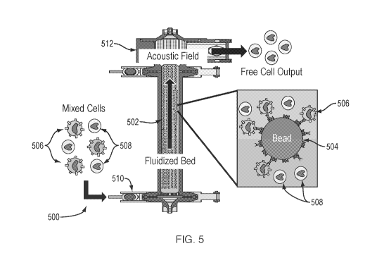
[0089] Referring to Fig. 5, a fluidized bed system 500 is illustrated. In this
example implementation, column 502 is packed with affinity beads 504, which
may be in the range of about 10% to about 30% packing where % packing
indicates the percentage of bead volume versus volume of the entire column.
Beads 504 are provided with affinity structures to bind to target cells 506.
An
acoustic transducer 512 capable of generating an acoustic field is coupled to
a
top of column 502. In operation, a mix of target cells 506 and nontargeted
cells
508 is input into column 502 via an inlet 510. As the mix of cells flows
through
column 502, target cells 506 bind with beads 504. Nontargeted cells 508 tend
not to bind with beads 504 for lack of a complementary affinity structure. As
the mixture flows through column 502 towards transducer 512, beads 504 are
free to move within the fluidized bed of column 502. As beads 504 approach
the acoustic field generated by transducer 512, they are blocked by the
acoustic
edge effect and/or being trapped in the acoustic field. In any case, beads 504
are prevented from passing to the output of column 502. As target cells 506
23
CA 03152196 2022-02-22
WO 2021/041621
PCT/US2020/048126
bind to beads 504, target cells 506 are prevented from exiting column 502
along
with the beads 504 to which they are bound. Nontargeted cells 508 are not
influenced as strongly by the acoustic field as are beads 504 and can pass
through the acoustic field and exit column 502.
[0090] This affinity technique employed with fluidized bed system 500 can be
implemented on a single-pass basis. System 500 can be configured with the
choice of beads to select for material that passes through and exits column
502,
or to select for material that is bound to the beads and retained in column
502.
The passed or retained material can be positively or negatively selected.
[0091] Referring to Fig. 6, an affinity separation process 600 is illustrated.
Process 600 includes an external incubation step where affinity beads and
cells
are combined together to obtain bead complexes. The mix of bead complexes
and uncombined material in a fluid is fed into a column 602. As the fluid mix
travels along column 602, the bead complexes are directed into column 602 by
an acoustic field generated by transducer 604. The uncombined material exits
column 602 by passing through the acoustic field. This separation step retains
the bead complexes while removing a majority of the uncombined material.
Once the bead complexes are loaded into column 602, a flush process can be
implemented with the introduction of a buffer fluid at the base of column 602.
The remaining uncombined material moves with the buffer fluid through the
acoustic field generated by transducer 604. The bead complexes also move
with the buffer fluid along column 602 but are blocked from exiting by the
acoustic field.
[0092] Process 600 offers a number of features that are advantageous for
affinity separation of materials. For example, binding of target material to
the
beads can take place externally, which also permits flexible incubation steps.
The acoustic separation provides a gentle and high throughput separation
process that quickly reduces the amount of uncombined material in mix with
bead complexes. For example, the separation process can be completed in
less than one hour. Process 600 is also flexibly scalable and can handle
processing volumes in the range of about 10mL to about 1L. In addition, all
types of beads may be used in process 600, providing significant flexibility
for
unique or custom affinity separation processes.
24
CA 03152196 2022-02-22
WO 2021/041621
PCT/US2020/048126
[0093] Referring to Fig. 7, a fluidized bed system 700 is illustrated. A
column
702 is provided, which can be implemented as any of the columns illustrated in
Figs. 4-6. In a first wash process, column 702 is loaded with affinity beads.
A
wash solution is passed through column 702 while acoustic transducer 704 is
on to generate an acoustic field near a top of column 702. The acoustic field
retains the affinity beads in column 702 while the wash solution passes
through
to wash the affinity beads. A capture process is implemented in which cellular
material is introduced into column 702. Target cellular material binds to the
affinity beads to form bead complexes and is blocked from exiting column 702
by the acoustic field generated by the acoustic transducer 704. Nontargeted
material can pass through the acoustic field and can exit column 702. After
the
capture process, a flush process is provided where fluid is introduced to
column
702 to flow the nontargeted material out of column 702. The bead complexes
are retained in column 702 against the fluid flow by the acoustic field
generated
by the acoustic transducer 704.
[0094] System 700 offers a number of advantageous features for affinity
separation processes, including internal bead binding and low shear forces
imposed on the material in column 702. The internal bead binding with low
shear forces can be important when larger beads are used due to potentially
greater binding energy that is associated with larger beads. For example, it
may take longer, or a greater amount of energy, for targeted cellular material
to
be captured by the larger beads. Lower shear forces can thus help to avoid
impeding binding with larger beads. System 700 can employ acoustic
transducer 704 to create an acoustic edge effect, which can lead to improved
throughput. For example, the processes of binding and separation can be
completed in under 2 hours. System 700 is scalable and can handle processing
volumes in the range of about 10mL to about 1L. the fluidized bed employed in
system 700 can be used with beads or with cells for the purposes of affinity
separation and/or separation alone.
[0095] Referring to Fig. 8, a cell selection system 800 is illustrated. System
800
includes a column 802 that is provided with a stirring mechanism 804. Stirring
mechanism 804 can be implemented as a stir bar near a base of column 802.
An affinity separation process can be implemented in system 800 using column
802 as a fluidized bed. Column 802 is loaded with affinity beads, for example
CA 03152196 2022-02-22
WO 2021/041621
PCT/US2020/048126
in a range of about 10% to about 30% packing. The affinity beads are washed
with the introduction of a fluid into column 802 while the acoustic field is
generated by acoustic transducer 806. The fluid exits column 802 while the
affinity beads are blocked from exiting by the acoustic field. A mix of
cellular
material is introduced into column 802 while acoustic transducer 806 generates
an acoustic field near a top of column 802. All of the cellular material is
retained
in column 802, along with the affinity beads, with the implementation of the
acoustic field. Excess fluid may pass the acoustic field and exit column 802
while the cells and affinity beads are blocked from exiting.
[0096] During the wash process and the introduction of the cellular material,
transducer 806 may be operated in different modes or with different
characteristics to, in one case, block the affinity beads from exiting during
the
wash process, and in another case, block both of the affinity beads and the
cellular material from exiting. For example, the frequency used to drive
transducer 806 may be different to retain the affinity beads than the
frequency
when both the cells and affinity beads are retained.
[0097] Once column 802 is loaded with affinity beads and cellular material,
stirring mechanism 804 can be employed to agitate column 802. The agitation
contributes to moving the affinity beads and the cellular material within
column
802. As the affinity beads and cellular material move within column 802 the
affinity binding process for targeted material can be enhanced. This
incubation
step can be implemented with no fluid flow and with transducer 806 being
unenergized.
[0098] Once the incubation/binding process is completed, the affinity
bead/targeted material complexes can be washed, and nontargeted material
can be removed from column 802. The targeted material may be separated
from the affinity beads with a solution provided to column 802 that promotes
detachment of the targeted material from the affinity beads. For example, the
solution can include enzymes (e.g., trypsin) in a buffer. For example, The
targeted material may then be removed from column 802, while the affinity
beads are retained with the acoustic field generated by the acoustic
transducer
806.
[0099] Referring to Fig. 9, an affinity selection process 900 for positive
selection
in a straight column with a single pass is illustrated. Process 900 begins
with
26
CA 03152196 2022-02-22
WO 2021/041621
PCT/US2020/048126
the loading of column 902 with affinity beads and washing the beads. Acoustic
transducer 904 generates an acoustic field near a top of column 902 during the
loading and washing processes. A mix of cellular material is then fed into
column 902. Target material is bound to the affinity beads to form bead
complexes. The nontargeted material exits column 902 through the acoustic
field. The targeted material is retained with affinity beads in column 902,
while
the nontargeted material exits column 902. The bead complexes are washed
with the introduction of a buffer into column 902. A detachment buffer is
introduced to column 902 to cause the targeted material to detach from the
affinity beads. With the acoustic field in place, the detached targeted
material
exits column 902 and is collected, while the affinity beads are retained.
[0100] Referring to Fig. 10, an affinity selection process 1000 for negative
cell
selection in a straight column with a single pass is illustrated. Process 1000
begins with the loading of column 1002 with affinity beads to a desired void
fraction. The loading process can be implemented while acoustic transducer
1004 is removed from column 1002. With acoustic transducer 1004 connected
to a top of column 1002, the affinity beads are washed with the introduction
of
a buffer. This washing process also serves to expand the bead volume to form
a fluidized bed. With acoustic transducer 1004 generating an acoustic field, a
mix of cellular material is fed into column 1002. Target material is bound to
the
affinity beads to form bead complexes. The nontargeted material exits column
1002 through the acoustic field. The targeted material is retained with the
affinity beads in column 1002, while the nontargeted material exits column
1002
and is collected as the desired product. This negative cell selection removes
the targeted material from the mix of cellular material in a single pass. The
affinity beads can be multiplexed or configured to bind with more than one
type
of targeted material, which permits multiplexed negative selection in a single
pass.
[0101] Referring to Fig. 11, a graph 1100 illustrates bead retention with an
acoustic field versus fluid inflow rate for an acoustic fluidized bed column.
As
shown in graph 1100, 100% of the beads are retained in the column as the fluid
inflow rate increases from 0 to about 10 mL per minute. As the fluid inflow
rate
increases beyond 10 mL per minute, more and more beads pass through the
acoustic field. The data presented in graph 1100 is useful to understand the
27
CA 03152196 2022-02-22
WO 2021/041621
PCT/US2020/048126
breakthrough fluid inflow rate that causes beads to pass through the acoustic
field. This test used SP Sepharose "Fast Flow" beads with an average diameter
of 90 pm and an average density of 1.033 g/cc. The terminal velocity was 52.2
cm/hr. The column parameters were: volume ¨ 40 ml, height ¨ 20 cm; and
diameter - 1.6 cm. The expanded void fraction was 70% with a starting bead
concentration of 7.86E+05 cells/ml. Operating parameters were: frequency ¨ 1
MHz and power¨ 3W.
[0102] Referring to Fig. 12, a graph 1200 illustrates total viable cells
recovered
in an acoustic affinity system versus column volumes where column volumes
indicates the amount of input to the system normalized by the volume of the
column. As shown in graph 1200, the total viable cells, in millions of cells
per
milliliter, increases significantly after about a half a column volume. This
data
shows the efficiency of binding in the acoustic affinity system. For example,
almost no unbound cells are observed during the initial half a column volume
of supplying a cellular material feed to the fluidized bed column.
[0103] Referring to Fig. 13, a graph 1300 illustrates a histogram of beads
exiting
a fluidized bed column in accordance with particle diameter. Graph 1300 shows
that at lower flowrates, small particles escape the column while larger
particles
are retained. In addition, the average size of an escaping particle increases
with flow rate.
[0104] Referring to Fig. 14, a fluidized bed system 1400 for implementing
acoustic affinity cell selection with the recirculation is illustrated. System
1400
includes a column 1402 and an acoustic transducer 1404. Column 1402
includes annular ribs 1406 that can impede the flow of fluid and force fluid
flow
toward the center of column 1402. Ribs 1406 can help prevent undesired
effects such as channeling within column 1402.
[0105] System 1400 is operated similarly to those discussed above. For
example, system 1400 may be used for positive or negative selection and can
employ different modes of operation with the acoustic transducer 1404. System
1400 illustrates the use of recirculation to improve target cell recovery, by
providing more opportunities for target cells to bind with beads in column
1402.
After the beads are loaded into column 1402 and washed, a pass 1 feed is
supplied to column 1402. The outflow of column 1402 resulting from the pass
1 feed is collected for use as a pass 2 feed. The pass 2 feed is used as the
28
CA 03152196 2022-02-22
WO 2021/041621
PCT/US2020/048126
input for a feed supply in a follow-on recirculation pass. Although not shown,
the pass 2 feed can generate an outflow that can be collected for another
follow-
on recirculation pass. Any number of recirculations can be employed. Each of
the example systems and fluidized beds discussed herein can be configured to
have multiple recirculation passes.
[0106] Referring to Fig. 15, a graph 1500 illustrates the purity (P) and
percentage recovery (R) in a fluidized bed system with a number of
recirculated
feed passes. Graph 1500 shows that purity is maintained at a high level,
greater than 90% for recirculation passes 1 and 2, and greater than 80% for
recirculation pass 3. The recovery of cells increases with each recirculation
pass, nearing 100% with the third recirculation.
[0107] Referring to Fig. 16, an example implementation of a bead with the
functionalized material is illustrated. The bead is configured to have an
affinity
for 0D3 receptors on a cell. The bead may be coated with streptavidin,
monomeric avidin, protein A, and/or anti-0D3. A biotin - anti-0D3 complex may
be used to provide the affinity target for the 0D3 receptor on the cell. The
anti-
0D3-biotin antibody may be replaced or substituted with an anti-TOR-biotin
antibody. The streptavidin coated beads can provide a greater binding surface
area than other types of coatings. For example, the streptavidin coated beads
can have a greater cell binding/cm2 ratio than other coatings. The term
coating
is used to refer to functionalized material on a surface of a bead, and may
cover
portions or all of a bead surface. Alternatively, or in addition, a portion of
a bead
may be coated with streptavidin and another portion may be coated with
another functionalized material to implement multiplexed affinity processes.
[0108] Referring to Fig. 17, a graph showing size distributions of different
types
of beads is illustrated. The y-axis is graduated in terms of percentage, while
the x-axis is graduated by size in micrometers. The graph illustrates the
different size distributions of the GE Sepharose beads and the ABT beads. The
beads are distributed over a size that is greater than the size of the cells.
The
size differential between the beads on the cells can be used as an acoustic
contrast factor to distinguish between and separate the beads and the cells.
[0109] Referring to Fig. 18, a graph illustrates binding ratios for different
types
of beads. The binding ratios are for an initial cell population of 100,000
cells.
The y-axis represents cells/ cm2 and the x-axis represents the different types
of
29
CA 03152196 2022-02-22
WO 2021/041621
PCT/US2020/048126
beads. As illustrated, the Sepharose beads, with an average size of 34 pm in
diameter, attained a binding ratio of greater than 30,000 cells/ cm2. The
Promega beads, with an average size of 65 pm in diameter, attained a binding
ratio of about 65,000 cells/ cm2. The Pluribeads, with an average size of 70
pm
in diameter, attained a binding ratio greater than the Sepharose beads, and
less than 40,000 cells/ cm2.
[0110] Referring to Fig. 19, a diagram illustrating a comparative analysis
between different affinity systems is shown. One system uses APC and anti-
CD3, while the other system uses APC, anti-biotin, biotin, and anti-CD3. As
shown in the diagram, the system including the biotin resulted in about 65%
binding, while the system without biotin resulted in about 55% binding. The
comparative implementation includes antiCD3-fluorophore vs. antiCD3-
biotin+antibiotin-fluorophore.
[0111] Referring to Fig. 20, several graphs are illustrated representing cell
count
for different antibody titration ratios. As the
graphs illustrate, the cell
populations have greater separation as the titration ratio increases.
[0112] Referring to Fig. 21, a chromatogram illustrating cell count per
milliliter
versus column volumes is shown. Column volumes referred to the amount of
fluid entrained with material that is presented to or recirculated in a
fluidized
bed. It is desirable in the fluid flow through the column to achieve plug
flow.
[0113] Referring to Fig. 22, a graph illustrating cell count in column outflow
over
time is shown. Turbidity of the column outflow correlates well with cell
concentration.
[0114] Several experimental tests for acoustic affinity cell separation were
conducted. The results of the tests are tabulated as examples below.
Example 1
[0115] Four fluidized bed platform tests were performed with different cell
concentrations (100 e6/mL and 10 e6/mL) and different capturing antibody
combinations (Anti-TCR a/b only vs Anti-TCR a/b and Anti-CD52) on the first
day of testing. The initial feed concentration (100 e6/mL and TCR a/b-
population was 74 - 78 %).
[0116] All samples were incubated with the corresponding capturing antibody
combinations listed in Table 1 in 2% BSA in PBS for 20 minutes on the IKA
roller (30rpm). Cells were washed twice with 2% BSA in PBS and finally re-
CA 03152196 2022-02-22
WO 2021/041621 PCT/US2020/048126
suspended in 10mL 2% BSA in PBS. A sample was removed for flow cytometry
and used as the initial population for tests A through D. Next, 4m1 of a 50%
solid Promega bead slurry were loaded into the fluidized bed column and
washed with 30m1 of a 2% BSA in PBS solution to remove residual ethanol and
particulates. This initial washing step was performed at a flow rate and power
of lml/min and 0.75W.
[0117] The feed cell population was then separated using the fluidized bed
unit
packed with avidin-conjugated methacrylate beads (Promega) which operated
at the following conditions; flow rate - 1mL/min and power - 0.75W. The first
fraction, denoted as the outflow, was collected after the entire sample was
loaded into the fluidized bed. A second fraction, denoted as the flush, was
collected after flushing the fluidized bed with 30m1 of a 2% BSA in PBS
solution
at 1m1/min and 0.75W. This flushing step is implemented to ensure all
uncaptured cells are recovered. Once this process was completed, the
remaining contents of the column were retrieved and collected as the third
fraction, denoted as the holdup. Samples from all three fractions were
collected
for flow cytometry. For the purposes of conducting a mass balance, the mass
and cell count for each fraction was recorded.
Table 1. Fluidized Bed (FB) platform test parameters
Dayl, Fluidized Bed (FB) test parameters
Label Antibody Bead Cell conc.
Sample volume Total cell # Bead volume TCR a/b CD52 Analytics
[x10^6/m4 [mld [x10^6] [mld [mld [mld
FB_A TCR a/b Promega 100 10 1000 2 1.5 -
Counting & Flow
FB_B TCR a/b and CD52 Promega 100 10 1000 2
1.5 0.56 Counting & Flow
FB_C TCR a/b Promega 10 10 100 2 0.15 -
Counting & Flow
FB_D TCR a/b and CD52 Promega 10 10 100 2
0.15 0.056 Counting & Flow
[0118] The purity increased by approximately 15% for all samples after
separation by the fluidized bed unit, where the initial cell population
consisted
of 76% TOR knockout cells. In tests conducted at a higher cell concentration
(100E6 cells/mL), samples A and B yielded a purity of 13% and 10% in the
outflow and 11% and 8% in the flush respectively showing a slight decrease in
purity in the second fraction. The purity in the holdup fraction was 73.2% and
68.1% for samples A and B indicating that 100% purity was not achieved. Tests
conducted at lower cell concentrations (10E6 cells/mL) yielded a higher purity
31
CA 03152196 2022-02-22
WO 2021/041621 PCT/US2020/048126
of 90.5% and 92.4% in the outflow fraction and even higher purity in the flush
fraction of 94.8% and 93.2% in samples C and D respectively. This result
showed that lower cell concentrations were better with current conditions used
with the fluidized bed unit. Overall employing the combination of anti-TCR and
anti- 0D52 as capturing antibodies did not yield significantly different
purity
compared to using anti- TCR as the sole capturing antibody.
Table 2. TCR a/b- purity and recovery from Fluidized Bed test
Day1, Fluidized Bed (FB) test results
Label TCR a/b- purity ro]
Recovery
Control Outflow Flush Hold-up [0/0]
FB A 74.50% 84.10% 83.10% 73.00% 6.70%
FB B 75.40% 83.10% 81.90% 67.50% 4.80%
FB C 78.10% 90.60% 94.80% 78.40% 33.60%
FB _D 76.30% 92.30% 93.20% 81.30% 32.90%
[0119] The total TCR- recovery for each test is equal to the sum of TCR- cells
in the flow-through and flush fractions divided by the starting TCR- cell
count
(See Eq.6 in Appendix). There are two mechanisms by which TCR- cells could
be retained in the fluidized bed system: acoustic retention and inefficient
flushing. Acoustic retention occurs when a free cell experiences a greater
force
from the acoustic field compared to the drag force exerted by the fluid flow.
This
happens at high power to flow rate ratios and can be prevented by optimizing
operating conditions. Cells also tend to disperse into the volume of the
system,
making a flush step necessary to improve recovery. The flushing step should
have a uniform velocity distribution, otherwise a large volume of buffer is
needed to recover TCR- cells as the incoming wash buffer mixes with the
fluidized bed. This type of cell retention can be reduced by increasing flush
velocity and volume and improving the fluidized bed inlet design.
[0120] For each fluidized bed test the total TCR- cell recovery can be seen in
Table 2.
[0121] The lowest recoveries were seen while testing high cell densities (100
e6/m1). Tests A and B had TCR- recoveries of 7% and 5% respectively. A
"clogging" effect in the column was observed during these tests where beads
32
CA 03152196 2022-02-22
WO 2021/041621
PCT/US2020/048126
and cells agglomerated together in very large clumps. Rather than acting as a
fluid these solid clumps caused channeling in the column and prevented cells
from escaping. It is also possible that non-specific binding occurred as the
column fouled.
[0122] Tests C and D had similar recoveries, 34% and 33%. The two tests with
e6/m1 behaved as expected but still had relatively low TCR- cell recoveries.
This is due to the low fluid velocity and inefficient flush step described
previously
and can be improved by optimizing operating conditions and improving the
fluidized bed inlet design. Changing the antibody had a minimal effect on cell
recovery.
Example 2
[0123] Four Acoustic Separator unit tests were performed with different
affinity
bead types (Promega, Dynabead, PolyStyrene 6pm and 14pm). On Day 2,
fixed antibody combination (Anti-TCR and Anti-CD52) and antibody volume of
0.15mL and 0.052mL, respectively) were used. The initial TCR a/b- population
was 77 %.
[0124] All samples were incubated with anti-TCR and anti-CD52 in 2% BSA in
PBS for 20 minutes on the IKA roller (30rpm). Cells were washed twice with 2%
BSA in PBS. A sample was removed for flow cytometry and used as the initial
population for tests L through Q. Samples were incubated with the
corresponding bead candidate listed in Table 3. for 30 minutes on the IKA
roller
(30rpm) in 10mL of 2%BSA in PBS and then separated using the Acoustic
Separator unit operated at the following conditions; flow rate - 1mL/min and
power - 0.75W. The first fraction, denoted as the outflow was collected after
the
entire sample passed through the acoustic field. A second fraction denoted as
the flush was collected after flushing the fluidized bed with 30m1 of a 2% BSA
in PBS solution. Once this process was completed, the remaining contents of
the column were retrieved and collected as the third fraction, denoted as the
holdup. Samples from all three fractions were collected for flow cytometry.
For
the purposes of conducting a mass balance, the mass and cell count for each
fraction was recorded.
33
CA 03152196 2022-02-22
WO 2021/041621 PCT/US2020/048126
Table 3. Acoustic Separator(AC) platform test parameters
Day2, Acoustic Separator (AC) parameters
Label Antibody Bead Cell
conc. Sample volume Total cell # Bead volume TCR a/b CD52 Analytics
[x10^6/mL] [x10^6]
AC_A TCR a/b and CD52 Promega 10 10
100 2 0.15 0.056 Counting & Flow
AC_B TCR a/b and CD52 Dynabead 10 10
100 0.015 0.15 0.056 Counting & Flow
AC_C TCR a/b and CD52 PS (6um) 10 10
100 0.015 0.15 0.056 Counting & Flow
AC_D TCR a/b and CD52 PS (14um) 10 10
100 0.015 0.15 0.056 Counting & Flow
[0125] The purity increased by approximately 13% for all samples after
separation by the Acoustic Separator unit, where the initial cell population
consisted of 77% TCR knockout cells. The sample incubated with Dyna beads
resulted in the highest purity of 89.4% in the outflow fraction while the
sample
incubated with Polystyrene (10 - 14pm) beads resulted in the lowest purity of
84.3%. This trend was also observed in the flush fraction where samples
incubated with Dyna beads yielded 91.1% purity and Polystyrene beads yielded
84.5% purity. The purity in all samples increased slightly from the outflow
(84.3% - 89.8%) to the flush fraction (84.6% - 91.1%).
Table 4. TCR a/b- purity and recovery from Fluidized Bed test
Day2, Acoustic Separator (AC) test results
Label TCR a/b- purity FA Recovery
Control Outflow Flush Hold-up [%]
AC A 76.20% 86.70% 86.20% 79.20%
79.90%
AC B 77.60% 89.80% 91.10% 88.90%
17.00%
AC C 77.70% 88.30% 89.40% 84.70%
26.20%
AC _D 77.40% 84.30% 84.60% 79.70%
27.10%
[0126] The total TCR- cell recoveries for each acoustic separator system test
can be seen in Table 4. In this figure it appears that the recovery is
affected by
the bead type, with 50pm Promega beads having an 80% TCR- cell recovery
and 4.5pm Dyna-beads having just 17% recovery. Both polystyrene particles
had similar recoveries, 26% and 27% for 6pm and 14pm beads respectively.
Since every test was performed with the same operating conditions, similar
recoveries were expected so this relationship should be confirmed in future
34
CA 03152196 2022-02-22
WO 2021/041621
PCT/US2020/048126
work. Like in the fluidized bed, TCR- recovery in the Acoustic Separator
system
can be increased by increasing flow velocity and by improving the inlet and
collector designs.
Example 3
[0127] Two Fluidized Bed (FB) processes and two Acoustic Separator(AS)
processes were performed. Different pump systems (Syringe pump and
peristaltic pump) were tested on the Fluidized Bed unit and two new bead
candidates were tested on the Acoustic Separator unit on the first day of
testing.
The initial feed concentration was 107 cells/mL and TCR a/b- population was
about 80%.
[0128] Sample preparation and acoustic unit operating procedures were the
same as previous examples. Briefly, feed samples for the Fluidized Bed were
incubated with biotinylated anti-TCR a/b antibody (Table 5) in 2% BSA in PBS
for 20 minutes on the IKA roller (30rpm). Cells were washed twice with 2% BSA
in PBS and finally re-suspended in 10mL 2% BSA in PBS. For the feed samples
for the Acoustic Separator unit, bead incubation was followed by antibody-cell
incubation. 1 x 10⁶ cells from each feed sample were collected separately for
flow cytometry and used as the initial population for each test.
[0129] The fluidized bed column was loaded with 2m1 Promega bead slurry
(avidin-conjugated methacrylate beads) and then washed with 30m1 of a 2%
BSA in PBS solution to remove residual ethanol and particulates. This initial
washing step was performed at 3mL/min and 2.25W. Two different pumps
(Syringe pump ¨ FB_A and Peristaltic pump ¨ FB_B) were evaluated on day 1.
The feed cell population was then separated using the fluidized bed unit
packed
with Promega beads which operated at 3m L/min and 4mL column volume. For
the Acoustic Separator unit operation, bead labeled feed were separated at the
following conditions; flow rate - 1mL/min and power - 0.75W.
[0130] For the performance evaluation, processed samples from both units
were collected and analyzed from three different fractions ¨ outflow, flush
and
holdup (Table 6). The first fraction of the processed sample, denoted as the
outflow, was collected after the entire sample was loaded into the fluidized
bed.
A second fraction, denoted as the flush, was collected after flushing the
fluidized bed with 30m1 of 2% BSA in PBS solution. This flushing step is
necessary to ensure all uncaptured cells are recovered. Once this process was
CA 03152196 2022-02-22
WO 2021/041621 PCT/US2020/048126
completed the remaining contents of the column were retrieved and collected
as the third fraction, denoted as the holdup. Samples from all three fractions
were collected for flow cytometry. The mass and cell concentration count for
each fraction was recorded for the cell recovery evaluation.
Table 5. Fluidized Bed(FB) and Acoustic Separator (AS) unit test parameters
(bead volume = 1cc, slurry volume = 4m1.
Dayl, Fluidized Bed (FB) and Acoustic Separator (AS) test, parameters
Label Antibody Bead Cell conc. Feed
volume Bead volume TCR a/b Power Flow rate Comments
[x10^6/mL] [mL] [mL] [mL] [W] [mL/min]
FB_A Anti-TCR Promega 10 10 2 0.15 2.25 3
Syringe pump
FB_B Anti-TCR Promega 10 10 2 0.15 2.25 3
Peristaltic pump
AS_C Anti-TCR PLGA 10 10 0.15 0.15 0.75 1
Syringe pump
AS_D Anti-TCR WAX 10 10 0.15 0.15 0.75 1
Syringe pump
[0131] The purity increased by approximately 11 - 12% for all samples after
separation by the Fluidized Bed unit and almost no change after separation by
the Acoustic Separator unit, where the initial cell population consisted of
80%
TOR knockout cells (Table 6). For the Fluidized Bed tests, both peristaltic
pump(FB_A) and syringe pump(FB_B) resulted in similar level of purity
(90-92%) in the flow through and flush fraction. In addition to fluidized bed
testing, two different micron sized bio-degradable particle candidates (AS_A -
PLGA and AS_B - Wax) were tested in Acoustic Separator unit.
[0132] Table 6 also shows recovery results. Fluidized Bed with peristaltic
pump
(FB_A) and syringe pump (FB_B) showed 78% and 61% of TOR - recovery,
respectively. Based on the results, FDS decided to use peristaltic pump for
upcoming platform validation. Peristaltic pump enables flexibility of further
process optimization and closed system development. Acoustic Separator for
PLGA and Wax resulted low recovery (50% and 38%, respectively).
36
CA 03152196 2022-02-22
WO 2021/041621 PCT/US2020/048126
Table 6. Fluidized Bed(FB) and Acoustic Separator (AS) unit test parameters
Day1, Fluidized Bed (FB) and Acoustic Separator (AS) test, results
Label Processed TCR a/b- rio]
Recovery
Control Flow through Flush Hold-up [0/0]
FB A 80.20% 92.24% 91.44% 86.90% 78.04%
FB B 79.10% 90.43% 91.26% 73.20% 61.37%
AS _A 80.00% 80.40% 80.10% 79.50% 49.54%
AS _B 80.60% 81.00% 83.70% 79.70% 38.49%
Example 4
[0133] Four fluidized bed unit tests were performed with different operation
procedures. The residence time of feed cells in the column was increased by
re-circulation of the processed sample or by holding samples in the column for
a longer time period. The initial feed concentration was 107 cells/mL and TOR
a/b- population was about 80 %.
[0134] The same procedure was performed for feed and initial bead loading of
the Fluidized Bed unit as in day 1. Table 7 shows four different operation
procedures, no recirculation (FB_E, no recirc.), one recirculation (FB_F, 1
recirc.), 4 recirculations (FB_G, 4 recirc.) and stop and flow (FB_H, Stop and
Flow). Specifically, in the stop and flow condition, 2.5mL of feed samples
were
loaded with (3mL/min) and flow stopped for 3min 20 sec. This procedure was
repeated until all the feed volume was loaded into the column. All the feed
cells
were held in the column by higher power condition (4.5W) for a total of 13min
205ec. Once the recirculation steps and stop and flow steps were finished, the
column was flushed with 30mL of 2% BSA solution. The processed samples
were collected and analyzed as in day 1.
37
CA 03152196 2022-02-22
WO 2021/041621 PCT/US2020/048126
Table 7. Fluidized Bed (FB) platform and Acoustic Separator (AS) unit test
parameters (bead volume = 1mI)
Day2, Fluidized Bed (FB) test, parameters
Label Antibody Bead Cell conc. Feed
volume Bead volume TCR a/b Power Flow rate Comments
[x10^6/mL] [mL] [mL] [mL] [W] [mUmin]
FB_E TCR Promega 10 10 2 0.15 2.25 3 No
recirc.
FB _F TCR Promega 10 10 2 0.15 2.25 3 1
recirc.
FB¨G TCR Promega 10 10 2 0.15 2.25 3 4
recirc.
FB¨_H TCR Promega 10 10 2 0.15 2.25 3 Stop
and Flow
[0135] The purity increased by approximately 9-18% for all samples after
separation, where the initial cell population consisted of 80% TCR knockout
cells (Table 8). One recirculation (FB_F) resulted 95.6% and 97.7% of purity
in
Flow through and Flush portion, respectively. Notably, 4 recirculations (FB_G)
showed low purity and we observed some temperature increase due to the 4
times of recirculation. The temperature rising also happened in stop and flow
condition (FB_H).
Table 8. TCR a/b- purity and recovery from Fluidized Bed and Acoustic
Separator test
Day2, Fluidized Bed (FB) test, results
Label Processed TCR a/b- [%]
Recovery
Control Flow through Flush Hold-up [0/0]
FB E 80.50% 93.16% 96.37% 73.50% 51.86%
FB F 79.80% 95.64% 97.69% 59.20% 82.64%
FB G 80.50% 89.50% 84.80% 56.10% 98.89%
FB _H 80.10% 95.11% 91.51% 73.30% 85.75%
[0136] For the TCR a/b- recovery, Recirculation and Stop and Flow condition
showed good results. Adding more recirculation steps showed better recovery
(one recirc. ¨ 82.64% and 4 recirc. 98.89%) and stop and flow condition also
resulted high recovery (85.75%).
[0137] In accordance with the present disclosure, an acoustic affinity system
is
discussed that provides a number of advantageous features. For example, the
systems and methods discussed herein can provide increased recovery and
purity for target cellular material. The systems and methods are scalable,
38
CA 03152196 2022-02-22
WO 2021/041621
PCT/US2020/048126
capable of handling a relatively wide range of material volumes. Positive and
negative selection can be implemented in accordance with the present
disclosure. Positive selection can include implementations with apheresis
products. Negative and positive selection can be implemented on a multiplexed
basis, where multiple types of cellular material can be selected in one pass.
The systems and processes discussed herein can be fully automated and can
be figured to be used with consumable components. The acoustic affinity cell
selection system can be integrated with a cellular concentrate-wash device
and/or system for downstream applications.
[0138] Gene and cell therapy shows great promise in treating life-threatening
diseases such as cancer and auto-immunity. Therapy development, e.g., stem
cell transplants or Chimeric Antigen Receptor T-cell (CAR-T) therapies for
blood cancers, may use cell selection from an initial population from blood or
apheresis products.
[0139] To develop a CAR-T therapy, peripheral blood mononuclear cells
(PBMCs) comprising T-cells, B-cells, mono-cytes, NK cells and other cells such
as basophils, neutrophils, eosinophils, dendritic cells, are isolated from
blood
or apheresis products. Prior isolation techniques include density gradient
centrifugation (physical, label-free selection) and selection based on surface
marker expression (affinity, labelled selection). These techniques can be used
to isolate CD3+ T-cells or CD4+/CD8+ subsets of the CD3+ T-cells. The T-
cells, which may number in an inclusive range of from about 500 million to
about
one billion, may be activated, transduced with a virus to express a cancer
cell
targeting Chimeric Antigen Receptor (CAR) and further expanded before final
formulation of a dosage to the patient. The formulated cell product is infused
into the same patient from whom cells were collected for an autologous therapy
or into multiple patients for an allogeneic therapy.
[0140] The above described techniques for such cell-based therapies tend to
involve elaborate, long, and costly manufacturing processes. Moreover, the
quality control processes for a final products in such CAR-T manufacture add
to the overall time, which may cumulatively two weeks and cost -$400K per
patient. The process becomes longer and more costly as finer separations into
cell sub-types are implemented. For example, animal studies strongly suggest
that using defined T-cell subsets within the CD4+ and CD8+ populations may
39
CA 03152196 2022-02-22
WO 2021/041621
PCT/US2020/048126
have therapeutic advantages such as in vivo persistence in CAR-T therapies,
whereas other combinations of T-cell subsets which include effector and
memory phenotypes can influence the T-cell therapy short term efficiency and
long term persistence. In a commercial example, Juno Therapeutics is using
defined CD4/CD8 T-cell subsets to target CD19+ B-cells to treat Non-Hodgkins
Lymphoma.
[0141] Density gradient centrifugation, one of the more popular current cell
separation techniques, is a manual, low resolution and non-scalable process.
Cell selection using magnetic-activated cell sorting (MACS), which uses
labeling via potentially cytotoxic magnetic nanoparticles, has limited
throughput. In
practice, multiple MACS cell selections are performed
sequentially (e.g. CD4+ first and CD8+ afterwards) and they tend to collect
all
the target cells. This condition means that any desired starting ratios for
CAR-
T manufacturing are manually prepared by counting each cell type obtained
from the MACS process and then mixing the right quantities of cells together
to
obtain the desired starting ratio. This process becomes more problematic given
the variability of the PBMC composition from patient to patient.
[0142] The acoustic-oriented cell selection process discussed herein offers a
number of advantages over prior cell selection techniques. The acoustic
techniques applied to cell selection discussed herein tend to create processes
that are faster, safer, e.g. less toxic, closed, cost-efficient, robust, and
better
able to perform finer sub-separations, with better quality to obtain more
accessible cell and gene therapies, including improved CAR-T cell therapies.
[0143] One cell selection technique includes the use of angled acoustic wave-
based technology for immune cell capture and elution from apheresis products.
This technique has the potential to greatly reduce cost and process time in
cell
separation and production for cell and gene therapies. The technique enables
label-free separation based on physical properties, such as density, size,
compressibility and other factors, and permits multiplexed selection of
defined
cell subsets at high throughput and low shear rates.
[0144] The fluidized bed system discussed previously can implement acoustic
affinity cell selection (AACS) cell sorting. The AACS discussed herein employs
acoustic radiation forces that are exerted on a cell for affinity labeled cell
selection at process scale, for example, at more than one million cells per
CA 03152196 2022-02-22
WO 2021/041621
PCT/US2020/048126
second. This approach to cell manipulation is scalable and nominally shear-
free. The AACS fluidized bed consists of a column containing affinity beads
which are suspended in the column due to the balance between the bottom inlet
flow drag force and the pressure generated by the acoustic standing wave. The
fluidized bed can be operated as an expanded bed system, where the beads in
the column are expanded throughout the column volume. A packed bed system
such as the MACS will always yield high shear or low flow rates due to the
narrow channels between the beads. Since the AACS fluidized bed can be
operated as an expanded bed, the shear forces are significantly lower, and
much higher flow rates can be attained. The higher flow rates and the
scalability
of this system contributes to reducing the time constraints around affinity
cell
selection in CAR-T manufacturing. For example, prior cell selection techniques
may have an eight hour process time, which is likely to compromise the
cellular
product quality. The AACS system has the potential to perform these cell
separations in less than two hours.
[0145] The AACS system can be used for CAR-T manufacturing with the
beneficial advantage of multiplexed cell selection. The system can be
configured to permit T-cell subsets to be selected at defined ratios. Prior
cell
selection systems are unable to achieve such multiplexed cell selection. For
example, a MACS system has a packed bed that consists of large beads that
get magnetized to attract the paramagnetic nanoparticles that are attached to
the affinity targeted cells. This packed column attracts all the
nanoparticles,
regardless of the actual antibody-antigen pair that is being selected, which
means that if more than one target cell type is being isolated, a sequential
labeling step may be used. The AACS system can have beads functionalized
with antibodies for different targets. The fluidized bed permits free movement
and mixture of cells and beads, while maintaining the beads in the column
using
acoustics. A ratio of beads functionalized with different antibodies may be
employed in the column, which obtains a ratio of cells with the corresponding
different antigens that are isolated, thus enabling the simultaneous,
multiplexed, selection of, for example, CD4/CD8 cells at defined ratios.
[0146] A multiplexed positive cell selection system based on AACS is discussed
herein. The multiplexed AACS works back from the desired starting cell
population, defined by total number of T-cells and the ratio of CD4 to CD8 T-
41
CA 03152196 2022-02-22
WO 2021/041621
PCT/US2020/048126
cells. Assuming that a total of 200 million T-cells are used to start a
process at
a 1:1 ratio, 100 million of both 0D4+ and 0D8+ T-cells are isolated from an
apheresis product. It may be desirable to have three times this number, for
example, 300 million of each T-cell subtype, such that there is always the
option
of re-starting the manufacturing process with the remaining cells in case of
an
instance of manufacturing failure. In practice, there is a significant
variability in
the patient's PBMC quantity and ratios of 0D4/0D8 cells obtained in an
apheresis product. The subtypes may be 5% of the total PBMCs obtained in
the apheresis bag from patients, and preferably is at least 5% of the total.
Assuming the lowest number of PBMCs in a patient's blood is 10 billion, it is
expected that there will be at least 500 million 0D4+ and 500 million 0D8+ T-
cells in every apheresis bag. As such, the total 0D4+ and 0D8+ desired cell
recovery is at least 60% (including final purity) in the AACS multiplexed cell
selection system.
[0147] Two different methods may be employed to obtain pre-determined ratios
of different cell surface marker cell types. The first method is to have
different
ratios of beads that will bind and elute the cells equally (the "bead ratio
method"). The second method consists of having a differential release
mechanism or operation for two different bead types, with a first and second
elution. A first elution buffer 1 is used to elute cell type 1, e.g., 0D4,
from bead
1 and elution buffer 2 will elute cell type 2, e.g., 0D8, from bead type 2,
where
1 and 2 are defined by the target cell surface marker, in this case 0D4 and
0D8. This second method is referred to as a differential release method.
[0148] In both methods it is preferable for the antibody to be attached to the
beads and not to the cells, although either attachment may be used. In some
circumstances, for example when a biotin-biotinylated antibodies arrangement
is used, attachment of the antibody to the cells may cause the capture of both
target cell types. The bindings used may be i) cell-biotinylated antibody
binding
followed by monomeric avidin bead binding system ("cells first") or ii)
monomeric avidin bead-biotinylated antibody binding followed by affinity cell
capture in the fluidized bed column ("beads first"). The beads first technique
is
preferred to enable multiplexed cell selections based on beads functionalized
with different antibodies. In some implementations, multiple columns (e.g., a
column for 0D4 and a column for 0D8) may be used. Other implementations
42
CA 03152196 2022-02-22
WO 2021/041621
PCT/US2020/048126
may use a single column (e.g., a 0D4/0D8 single column mixture). Different
release methods may be used depending on the implementation. For example,
serial column release may be employed in the case of multiple columns, while
a differential release method may be employed for a single column. In some
implementations, a bead-antibody linker that can be cleaved may be used. The
multiplexed cell selection AACS processes may be performed using apheresis
product T-cells (or PBMCs) with primary cells that are 0D4+ and 0D8+ cells,
or may use a mixed cell line (e.g. with two different markers) to select the
desired cell types.
[0149] Referring to Figs. 23 and 24, a process for multiplexed cell selection
is
illustrated. In Fig. 23, the acoustic field, which may be an acoustic standing
wave, is used to block the beads from exiting the column, while the sample
containing the different cellular types is applied to the column. In Fig. 24,
the
cells of the type targeted by the bead functionalization, in this case a
streptavidin ¨ biotin bond, bind with the beads to remain in the column. The
non-targeted cells pass through the acoustic field and exit the column. These
non-targeted cells can be input to a sequential column that contains beads
that
are functionalized to capture a specific cell type that is different from that
targeted with the column illustrated in Figs. 23 and 24. The cells targeted by
the beads are positively selected, and the cells that are not targeted by the
beads are negatively selected (pass through the acoustic field to be collected
outside the column).
[0150] The methods, systems, and devices discussed above are examples.
Various configurations may omit, substitute, or add various procedures or
components as appropriate. For instance, in alternative configurations, the
methods may be performed in an order different from that described, and that
various steps may be added, omitted, or combined. Also, features described
with respect to certain configurations may be combined in various other
configurations. Different aspects and elements of the configurations may be
combined in a similar manner. Also, technology evolves and, thus, many of the
elements are examples and do not limit the scope of the disclosure or claims.
[0151] Specific details are given in the description to provide a thorough
understanding of example configurations (including implementations).
However, configurations may be practiced without these specific details. For
43
CA 03152196 2022-02-22
WO 2021/041621
PCT/US2020/048126
example, well-known processes, structures, and techniques have been shown
without unnecessary detail to avoid obscuring the configurations. This
description provides example configurations only, and does not limit the
scope,
applicability, or configurations of the claims. Rather, the preceding
description
of the configurations provides a description for implementing described
techniques. Various changes may be made in the function and arrangement of
elements without departing from the spirit or scope of the disclosure.
[0152] Also, configurations may be described as a process that is depicted as
a flow diagram or block diagram. Although each may describe the operations
as a sequential process, many of the operations can be performed in parallel
or concurrently. In addition, the order of the operations may be rearranged. A
process may have additional stages or functions not included in the figure.
[0153] Having described several example configurations, various modifications,
alternative constructions, and equivalents may be used without departing from
the spirit of the disclosure. For example, the above elements may be
components of a larger system, wherein other structures or processes may take
precedence over or otherwise modify the application of the invention. Also, a
number of operations may be undertaken before, during, or after the above
elements are considered. Accordingly, the above description does not bound
the scope of the claims.
[0154] A statement that a value exceeds (or is more than) a first threshold
value
is equivalent to a statement that the value meets or exceeds a second
threshold
value that is slightly greater than the first threshold value, e.g., the
second
threshold value being one value higher than the first threshold value in the
resolution of a relevant system. A statement that a value is less than (or is
within) a first threshold value is equivalent to a statement that the value is
less
than or equal to a second threshold value that is slightly lower than the
first
threshold value, e.g., the second threshold value being one value lower than
the first threshold value in the resolution of the relevant system.
44