Note: Descriptions are shown in the official language in which they were submitted.
CA 03152215 2022-02-22
WO 2021/072132
PCT/US2020/054864
CASSETTE FOR DISPENSING PLEATED TUBING
CROSS REFERENCE TO RELATED APPLICATIONS
[0001] The subject application claims priority to U. S. Non-provisional
application serial number 17/066,349 filed October 8, 2020, entitled
"CASSETTE FOR DISPENSING PLEATED TUBING" which is a continuation-
in-part application that incorporates and claims the benefit of the filing
date of
U.S. Provisional Patent Application Serial No. 62/912,567, entitled
"CASSETTE FOR DISPENSING PLEATED TUBING" filed October 8, 2019.
Further, the subject application, via the afore-mentioned continuation-in-part
U.S. Patent Application Serial No. 17/066,349, filed October 8, 2020, claims
the benefit of priority to the filing date of U.S. Patent Application Serial
No.
16/542,015, entitled "CASSETTE FOR DISPENSING PLEATED TUBING"
filed August 15, 2019; and U.S. Patent Application Serial No. 16/041,689,
entitled "CASSETTE FOR DISPENSING PLEATED TUBING" filed July 20,
2018, now U.S. Patent 10,435,235; and U.S. Patent Application Serial No.
14/939,588, entitled "CASETTE FOR DISPENSING PLEATED TUBING" filed
November 12, 2015, now U.S. Patent 10,053,282; and U.S. Provisional
Patent Application Serial No. 62/078,915, entitled "CASSETTE FOR
DISPENSING PLEATED TUBING" filed November 12, 2014; and U.S. Patent
Application Serial No. 14/736,192, entitled "CASSETTE FOR DISPENSING
PLEATED TUBING" filed June 10, 2015; and U.S. Patent Application Serial
No. 13/688,139, entitled "CASSETTE FOR DISPENSING PLEATED TUBING"
filed November 28, 2012, now U.S. Patent 9,085,404; and U.S. Design Patent
Application Serial No. 29/435,445, entitled "CASSETTE" filed October 24,
1
CA 03152215 2022-02-22
WO 2021/072132
PCT/US2020/054864
2012, now U.S. Patent D695,541; the entireties of all which are listed above
and incorporated herein by reference.
TECHNICAL FIELD
[0002] The subject disclosure relates to a cassette used for dispensing
pleated tubing. More specifically, to a cassette capable of storing a pleated
tubing and adapted for use within a disposal container to collect waste
refuse.
BACKGROUND
[0003] Various refillable cassettes have been provided for the disposal
of waste material. Conventional dispensers typically require cumbersome
techniques overcome by the disclosure below. Despite the ineffectiveness of
these conventional attempts to provide a storage cassette, a need exists for a
low cost, efficient storage container that can be conveniently assembled.
BRIEF DESCRIPTION OF THE DRAWINGS
[0004] Various exemplary embodiments of this disclosure will be
described in detail, wherein like reference numerals refer to identical or
similar
components or steps, with reference to the following figures, wherein:
[0005] FIG. 1 illustrates an upper perspective view of an exemplary
cassette according to the subject disclosure.
[0006] FIG. 1A shows an alternative upper perspective view of a
cassette with a different engagement groove configuration.
[0007] FIG. 2 depicts an exploded upper perspective view of an annular
cover and annular body of the cassette according to the subject disclosure.
2
CA 03152215 2022-02-22
WO 2021/072132
PCT/US2020/054864
[0008] FIG. 3 illustrates a lower perspective view of the cassette.
[0009] FIG. 4 depicts an exploded lower perspective view of the
annular cover and annular body of the cassette.
[0010] FIG. 4A depicts a partial exploded lower perspective view of a
section of the annular cover as shown in FIG. 4.
[0011] FIG. 5 shows a side view of the cassette.
[0012] FIG. 6 illustrates a bottom view of the cassette.
[0013] FIG. 7 depicts a top view of the cassette.
[0014] FIG. 8 illustrates a cross section side view of the annular cover
and annular body of the cassette at through holes of the annular cover about
line A-A in FIG. 7.
[0015] FIG. 9 depicts a cross section side view of the annular cover
and annular body of the cassette at an access hole and recessed plateau of
the annular cover about line B-B in FIG. 7
[0016] FIG. 10 shows a cross section side view of the annular cover
and annular body of the cassette at an upper horizontal wall about line C-C in
FIG. 7.
[0017] FIG. 11 illustrates a partial cross section side view of the
annular
cover and annular body of the cassette as shown in FIG. 8.
[0018] FIG. 12 depicts a partial cross section side view of the annular
cover and annular body of the cassette as shown in FIG. 9.
[0019] FIG. 13 shows an exploded cross section side view of the
annular cover and annular body of the cassette.
[0020] FIG. 14 illustrates a cross section view of the cassette having a
flexible tubing disposed therein.
3
CA 03152215 2022-02-22
WO 2021/072132
PCT/US2020/054864
[0021] FIG. 15 depicts a top perspective view of an alternate exemplary
embodiment of the cassette.
[0022] FIG. 15A illustrates a cross section view of the cassette fitted
with the annular cover and having a flexible tubing disposed therein.
[0023] FIG. 15B illustrates a top view of the cassette fitted with the
annular cover.
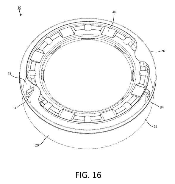
[0024] FIG. 16 depicts a second top perspective view of the cassette
shown in FIG. 15.
[0025] FIG. 17 shows a third top perspective view of the cassette from
FIG. 15 without an annular cover or pleated flexible tubing inside.
[0026] FIG. 18 illustrates a partial top perspective view of the
cassette
from FIG. 17 from an alternate viewing angle.
[0027] FIG. 19 shows a bottom view of the cassette from FIG. 17.
[0028] FIG. 20 illustrates a side perspective of the cassette from FIG.
17 that shows the bottom of the cassette.
[0029] FIG. 21 shows a cross-section view of the cassette about line A-
A in FIG. 19.
[0030] FIG. 22 is an exploded view of the cassette shown in FIG. 21.
[0031] FIG. 23 shows a cross-section view of the cassette about line B-
B in FIG. 19.
[0032] FIG. 24 is an exploded view of the cassette shown in FIG. 23.
[0033] FIG. 25 is an exploded view of the cassette shown in FIG. 20.
[0034] FIG. 26 is an exploded view of the cassette shown in FIG. 19.
[0035] FIG. 27 is an exploded view of the cassette shown in FIG. 17.
[0036] FIG. 28 is an exploded view of the cassette shown in FIG. 18.
4
CA 03152215 2022-02-22
WO 2021/072132
PCT/US2020/054864
[0037] FIG. 29 is a top perspective view of the inside of a
complementary waste container.
[0038] FIG. 30 is a top view of the empty cassette of FIG. 17 installed
in the complementary waste container.
[0039] FIG. 31 is an exploded top view of the cassette of FIG. 17 and a
mating adapter ring of the complementary waste container.
[0040] FIG. 32 is an exploded side view of the cassette of FIG. 17 and
the mating adapter ring of FIG. 31.
[0041] FIG. 33 is a side view of the cassette of FIG. 17 mated with the
adapter ring of FIGS 31-32.
[0042] FIG. 34 is a top view of the mated cassette and adapter ring of
FIG. 33.
[0043] FIG. 34A is a cross section of the cassette fitted with the
annular
cover and mated with the adapter ring.
[0044] FIG. 34B is a top view of the cassette fitted with the annular
cover and installed on the adapter ring.
[0045] FIG. 35 is a top perspective view of a cassette with tubing and
an annular cover installed in the complementary waste container.
DETAILED DESCRIPTION
[0046] Particular embodiments of the present invention will now be
described in greater detail with reference to the figures.
[0047] FIGS. 1-4 illustrate upper and lower perspective and exploded
perspective views of an exemplary cassette 10 according to this subject
disclosure.
CA 03152215 2022-02-22
WO 2021/072132
PCT/US2020/054864
[0048] FIGS. 1-4 show the cassette 10 is comprised of a lower annular
body 20 having a generally U-shaped cross-section compartment and an
annular cover 40 that extends over a portion of the U-shaped channel cross-
section compartment. An opening 58 is provided between an outer concentric
edge 49 of the annular cover 40 and an upper end 26 of an outer wall 24 of
the lower annular body 20. The annular cover 40 is attached to the lower
annular body 20 at a central cylindrical core 27, as will be discussed in
greater
detail below.
[0049] FIGS. 2 and 13 illustrate an upper view of the cassette 10
having the annular cover 40. The annular cover 40 generally has an inner
cylindrical wall 41 and upper horizontal wall 46. The annular cover 40 may
have at least one recessed plateau 50 and at least one through hole 56
disposed in the upper horizontal wall 46. The annular cover 40 may also have
at least one engagement groove 70.
[0050] FIG. 2 shows that the annular cover 40 may be constructed with
a series of vertical, angled and horizontal walls from the inner cylindrical
wall
41 to the outer concentric edge 49 (as shown in greater detail in the cross-
section views in FIGS. 11-12). The inner cylindrical wall 41 is connected to a
first horizontal wall 42, which radially extends outward and terminates at a
second cylindrical wall 43. The second cylindrical wall 43 is connected to a
second horizontal wall 44, which radially extends outward and terminates at
an upward angular wall 45. The upward angular wall 45 is connected to the
upper horizontal wall 46, which terminates at a downward angular wall 47.
The downward angular wall 47 extends downward for a predetermined
6
CA 03152215 2022-02-22
WO 2021/072132
PCT/US2020/054864
distance and then curves upward at a curved portion 48 and is connected to
the outer concentric edge 49 that extends upward to an edge 49a.
[0051] The inner cylindrical wall 41, first horizontal wall 42, second
cylindrical wall 43, second horizontal wall 44, upward angular wall 45, upper
horizontal wall 46, downward angular wall 47, curved portion 48 and outer
concentric edge 49 collectively may form the annular cover 40. It is to be
understood, however, that the annular cover 40 may be constructed by any
combination of the aforementioned segments to provide a cover of the U-
shaped channel cross-section compartment.
[0052] FIG. 3 depicts a lower perspective view of the cassette 10. The
lower annular body 20 includes an inner wall 21 connected to an angular wall
22. The angular wall 22 is connected to a bottom wall 23, which is connected
to an outer wall 24. The outer wall 24 terminates at an upper end 26 thereof.
The inner wall 21, angular wall 22, bottom wall 23 and outer wall 24
collectively form the U-shaped channel cross-section of a housing into which
a pack 82 of a pleated flexible tubing 80 is received, as shown in FIG. 14.
[0053] The lower configuration of the U-shaped channel cross-section
and/or the angular configuration taken by the angular wall 22 may take a
variety of different suitable angles in order to allow air to escape from
below
during the packing of the flexible tubing 80 into the lower annular body 20 as
a
packed tubing 82 as shown in FIG. 14 and described in more detail later. For
example, the angular wall may be directly connected between the outer wall
24 and the inner wall 21, without the need for a bottom wall 23.
[0054] FIG. 3 illustrates the bottom wall 23 of the annular body 20 may
also have a bottom lip 31, a plurality of concentric downward projections 32
7
CA 03152215 2022-02-22
WO 2021/072132
PCT/US2020/054864
and a plurality of apertures 34. The bottom lip 31 may be an extension of the
outer wall 24 which extends past the bottom wall 23. The bottom lip 31 and
downward projections 32 may provide an alignment feature for stacking
multiple cassettes 10. A diameter of the bottom lip 31 may be sized such that
when a first cassette 10 is stacked on the top of a second cassette 10, either
the inside or outside face of the bottom lip 31 will nest the upper end 26 of
the
annular body 20. Furthermore, the concentric downward projections 32 may
also provide a nesting function such that, the upper end 26 of the second
cassette 10 is nested in between the bottom lip 31 and the concentric
downward projections 32 or is nested inside the downward projections 32.
[0055] FIGS. 3-6 illustrate the plurality of apertures 34 that may be
disposed in a radial configuration in the lower end of the annular body 20. As
shown, the apertures 34 may be elongated, radially extending inwardly
lengthwise from a first end 34a disposed in the bottom wall 23, to a second
end 34b inwardly extending adjacent to the intersection of the angular wall 22
and the inner wall 21. The apertures 34 may be cut into the angular wall 22
and the bottom wall 23 and disposed concentrically about in a radial pattern.
[0056] The apertures 34 provide various advantages. First, during
installation of the air-tight packing of the flexible packed tubing 82 into
the U-
shaped lower annular body 20, the various apertures 34 serve as vent holes
allowing air trapped below the packed tubing 82 to vent out of the lower
annular body 20 through the apertures 34. The venting provided by the
various apertures 34 allow the packed tubing 82 to be compressed tightly as a
pleated mass within the U-shaped lower annular body 20 without air
interfering with the volume within the lower annular body 20 that could
8
CA 03152215 2022-02-22
WO 2021/072132
PCT/US2020/054864
otherwise be filled by the packed tubing 82. As a result, no air is trapped
below the packed tubing 82 thereby allowing a tighter pack to be obtained so
that more of the flexible tubing 80 in the compressed packed tubing 82 state
can be stored within the lower annular body 20 during assembly of the tubing
80 into the cassette 10. It is understood that the aperture 34 may be
constructed into any one, or more, of the various walls 21, 22, 23, 24, or the
like.
[0057] Another significant advantage to the apertures 34 is the ability
to
control the rotation of the cassette 10. The apertures 34 may function as key
holes into which a mating key of a rotation mechanism can be used to control
the rotation of the cassette 10 during operation of a unit (such as a waste
receptacle) into which the cassette 10 may be placed and used. That is, a
key may be aligned to mate with at least one of the apertures 34. The key
may engage any portion of the aperture 34 on any wall 21, 22, 23, 24 surface
and cause the cassette 10 to rotate, or prevent the cassette 10 from rotating
by arresting the movement of the cassette 10.
[0058] Although the apertures 34 are shown as equidistant symmetric
elongated rectangular slots extending across the angular wall 22 and the
inner wall 21, it is possible to vary the number of apertures 34, their
placement, the size and/or shape of the various apertures 34 to any number,
size, symmetry or shape according to this subject disclosure. Likewise, is it
also possible to extend the aperture 34 into the outer wall 24, or
alternatively
provide the apertures 34 on any one, or more, of the inner wall 21, the
angular
wall 22, the bottom wall 23 or the outer wall 24.
9
CA 03152215 2022-02-22
WO 2021/072132
PCT/US2020/054864
[0059] FIGS. 4 and 4A depict an exploded and enlarged lower
perspective view of the annular cover 40 and annular body 20 of the cassette
10. An inner surface of the inner cylindrical wall 41 may have a projection 52
which engages the annular body 20 to attach the annular cover 40 to the
annular body 20, as will be discussed in greater detail below.
[0060] The annular cover 40 may also have a series of reinforcing
bridges 36 along an underside thereof. An axis of each reinforcing bridge 36
may extend outward radially from a center of the annular cover 40. The
reinforcing bridges may span from the inner cylindrical wall 41 to the outer
concentric edge 49, or any portion thereof. The reinforcing bridges 36
structurally support the annular cover 40 to retain its shape as the flexible
tubing 80 is pulled through the opening 58 over and through the center of the
cassette 10.
[0061] FIGS. 7-13 depict various top views of the lower annular body
20 and the annular cover 40. The annular cover 40 is disc shape and has a
central through hole defined by an inner cylindrical wall 41. The inner
cylindrical wall 41 extends upward to a first horizontal wall 42. The first
horizontal wall 42 extends from a first end inward to a second cylindrical
wall
43. The second cylindrical wall 43 extends upward to a second horizontal
wall 44 that is elevated above the first horizontal wall 42. At the lower end
of
the second cylindrical wall 43 a retaining flange or concentric shoulder 43a,
43b is formed that extends slightly below the lower surface of the first
horizontal wall 42. The second horizontal wall 44 extends radially outward to
an upper angular wall 45. The upper angular wall 45 extends radially upward
and outward at an angle to an upper horizontal wall 46. The upper horizontal
CA 03152215 2022-02-22
WO 2021/072132
PCT/US2020/054864
wall 46 extends radially outward to a downward angular wall 47. The
downward angular wall 47 extends radially downward from a first end to a
curved portion 48. The curved portion 48 has a slight u-shape that returns the
shape of the annular cover back upward into an outer concentric edge or wall
49.
[0062] The annular cover 40 is attached to the lower annular body 20 at
an annular downturned lip 28 provided at a top edge 21a of the inner
concentric wall 21 defining the central cylindrical core 27. The downward
turned lip 28 constructed at the top edge 21a of the central cylindrical core
27
is nestled within a cup shaped structure defined by the inner cylindrical wall
41, the first horizontal wall 42 and the concentric shoulder 43a, 43b disposed
at the bottom of the second cylindrical wall 43. As shown in FIGS. 11-12, the
concentric shoulders 43a, 43b extend radially around and captivates the top
edge 21a of the inner concentric wall 21 to secure the annular cover 40 to the
lower annular body 20.
[0063] The shorter concentric shoulder 43a may be extended
intermittently and constructed with intermittent extending flanges 43b or
return
walls, such as shown in exploded view in FIG. 4A. The advantage of
providing the intermittent extending flanges 43b is to be able to more
securely
captivate and secure the top edge 21a of the inner concentric wall 21 within
the cup shaped structure defined by the inner cylindrical wall 41, the first
horizontal wall 42 and the concentric shoulder 43a, 43b disposed at the
bottom of the second cylindrical wall 43. The intermittent extending flanges
43b may extend to, or at least beyond the width of the annular downturned lip
28 disposed at the top edge 21a of the inner wall 21. The intermittent
11
CA 03152215 2022-02-22
WO 2021/072132
PCT/US2020/054864
extending flange 43b may extend to at least the height of the protrusion 52b
disposed on the inside of the inner cylindrical wall 41.
[0064] The grooves 70 are adapted to receive an indexing mechanism
to manipulate the orientation of the cassette 10. For example, a user can
manually use the grooves to engage with their fingers to manually twist the
annular cover 40 into a desired position. The advantage to providing this
feature is to manually rotate the cassette 10 via the top of the lower annular
body 20.
[0065] By way of example shown in FIG. 1A, the construction of the
grooves 70, 70a may take a variety of different sizes, shapes and/or
configurations according to this subject disclosure. The outer edge surface of
the grooves 72 may be constructed of a material and/or shape having a low
coefficient of friction so that the tubing pulled over those surfaces is not
torn,
frayed or fatigued by a sharp corner of edge. Likewise, the annular cover 40
may be constructed without the grooves 70, 70a.
[0066] A plurality of apertures or through holes 56 may be provided on
the top of the annular cover 40 for orientation purposes. Furthermore, the
through holes 56 may be provided to allow aeration of a deodorant integrated
with the material composition of the tubing material. The aeration through
holes 56 can counteract any foul odor in the vicinity of the cassette 10,
particular when the cassette 10 used in a waste disposal container or unit.
[0067] A plurality of adjacent elevated bosses and recessed plateaus
may also be constructed around the upper surface of the annular cover 40.
The elevated bosses and recessed plateaus are constructed by a plurality of
recessed plateaus being straddled by elevated ledges 51 that support various
12
CA 03152215 2022-02-22
WO 2021/072132
PCT/US2020/054864
upper horizontal walls 46 forming a step-like configuration about the top end
of the annular cover 40. This construction has further advantages in
permitting the cassette 10 to be rotated about the upper surface end of the
annular cover 40.
[0068] As shown in FIGS. 11-12, in place, the annular cover 40 and the
lower annular body 20 are lockingly engaged to one another as described
above. To prevent the annular cover 40 from being disconnected from within
the expanded inner wall 21 of the lower annular body 20, the annular cover 40
is lowered and positioned within an annular downturned lip 28 of the inner
wall
21 of the annular body 20 so that a peripheral edge 28a of the lip 28 slides
past a ramp 52a of the protrusion 52. As the peripheral edge 28a slides along
the ramp 52a, the inner wall 21 will deflect outward away from the center of
the annular body 20 and against the concentric shoulders 43a, 43b. When
the peripheral edge 28a completely slides along the ramp 52a, it will snap
inward and rest above a locking shelf 52b and against the concentric
shoulders 43a, 43b as shown in FIGS. 11-12.
[0069] The peripheral edge 28a of the annular downturned lip 28 is
then locked against the locking shelf 52b of the projection 52. The projection
52 functions as a detent and the concentric shoulders 43a, 43b act as a
captivating stop so that the annular cover 40 is mechanically arrested and
cannot be undesirably lifted or raised off of the lower annular body 20 after
the
peripheral edge 28a has been securely mounted against the locking shelf 52b
and the concentric shoulders 43a, 43b. In use, the flexible tubing 82 disposed
within the cassette 10 is withdrawn with sufficient force upward from within
the
u-shaped lower annular body 20 and then over and downward over the
13
CA 03152215 2022-02-22
WO 2021/072132
PCT/US2020/054864
annular cover 40 and into the cylindrical core 27 to cause the cassette to be
jostled within the container it is situated. Unlike conventional designs
before,
the socket connection of this subject disclosure between the u-shaped lower
annular body 20 and the annular cover 40 is sufficiently secure to prevent the
shape of the cassette to be warped and the annular cover 40 disengaged
from the lower annular body 20.
[0070] Access holes 54 are disposed in the first horizontal wall 42. The
access holes 54 are provided to allow visual alignment of the top edge 21 of
the annular downturned lip 28 into the socket area constructed by the
concentric shoulders 43a, 43b, the first horizontal wall 42, the inner
horizontal
wall 41 and the locking flange 52.
[0071] FIG. 14 depicts the tubing 80 shown as a packed tubing 82
disposed in the U-shaped channel cross-section of the lower annular body 20.
The packed tubing 82 is adapted to be received and pulled upward from
within the U-shaped channel, through the opening 58, up and over the outer
concentric edge 49, across the annular cover 40, and downward through the
central cylindrical core 27 opening. The tubing 80 may be made from a
variety of different materials. The tubing 80 may be made of various
compositions and may also be scented.
[0072] FIGS. 15-35 depict an alternate exemplary embodiment of the
cassette 10 for dispensing pleated tubing. As shown in FIGS. 15-16, the
cassette 10 is fitted with an annular cover 40 that attaches to the lower
annular body 20. The lower annular body 20 has a lower closed channel
cross-section compartment comprising an inner wall 21 connected to a bottom
wall 23 (shown in FIGS. 17 and 20), which is connected to an outer wall 24.
14
CA 03152215 2022-02-22
WO 2021/072132
PCT/US2020/054864
The outer wall 24 terminates at an upper end 26 thereof. The inner wall 21,
bottom wall 23 and outer wall 24 collectively form the lower closed channel
cross-section of a housing into which a pack 82 of a pleated flexible tubing
80
is received. FIGS. 15-18 show various tilted perspective views of the cassette
with and without the annular cover 40. Two of a plurality of apertures 34
are shown disposed in the bottom of the lower annular body 20. In tilted
perspective view FIG. 15, the apertures 34 are shown from an outer surface
view of inner wall 21. In tilted perspective views FIGS. 16-18, the apertures
34 are illustrated from within the lower annular body 20.
[0073] FIG. 15A is a cross section view of the cassette 10 fitted with
the
annular cover 40 and containing the pack 82 of the pleated flexible tubing 80
in the lower annular body 20. The outer wall 24, bottom wall 23 and inner wall
form the lower closed channel cross-section compartment that houses the
pleated flexible tubing 80. The outer wall 24 terminates at an upper limit at
the upper end 26 of the lower annular body 20. The cross-section is taken
through two of the plurality of apertures 34, while a third aperture 34 is
also
shown.
[0074] FIG. 15B is a top view of the cassette 10 fitted with the annular
cover 40. The annular cover 40 is secured to the lower annular body 20.
[0075] FIG. 17 is a top perspective view of the cassette 10 without the
annular cover 40 or the pleated flexible tubing 80 that is housed in the
internal
compartment formed by the lower annular body 20. The plurality of apertures
34 in the lower annular body 20 may be elongated, radially extending inwardly
from a first end 34a disposed in the bottom wall 23, to a second end 34b
inwardly extending into the inner wall 21. FIG. 18 illustrates a partial top
CA 03152215 2022-02-22
WO 2021/072132
PCT/US2020/054864
perspective view of the cassette 10 from an alternate viewing angle that
shows the plurality of apertures 34 disposed partially inside and outside of
the
inner wall 21.
[0076] FIG. 19 is a bottom view of the cassette 10. In this embodiment,
there are four apertures 34 set 90 degrees from each other. However, it is
contemplated that a different number of apertures 34, offset by different
measures of degree may be adopted. For example, there could be three
apertures 34 offset at 120 degrees, or the apertures 34 could be offset from
one another in a non-symmetrical pattern.
[0077] FIG. 20 depicts a side perspective of the cassette 10 that shows
the bottom of the cassette 10. The bottom wall of the annular body 20 may
have a bottom lip 31, a plurality of concentric downward projections 32 and a
plurality of apertures 34. The bottom lip 31 may be an extension of the outer
wall 24 which extends past the bottom wall 23. The bottom lip 31 may be
used for stacking and storing more than one cassette 10. The concentric
downward projections 32 may also be used to orient and secure more than
one cassette 10 when stacking or storing the cassettes 10. The concentric
downward projections 32 also add structural support to the bottom wall 23 of
the cassette 10. This added structural support is especially useful when
loading the pleated flexible tubing 80 into the cassette 10.
[0078] As shown in FIG. 20, each individual aperture 34e has a gusset
shape structure. That is, each individual aperture 34e has a first aperture
sidewall 135, a second aperture sidewall 136 extending between the bottom
wall 23 and the inner wall 21. A rear aperture wall 138 is disposed at a first
end 34a of the aperture 34e and connects the first aperture sidewall 135 and
16
CA 03152215 2022-02-22
WO 2021/072132
PCT/US2020/054864
the second aperture sidewall 136 at the first end 34a. The first aperture
sidewall 135 and second aperture sidewall 136 extend from the first end 34a
of the aperture 34e to a second end 34b of the aperture 34e. In the
embodiment shown, the first end 34a of the aperture 34e is disposed in, and
extending from the bottom wall 23 inward into the annular body 20. The
second end 34b of the aperture 34 is disposed in the inner wall 21. However,
it is contemplated that the gusset structure of the aperture 34 may be
arranged in a variety of different positions. That is, the first end 34a and
second end 34b may be located entirely in either the outer wall 24, the bottom
wall 23, the inner wall 21 or any combination thereof. An advantage of the
aperture 34 having a gusset shape is that alignment and positioning of the
cassette 10 within the waste container 150 is much easier to obtain as will be
described in more detail later.
[0079] FIG. 21 is a cross-section view of the cassette 10 about line A-A
in FIG. 19. The generally U-shaped compartment of the lower annular body
20 is comprised of the inner wall 21, bottom wall 23 and outer wall 24. Two of
the plurality of apertures 34 extending to the second end 34b are shown
disposed in the inner wall 21. FIG. 22 is an exploded view of the cassette
shown in FIG. 21 that provides more detail of the bottom lip 31 and upper end
26 of the outer wall 24.
[0080] FIG. 23 is a cross-section view of the cassette about line B-B in
FIG. 19. This cross-section is taken through two of the plurality of apertures
34. FIG. 24 is an exploded view of the cassette 10 shown in FIG. 23 that
partially shows the architecture of a single aperture 34e. The rear aperture
wall 138 is disposed on the first end 34a of the aperture 34e. The first
17
CA 03152215 2022-02-22
WO 2021/072132
PCT/US2020/054864
aperture sidewall 135 and second aperture sidewall 136 extend from the first
end 34a of the aperture 34e to the second end 34b of the aperture 34e. The
rear aperture wall 138 may be disposed deeper towards the outer wall 24, or
shallower towards the inner wall 21. The depth of the rear aperture wall 138
and the height of the first and second aperture sidewalls 135,136 determine
the angle of the opening of the aperture 34e. The width of the bottom wall 23
affects the overall shape of the plurality of apertures 34. It is contemplated
that the first and second aperture sidewalls 135, 136 could be taller or
shorter,
and the rear aperture wall 138 deeper or shallower relative to inner wall 21.
[0081] FIGS. 25-28 show exploded views of the aperture 34e from
several different viewing angles. FIG. 25 shows an aperture 34e from the
perspective of one looking down at the bottom wall 23 of the cassette 10.
From this angle it is possible to see a closer view of the plurality
concentric
downward projections 32 disposed on the bottom wall 23. The interior of the
second aperture sidewall 135 and the rear aperture wall 138 are also shown.
[0082] FIG. 26 is an exploded view of the cassette 10 from FIG. 19
looking down on the bottom of the cassette 10. The contour of the aperture
34e is shown. The rear aperture wall 138 is closest to the outer wall 24 at a
first end 34a of the aperture 34e and connected by the first and second
aperture sidewalls 135, 136 to a second end 34b disposed in the inner wall
21. In this embodiment the rear aperture wall 138 is wider than the second
end 34b of the aperture 34e such that the lines of the first and second
aperture sidewalls 135, 136 would bisect if continued into the central
cylindrical core 27. However, it is contemplated that the shape of the
aperture
34e could adopt different configurations such that the lines of the first and
18
CA 03152215 2022-02-22
WO 2021/072132
PCT/US2020/054864
second apertures 135, 136 are parallel, or more acute or obtuse relative to
the
length of the rear aperture wall 138.
[0083] FIG. 27 is an exploded view of the cassette 10 shown in FIG. 17
looking down into the inside of the lower annular body 20 of an empty
cassette 10. This angle shows the exterior of the first aperture sidewall 135
and the interior of the second aperture sidewall 136. The top edge of the rear
aperture wall 138 is also shown.
[0084] FIG. 28 is an exploded view of the cassette 10 from FIG. 18 that
shows the exterior of the first aperture sidewall 135, the interior of the
rear
aperture wall 138 and the interior of the second aperture sidewall 136. In
this
embodiment, the shape of the first and second aperture sidewalls 135, 136
are quadrilateral. However, it is contemplated that the first and second
aperture sidewalls 135, 136 may have rounded edges, parallel lines or more
or less sides depending on the configuration of the complementary alignment
projections 161 of the waste container 150. Alternatively, the apertures may
be substantially circular, semi-circular, elliptical, triangular, crescent-
shaped,
T-shaped, V-shaped, or the like, with one or more walls corresponding to the
shape.
[0085] FIG. 29 shows the complementary adapter ring 160 disposed in
the interior of a waste container 150. The adapter ring 160 is fitted with
alignment projections 161 that mate with the plurality of apertures 34 of the
cassette 10. To accommodate the design of this particular waste container
150, which has four alignment projections 161 offset at 90 degrees around a
central axis 150A of the waste container 150, the complementary cassette 10
has four apertures 34. The alignment projections 161, and the corresponding
19
CA 03152215 2022-02-22
WO 2021/072132
PCT/US2020/054864
apertures 34 in the cassette 10, control, or prevent, the rotation of the
cassette 10.
[0086] The internal architecture of the plurality of apertures 34 in a
gusset shape is optimized for the structural integrity of the cassette 10. The
first aperture sidewall 135, second aperture sidewall 136 and rear aperture
sidewall 138 help locate the alignment projections 161 when installing the
cassette. The first and second aperture sidewalls 135, 136 provide structural
support against the alignment projections 161 during rotation or when
preventing rotation. The first aperture sidewall 135, the second aperture
sidewall 136 and the rear aperture sidewall 138 also elevate the pleated
flexible tubing 80 accumulated within the lower annular body 20 away from
the outer surface of the lower annular body 20. This elevation in the walls
135, 136, 138 of the aperture 34 is beneficial in substantially reducing the
interaction or interference with the alignment projections 161 that are
aligned
with and inserted into the apertures 34 such as shown in FIG. 33. Thus, the
alignment projections 161 can easily be aligned and registered within the
apertures 34. This elevated construction also helps facilitate the loading of
the pleated flexible tubing 80 into the cassette 10 and the removal of the
pleated flexible tubing 80 during use.
[0087] FIG. 30 shows the empty cassette 10 from FIG. 17 installed in
the waste container 150. The alignment projections 161 mate with the
plurality of apertures 34 located in the bottom of the cassette 10. Once
installed, the motion of the cassette 10 is determined by the rotation, or
lack
thereof, of the adapter ring 160. The cassette 10 is installed flush against
the
adapter ring 160 with the alignment projections 161 extending through the
CA 03152215 2022-02-22
WO 2021/072132
PCT/US2020/054864
plurality of apertures 34 of the cassette 10. As shown in FIGS. 15-35, the
plurality of apertures 34 provide an open through-hole from the outside of the
cassette that opens into the interior space of the annular body 20.
[0088] However, it is contemplated that the plurality of apertures 34
may not open into the interior of the lower annular body 20 and each
individual aperture 34e may also have an upper aperture wall 139 (not
shown). The upper aperture wall 139 in each of the plurality of apertures 34
would surround the top of the alignment projections 161 and prevent the
alignment projections 161 from protruding into the internal cavity of the
lower
annular body 20 as they do with the open through-hole design shown in FIGS.
15-35.
[0089] FIG. 31 is an exploded view of the empty lower annular body 20
from FIG. 17 and the mating adapter ring 160 of a complementary waste
container 150. The alignment projections 161 are lined up with the plurality
of
apertures 34 disposed in the bottom of the lower annular body 20. When the
cassette 10 is lowered onto the adapter ring 160 the plurality of apertures 34
may function as key holes into which a mating key or the alignment
projections 161 can be used to control the positioning and/or rotation of the
cassette 10 during operation of a unit (such as a waste receptacle) into which
the cassette 10 may be placed and used. The alignment projection 161 may
be adapted to engage any portion of the aperture 34 that can be provided on
any wall 21, 23, 24 surface and cause the cassette 10 to rotate, or prevent
the
cassette 10 from rotating by arresting the movement of the cassette 10.
[0090] FIG. 32 is a side cross-section view of the cassette 10 about
line
B-B from FIG. 19 with the adapter ring 160 in position. FIG. 33 is an exploded
21
CA 03152215 2022-02-22
WO 2021/072132
PCT/US2020/054864
view of the same. FIGS. 32-33 show the alignment projections 161 mating
with the plurality of apertures 34 of the cassette 34. In the embodiment
shown, the alignment projections 161 of the adapter ring 160 have a hooked
shape that engages with the rear aperture wall 138 of the plurality of
apertures 34. However, it is contemplated that the alignment projections 161
may adapt a variety of shapes and configurations that mate with the plurality
of apertures 34 such as: triangular, rectangular, circular, semicircular,
vertical,
and/or various three-dimensional solids formed by extension through space of
these and other suitable geometric shapes.
[0091] FIG. 34 shows a top view of the cassette 10 installed on the
adapter ring 160. In this embodiment, the alignment projections 161 extend
into the interior of the lower annular body 20. However, the alignment
projections 161 could fit within, or flush with the sidewalls 135, 136 of the
plurality of apertures 34.
[0092] FIG. 34A is a cross-section of the cassette 10 fitted with the
annular cover 40 and mated with the adapter ring 160. The interaction
between the plurality of apertures 34 and the alignment projections 161 is
shown. The alignment projections 161 extend through the plurality of
apertures 34 into the internal compartment of the lower annular body 20.
[0093] FIG. 34B is a top view of the cassette 10 fitted with the annular
cover 40 and mated with the adapter ring 160. The alignment projections 161
are shown through the empty lower annular body 20 and the apertures
disposed in the annular cover 40.
[0094] FIG. 35 shows a cassette 10 filled with pleated flexible tubing
80
and fitted with the annular cover 40 and installed in a waste container 150.
22
CA 03152215 2022-02-22
WO 2021/072132
PCT/US2020/054864
[0095] The illustrations and examples provided herein are for
explanatory purposes and are not intended to limit the scope of the appended
claims. It will be recognized by those skilled in the art that changes or
modifications may be made to the above described embodiment without
departing from the broad inventive concepts of the invention. It is understood
therefore that the invention is not limited to the particular embodiment which
is
described, but is intended to cover all modifications and changes within the
scope and spirit of the invention.
23