Note: Descriptions are shown in the official language in which they were submitted.
CA 03153249 2022-03-03
WO 2021/045999
PCT/US2020/048815
MAGNET BALL TABLE TOP SWIVEL TILT STAND FOR ELECTRONIC
DISPLAYS
RELATED APPLICATIONS
The present application claims priority to U.S. Provisional Patent Application
No 62/895,929, entitled MAGNET BALL TABIT TOP SWIVEL TILT STAND
FOR ELECTRONIC DISPLAYS, filed September 4, 2019, said application being
hereby fully incorporated herein by reference.
TECHNICAL FIELD
The present invention relates to stands for electronic displays. In
particular,
the invention relates to desktop stands for smart electronic displays.
BACKGROUND
Smart electronic devices such as tablets and phones have become ever more
popular. While these devices are designed to be portable and hand-held, it is
sometimes desirable to have the device supported upright on a desk or tabletop
so that
the user can view the display while performing other tasks or to participate
in video
calls or view a presentation.
Existing prior art stands and docking systems are generally cumbersome and
require complicated procedures for detaching the device from the stand When it
is
desired to take the device off the stand. Also, the prior art devices offer
limited
positioning capability, making it difficult to orient the display of the
portable
electronic device in an advantageous position for viewing. What is needed is a
stand
CA 03153249 2022-03-03
WO 2021/045999
PCT/US2020/048815
that enables easy attachment and detachment of the portable electronic device
and full
motion positionability.
SUMMARY
The present invention addresses the drawbacks of the prior art by providine, a
stand and docking system wherein a portable electronic device is easily
attached and
detached from the stand and the display of the portable electronic device is
positionable over a wide range of travel in pitch, roll, and yaw.
According to embodiments of the invention, a stand fbr an electronic display
device includes a base assembly having a non-magnetic bearing cup defining an
upwardly facing rounded recess presenting a smooth upwardly facing surface
and. an
opposing lower surface, and an attractot bowl made from ferrous material
disposed
proximate the lower surface,. A docking assembly has a cup interface
presenting a
smooth rounded outer surface portion conformingly shaped to the recess of the
bearing cup, a securing magnet, and a device interface adapter adapted to
receive the
electronic display device, wherein the rounded outer surface portion of the
cup
interface is received in the recess of the bearing cup and is slidable on the
smooth
upper surface of the bearing cup to enable selective positioning of the cup
interface
relative to the base assembly in roll, pitch, and yaw, and the securing magnet
attracts
the attractor cup to secure the clocking assembly in engagement with the base
assembly.
In embodiments, the stand can further include at least one device interface
magnet adapted to attract the electronic display device to hold the electronic
display
device in engagement with the device interface adaptor. The at least one
device
2
CA 03153249 2022-03-03
WO 2021/045999
PCT/US2020/048815
interlace magnet and/or the securing magnet may be high strength neodymium
magnets.
In embodiments, the base assembly of the stand may further include a plastic
base operably coupled to the bearing cup, the attraetor bowl disposed between
the
bearing cup and the plastic base.
The stand can enable the electronic display, when attached to the device.
interface adapter, to be selectively shiftable in a range of about +/- 50
degrees of
pitch., about +/),. 25 degrees of roll, andlor about 360 degrees of yaw
relative to the
base assembly.
in embodiments of the invention, a docking system for a portable electronic
device includes a base including a non-magnetic bearing cup and. an attractor
bowl
made from ferrous material disposed proximate a lower surface of the bearing
cup,
and a docking assembly including a cup interface slidably mated with the
bearing cup
so as to form a ball and socket connection, the docking assembly further
including a
securing magnet and a device interface adapted to receive the portable
electronic
device, the securing magnet magnetically attracting the aftractor howl to
retain the
cup interface in engagement with the bearing cup, the cup interface
selectively'
slidable in the bearing cup to enable selective positioning of the bearing cup
relative
to the base assembly in roll, pitch, and yaw. The docking assembly can further
include at least one device interface .magnet adapted to attract the portable
electronic
device to hold the portable electronic device in engagement with the docking
assembly,
in embodiments, the at least one device interface magnet and/or the securing
magnet may be a high strength neodymium magnet. The system can further include
a
3
CA 03153249 2022-03-03
WO 2021/045999
PCT/US2020/048815
plastic base operably coupled to the bearing cup, the attractor bowl disposed
between
the bearing cup and the plastic base.
In embodiments, the system can enable the portable electronic device to be
selectively shiftable in a range of about +1- 50 degrees of pitch, about +/-.
25 degrees
of roll, and/or about 360 degrees of yaw relative to the base assembly.
In further embodiments, a portable electronic display system includes a
portable electronic device and a docking system for receiving the portable
electronic
device. The docking system includes a base having a non-magnetic bearing cup
and
an all bowl made from ferrous material disposed proximate a lower
surface of
the bearing cup, and a docking assembly including a cup interface slidably
mated with
the bearing cup so as to form a bail and socket connection, the docking
assembly
further including a securing magnet and a device interface receiving the
portable
electronic device, the securing magnet magnetically attracting the attractor
bowl to
retain the cup interface in engagement with the bearing cup, the cup interface
selectively slidable in the bearing cup to enable selective positioning of the
bearing
cup relative to the base assembly in roll, pitch, and yaw. The docking
assembly can
further include at least one device interface magnet adapted to attract the
portable
electronic device to hold the portable electronic device in engagement with
the
docking assembly. The portable electronic device, when attached to the docking
assembly, can be selectively shillable in a range of about -1-1- 50 degrees of
pitch,
about +1- 25 degrees of roll, and/or about 360 degrees of yaw relative to the
base.
According to embodiments, a portable electronic display system includes a
portable electronic device; and a docking system for receiving the portable
electronic
device. The docking system includes a base including an attractor bowl made
from
ferrous material, and a docking assembly including a cup interface slidably
mated
4
CA 03153249 2022-03-03
WO 2021/045999
PCT/US2020/048815
with the attractor bowl so as to form a ball and socket connection, the
docking
assembly further including a securing magnet and a device interface receiving
the
portable electronic device, the securing magnet magnetically attracting the
attractor
bowl to retain the cup interface in engagement with the bearing cup, the cup
interface
selectively slidable in the bearing cup to enable selective positioning of the
bearing
cup relative to the base assembly in roll, pitch, and yaw. The docking
assembly can
further include at least one device interface magnet adapted to attract the
portable
electronic device to hold the portable electronic device in engagement with
the
docking assembly.
In embodiments, a docking stand for a portable electronic device includes a.
base including an attractor bowl made from ferrous material, and a doe-king
assembly
including a cup interface slidably mated with the attractor bowl so as to form
a ball
and socket connection, the docking assembly further including a securing
magnet and
a device interface receiving the portable electronic device, the securing
magnet
magnetically attracting the attractor bowl to retain the cup interface in
engagement
with the bearing cup, the cup interface selectively slid.able in the bearing
cup to enable
selective positioning of the bearing cup relative to the base assembly in
roll, pitch, and
yaw.
The above summary is not intended to describe each illustrated embodiment or
every implementation of the subject matter hereof The figures and the detailed
description that follow more particularly exemplify various embodiments.
5
CA 03153249 2022-03-03
WO 2021/045999
PCT/US2020/048815
BRIEF DESCRIPTION OF THE DRAWINGS
Subject matter hereof may be more completely understood in consideration of
the following detailed description of various embodiments in connection with
the
accompanying figures, in which:
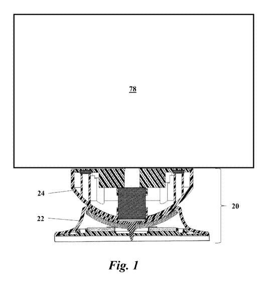
-FIG. 1 is a depiction of an electronic device coupled with a stand according
to
an embodiment of the invention, wherein the stand is depicted in partial cross-
section;
FIG. 2 is a cross-sectional depiction of the base portion of the stand of FIG.
I;
FIG. 3 is an exploded view of the base portion of the stand of FIG.. 1;
FIG. 4 is a cross-sectional view of a docking assembly according to an
embodiment of the invention;
FIG. 5 is an exploded view of the docking assembly of Fla 4;
FIG. 6 is a croSs-sectional View of a docking assembly according to another
embodiment of the invention;
FIG. 7 is an exploded view of the docking assembly of FIG. 6;
FIG. 8. is. a cross-sectional view of the assembled stand of the embodiment of
FIGs..4 and 5 with an electronic device attached;
FIG. 9 is a cross-sectional view of the stand of FIG. 8 in a tilted position;
FIG. 10 is a cross-sectional view of the assembled stand of the embodiment of
FIGs. 6 and 7 with an electronic device attached;
FIG. II is a cross-sectional view of the stand. of FIG. 10 in a tilted
position;
FIG. 12 is a side elevation of a stand according to an embodiment of the
invention attached to an electronic display showing the tilt range (pitch) of
the stand;
FIG: 13 is a front elevation of a stand according to an embodiment of the
invention attached to an electronic display showing the roll range of the
stand;
6
CA 03153249 2022-03-03
WO 2021/045999
PCT/US2020/048815
FIG. 14 is a top plan view of a stand according to an embodiment of the
invention attached to an electronic display showing the rotation (yaw) range
of the:
stand;
FIG. 15 is an isometric view of another embodiment of the invention;
FIG. 16 is a partially exploded front elevation view of the embodiment of FIG
5;
FIG. 17 is an exploded view of the embodiment of FM. 15;
FIG, 18 is an isometric view of another embodiment of the invention;
FIG. 19 is a front elevation view of the embodiment of FIG. 18; and
FIG, 20 is an exploded view of the embodiment of FIG. 18,
While various embodiments are amenable to various modifications and
alternative forms, specifics thereof have been Shown by way of example in the
drawings and will be described in detail. It should be understood, however,
that the
intention is not to limit the claimed inventions to the particular embodiments
described. On the contrary, the intention is to cover all modifications,
equivalents, and
alternatives falling within the spirit and scope of the subject matter as
defined by the
claims.
DETAILED DESCRIPTION OF THE DRAWINGS
In FIGs. I 20 there is depicted stand 20 according to embodiments of the
invention. Stand 20 generally includes base assembly 22 and docking assembly
24. As
depicted in the embodiment of Figs. 2 and 3, base assembly 22 generally
includes
bearing cup .26 made from plastic or non-ferrous metal and defining upwardly
facing
recegs .27 with a smooth upwardly-facing semi-spherical surface 2$ and
opposing
lower surface 29, attractor bowl 30 made from steel or other ferrous metal,
fastener
7
CA 03153249 2022-03-03
WO 2021/045999
PCT/US2020/048815
32, rubber washer 34, metal bearing ring 36, plastic base 38, and rubber disk
40, it
will be appreciated that semi-spherical surface 28 may be any other rounded
shape
such as parabolic. Fastener 32 extends through apertures provided in bearing
cup 26,
attractor bowl 30, rubber washer 34, bearing ring 36, and plastic base 38 to
clamp and
hold the assembly together.
In a first embodiment as depicted in .FIGs. 4 and 5, docking assembly 24
generally includes cup interface 42 presenting smooth semi-spherical outer
surface
44õ securing magnet 46, device interface magnets 48, 50, and device interface
adapter
52. It will be appreciated that outer surface 44 may also be any other rounded
shape
conforming with semi-spherical surface 28 of base assembly 22, such as
parabolic.
Securing magnet 46 is secured. in place with retaining structure 54 extending
from
lower surface 55 of device interface adapter 52 and retaining structure 56
extending
from inner surface 57 of cup interface 42. Device interface magnets 48, 50,
are
supported on bosses 58, 60, extending from cup interface 42, and are received
in
recesses 62, 64, formed in device interface adapter 52. Cup interface 42 and
device
interface adapter 52 can be molded from plastic or formed from any other
suitable
non-magnetic material. Magnets 46, 48, and 50 are preferably high strength
neodymium magnets, but can be filmed from any magnetic material providing
suitable magnetic strength.
In a second embodiment depicted in FIGs. 6 and. 7, docking assembly .24
generally includes cup interface 66 presenting smooth semi-spherical outer
surface
68, securing magnet 70, and device interface adapter 72.. Again, outer
surface. 68 may
also be any other rounded shape conforming with semi-spherical surface 28 of
base
assembly 22, such as parabolic. Cup interface 66 may have stop portion 74
extending
outward from periphery 76 of surface 68. Again, magnet 70 is preferably a
high.
8
CA 03153249 2022-03-03
WO 2021/045999
PCT/US2020/048815
strength neodymium magnet, but can be .fOrmed from any magnetic material
providing suitable magnetic strength.
The embodiment of F1Gs. 4 and 5 is depicted as assembled. and in use in FIG-s.
8 and 9. Base assembly 22 is rested on a planar generally horizontal surface
such as
table 79. Rubber disk 40 provides cushioning and inhibits sliding of base
assembly
22 on surface 81 of table 79. Electronic display .78, such as a tablet or
smartphone, is
received on upper surface 80 of device interface adapter 52. Device interface
magnets
48., 50, attract electronic display 78 to hold it in engagement with device
interface
adapter 5.2. Alternatively, electronic display 78 can be adhered to device
interface
adapter 52 with adhesive, hook and loop material, or attached with mechanical
fasteners or clamps. Cup interface 42 is rested in bearing cup 26 with outer
surface
44 contacting surface 28 to form a ball and Socket type connection. Securing
magnet
46 attracts attractor bowl 30 to hold base assembly 22 and. docking assembly
24 in
engagement. As depicted in FIG. 9, electronic display 78 can be positioned in
roll,
pitch, and yaw by gasping electronic display 78 or cup interface 42 and
sliding cup
interface 42 in bearing cup 26 until the desired position of electronic
display 78 is
reached. Due to the attraction between securing magnet 46 and attractor bowl
30,
electronic display 78 will remain in position until removed or adjusted to a
new
position. While attractor bowl 30 is depicted as a rounded integral structure
abutting
and contbrming to lower surface 29 of bearing cup 26, it will be appreciated
that
attractor bowl 30 could also be formed in alternative shapes such as an
inverted
truncated pyramid, and could be formed from multiple separate ferrous metal
plecOs.,
so long as attractor bowl 30 is disposed in close enough proximity to securing
magnet
46 to provide a magnetic attraction sufficient to hold electronic display 78
in position.
9
CA 03153249 2022-03-03
WO 2021/045999
PCT/US2020/048815
It will be appreciated that electronic display 78 can be detached simply by
lifting electronic display 78 off cup interface 42. Stand 20 according to the,
embodiment of F1Gs 4, 5, 8 and 9, can provide up to +/- 50 degrees p of tilt
range
(pitch), +1- 25 degrees a of roll range, and $60 degrees 0 of rotation (yaw)
for the
mounted electronic display device 78 as depicted in EEGs 12-14.
The embodiment of FICis. 6 and 7 is depicted at.-04ssembled and in use in
FIGs.
1.0 and 11. Electronic display 78, such as a tablet or smartphorte, is
received on. upper
surface 82 of device interface adapter 72 and secured in place with magnets,
adhesive,:
hook and loop material, mechanical fasteners, or clamps. Rubber disk 40
provides
cushioning and inhibits sliding of base assembly 22 on surface 81 of table 79.
Cup
interface 66 is rested in bearing cup 26 with outer surface 69 contacting
surface 28 to
form a ball and socket type connection. Securing magnet 70 attracts attractor
bowl 30
to hold base assembly 22 and docking assembly 24 in engagement. As depicted in
Fig. 11, electronic display 78 can be positioned in roll, pitch, and yaw by
grasping
electronic display 78 or cup interface 66 and sliding cup interface 66 in
bearing cup
26 until the desired position of electronic display 78 is reached. Due to the
attraction
between securing magnet 70 and attractor bowl 30, electronic display 78 will
remain
in position until removed or adjusted to a new position. Again, while
attractor bowl
30 is depicted as a rounded integral structure abutting and conforming to
lower
surface 29 of bearing cup 26, it will be appreciated that attractor bowl 30
could also
be formed. in alternative shapes such as an inverted truncated pyramid, and
could be
formed from multiple separate ferrous metal pieces, so long as attractor bowl
30 is
disposed in close enough proximity to securing magnet 70 to provide a magnetic
attraction sufficient to hold electronic display 78 in position.
CA 03153249 2022-03-03
WO 2021/045999
PCT/US2020/048815
It will be appreciated that electronic display 78 can be detached simply by
removing it from device interface adapter 72. .In the depicted embodiment,
stand 120
offers up to. +/- 25 degrees 1.3 of tilt range (pitch), 41- 25 degrees a of
roll range, and.
360 degrees 0 of rotation (yaw) for the mounted display device 78 as depicted
in FiCis
12-14.
in FICis 15-20, stand 120 is depicted according to additional embodiments of
the invention. Stand 1.20 generally includes base assembly 1.22 and docking
assembly
124. As depicted in a first embodiment in FICis. 15, 16 and 1.7, base assembly
122
generally includes attractor bowl 126 made from steel or other ferrous metal
and
defining upwardly facing recess 128 with a smooth upwardly-facing semi-
spherical
surface 130, fastener 132, washer 134, outer shell 136, base 138, and o-ring.
140. It
will be appreciated that semi-spherical surface 130 may be any other rounded
shape
such as parabolic. Fastener 132 extends through apertures provided in
attractor bowl
1.26, washer 134, and base 138 to clamp and hold the assembly together.
in the embodiment of FIGs. 15, 16, and 17 docking assembly 1.24 generally
includes cup interface 142 presenting smooth semi-spherical outer surface 144,
securing magnet 146, device interface magnets 148, 150, device interface
adapter 152,
and magnet retainer 154. it will be appreciated that outer surface 1.11 may
also he any
other rounded shape conforming with semi-spherical surface 130 of base
assembly
122, such as parabolic. Securing magnet 146 is secured in place in central
recess 156
of cup interface 142 with adhesive disk 158. Device interface magnets 148,
150, are
received in recesses 160, 162, defined in magnet retainer 154. Cup interface
142 and
device interface adapter 152 can be molded from plastic or formed from any
other
suitable non-magnetic material. Magnets 146, 148, and 150 are preferably high
11
CA 03153249 2022-03-03
WO 2021/045999
PCT/US2020/048815
strength neodymium magnets, but can be formed from any magnetic material
providing suitable magnetic strength.
In a second embodiment depicted in FIGs. 18, 19 and 20õ base assembly 122
generally includes attractor bowl 126 made from steel or other ferrous metal_
and
defining upwardly facing recess 128 with a smooth upwardly-facing semi-
spherical
surface 130, fastener 132 washer -134, outer shell 1 36, base 138, and 0-ring
140. It
will be appreciated that semi-spherical. surface 130 may be any other rounded
shape
such as parabolic. Fastener 132 extends through apertures provided in
attractor bowl
126, washer 134, and base 138 to clamp and hold the assembly together,
In the embodiment of F1Gs, 18, 19, and 20 docking assembly 124 generally
includes cup interface .142 presenting smooth semi-spherical outer surface
144,
securing magnet 146, device interface magnets 148, 150, device interface
adapter 152,
and magnet retainer 154, 'It will be appreciated that outer surface 144 may
also be any
other rounded shape conforming with semi-spherical surface 130 of base
assembly
122, such as parabolic. Securing magnet 146 is secured in place in central
recess 156
of cup interface 1.42 with adhesive disk 158. Device interface magnets 148,
1.50, are
received in recesses 160, 162, defined in magnet retainer 154. Cup interface
142 and
device interface adapter 152 can be molded from plastic or formed from any
other
suitable non-magnetic material. Magnets 146, 148, and 150 are preferably high
strength neodymium magnets, but can be formed from any magnetic material
providing suitable magnetic strength.
The embodiments of FlGs. 15-20 are depicted as assembled in 1,1{1s. 15 and
18. Base. assembly 122 is -rested on a planar generally horizontal surface
such as a.
table or desk 79. An electronic display (not depicted), such as a tablet or
smartphoneõ
is received on upper surface 180 of device interface adapter 152. Device
interface
12
CA 03153249 2022-03-03
WO 2021/045999
PCT/US2020/048815
magnets 148, 150, attract the electronic display to hold it in engagement with
device
interface adapter 152. Alternatively, the electronic display can be adhered to
device
interface adapter 152 with adhesive, hook and loop material, or attached with
mechanical fasteners or clamps. Cup interface 142 is rested in attractor bowl
126 to
form a ball and socket type connection. Securing magnet 146 attracts attractor
bowl
126 to hold base assembly 122 and docking assembly .124 in engagement. The
electronic display can be positioned in roll, pitch, and yaw by grasping the
electronic
display or cup interface 142 and sliding cup interface 14.2 in attractor bowl
.126 until
the desired position of the electronic display is reached. Due to the
attraction between
securing magnet 146 and attractor bowl 126, the electronic display will remain
in
position until removed of adjusted to a new position.
It will be appreciated that the electronic display can be detached simply by
lifting it off cup interface 14.2. Again, stand 120 according to the
embodiments of
FIGs 15-20, can provide up to +1- 50 degrees p of tilt range (pitch), +1,-; 25
degrees a
of roll range, and 360 degrees 0 of rotation (yaw) for the mounted electronic
display
device as depicted in FIGs 12-14.
Various embodiments of systems, devices, and .methods have been described
herein. These embodiments are given .only by way of example and are not
intended to
limit the scope of the claimed inventions, It should be appreciated, moreover,
that the
various features of the embodiments that have been described may be combined
in
various ways to produce numerous additional embodiments, Moreover, while
various
materials, dimensions, shapes, configurations and locations, etc. have been
described
for use with disclosed embodiments, others besides those disclosed may he
utilized
without exceeding the scope of the claimed inventions.
13
CA 03153249 2022-03-03
WO 2021/045999
PCT/US2020/048815
Persons of ordinary skill in the relevant arts will recognize that the subject
matter hereof may comprise fewer features than illustrated in any individual
embodiment described above. The embodiments described herein are not meant to
be
an exhaustive presentation of the Ways in Which the various features of the
subject
matter hereof may be combined. Accordingly, the embodiments are not mutually
exclusive combinations of features; rather, the various embodiments can
comprise a
COM bination of different individual features selected from: different
individual.
embodiments, as understood by persons of ordinary skill in the art. Moreover,
elements described with respect to one embodiment can: be implemented in other
embodiments even when not described in such embodiments unless otherwise
noted.
Although a dependent claim may refer in the claims to a specific combination
with one or more other claims, other embodiments can also include a
combination of
the dependent claim with the subject matter of each other dependent claim or a
combination of one or more features with other dependent or independent
claims,
Such combinations are proposed herein unless it is stated that a specific
combination
is not intended.
Any incorporation by reference of documents above is limited such that no
subject matter is incorporated that is contrary to the explicit disclosure
herein. Any
incorporation by reference of docuine.nts above is further limited such that
no claims
included in the documents are incorporated by .reference herein, Any
incorporation by
reference of documents above is yet further limited such that any definitions
provided
in the documents are not incorporated by reference herein unless. expressly
included
herein.
For purposes of interpreting the claims, if is expressly intended that the
14
CA 03153249 2022-03-03
WO 2021/045999
PCT/US2020/048815
provisions of 35 USE, 112(t) are not to be invoked unless the specific terms
"means for" or "step for" are recited in a claim.