Note: Descriptions are shown in the official language in which they were submitted.
WO 2021/067592
PCT/US2020/053791
METHOD AND APPARATUS FOR DELIVERING DRUGS TO THE SPINE
OF A PATIENT, AND/OR FOR DELIVERING OTHER MATERIALS
AND/OR DEVICES TO THE SPINE OF A PATIENT
10
Reference To Pending Prior Patent Applications
This patent application:
(1) is a continuation-in-part of pending prior U.S. Non-Provisional Patent
Application Serial No. 16/380,777, filed 04/10/2019 by Pain Away Solutions,
LLC and Gabriel Garcia Diaz for LUMBAR SYRINGE GUIDE ASSEMBLY
(Attorney's Docket No. PAIN-1), which patent application claims benefit of
(A) prior U.S. Provisional Patent Application Serial No.
62/655,666, filed 04/10/2018 by Gabriel Garcia Diaz for LUMBAR SYRINGE
GUIDE ASSEMBLY (Attorney's Docket No. GARCIA-DIAZ.G-LZ.001PP); and
(2) claims benefit of pending prior U.S. Provisional Patent Application
Serial No. 62/908,717, filed 10/01/2019 by Pain Away Solutions, LLC and
Gabriel Garcia Diaz et al. for METHOD AND APPARATUS FOR
DELIVERING DRUGS TO THE SPINE OF A PATIENT, AND/OR FOR
DELIVERING OTHER MATERIALS AND/OR DEVICES TO THE SPINE OF
A PATIENT (Attorney's Docket No. PAIN-02030405 PROV).
CA 03153355 2022-3-31
WO 2021/067592
PCT/U52020/053791
- 2 -
The three (3) above-identified patent applications are hereby incorporated
herein by reference.
Field Of The Invention
This invention relates to drug delivery systems in general, and more
particularly to drug delivery systems for delivering drugs to the spine of a
patient.
This invention also relates to delivering other materials and/or devices to
the spine
of a patient. Among other things, the present invention comprises a system of
different components which are intended to be used collectively for the
purpose of
3.0 delivering drugs to the spine of a patient. However, it should
also be appreciated
that the different components (i.e., devices) of the system may be used
independently of one another, or may be used with other devices, or may be
used
for other purposes, etc., such as utilizing the spring-loaded syringe assist
device
(see below) for assisting in the delivery of intravenous medications to
patients.
Also, the needle guide (see below) may be used for pedicle screw placement,
with
or without the use of navigation software, etc.
Background Of The Invention
Physicians frequently need to inject drugs into the spine of a patient, e.g.,
to
treat patients with chronic back pain. In many caves the spinal injection must
be fluoroscope-
guided to ensure that the drugs are placed into the correct locations in the
patients'
anatomy. In many cases, an individual patient may need to have injections in
multiple locations within the spine.
Currently, physicians handle one needle at a time, which means that they
need to find the correct location for each needle placement prior to insertion
of the
medication of the syringe into the patient. The need to handle each needle
independently leaves room for error, particularly when it comes to the
precision
of the insertion of the needle into a patient's anatomy. Moreover, because
each
CA 03153355 2022-3-31
WO 2021/067592
PCT/U52020/053791
- 3 -
needle has to be handled separately, this adds time to the procedure
and, in some cases, additional radiation exposure to the patient and the
healthcare
staff involved in the care of the patient.
Therefore, there is a need for a novel drug delivery system which assists
a physician in inserting and holding in place multiple needles, while ensuring
the accuracy of the insertion angles and locations of the multiple needles,
and
delivers medication through the multiple needles to a patient.
Summary Of The Invention
3.0 The present invention relates to a method and apparatus
for delivering
drugs to the spine of a patient.
More particularly, the present invention comprises the provision and use
of a novel drug delivery system which comprises a plurality of needles; a
needle
guide for guiding and holding the plurality of needles during insertion into
the
patient's spine; a syringe containing the drug which is to be delivered into
the
patient's spine; a port multiplier comprising an inlet port and a plurality of
outlet
ports; and a plurality of tubes for providing a connection between the outlet
ports
of the port multiplier and the plurality of needles.
In use, the needle guide is positioned against the skin of the patient
adjacent to the spine; the needle guide is used to guide the plurality of
needles as
they are inserted into the spine and to hold them in position; the port
multiplier is
connected to the syringe containing the drug which is to be delivered; tubes
are
used to connect the outlet ports of the port multiplier to the needles; and
the
syringe is used to eject the drug into the port multiplier, through the tubes
and
through the needles so as to be injected into the desired locations in the
spine of
the patient.
The present invention may also be used for delivering other materials
(e.g., non-drug fluids including biologics, etc.) and/or devices (e.g.,
pedicle
CA 03153355 2022-3-31
WO 2021/067592
PCT/U52020/053791
- 4 -
screws, bone implants, etc.) to the spine of a patient.
In one form of the invention, there is provided a drug delivery system
comprising:
a plurality of needles;
a needle guide for guiding and holding the plurality of needles during
insertion into a patient's spine;
a syringe containing a drug which is to be delivered into the patient's
spine;
a port multiplier comprising an inlet port connectable to the syringe and a
3.0 plurality of outlet ports; and
a plurality of tubes for providing fluid connections between the outlet
ports of the port multiplier and the plurality of needles.
In another form of the invention, there is provided a method for delivering
drugs, the method comprising:
providing a drug delivery system comprising:
a plurality of needles;
a needle guide for guiding and holding the plurality of needles
during insertion into a patient's spine;
a syringe containing a drug which is to be delivered into the
patient's spine;
a port multiplier comprising an inlet port connectable to the
syringe and a plurality of outlet ports; and
a plurality of tubes for providing fluid connections between the
outlet ports of the port multiplier and the plurality of needles;
positioning the needle guide against the skin of the patient adjacent to the
spine;
using the needle guide to guide the plurality of needles as they are inserted
into the spine and hold them in position;
CA 03153355 2022-3-31
WO 2021/067592
PCT/U52020/053791
- 5 -
connecting the port multiplier to the syringe containing the drug which is
to be delivered;
connecting the tubes to the outlet ports of the port multiplier and to the
needles; and
using the syringe to eject the drug into the port multiplier, through the
tubes and through the needles so as to be injected into the desired locations
in the
spine of the patient.
In another form of the invention, there is provided a delivery system for
delivering a plurality of cannulated devices into the anatomy of a patient,
the
delivery system comprising:
a plurality of guidewires;
a frame; and
a plurality of guidewire supports selectively movably mounted to the
frame, wherein each of the guidewire supports is configured to guide and hold
a
guidewire during insertion into the anatomy of a patient;
wherein the frame comprises two frame supports connected to one another
by at least one adjustable arm;
wherein each of the frame supports comprises a frame lumen and a pair of
slots communicating with the frame lumen;
wherein each of the guidewire supports comprises:
a body slidably disposed in a frame lumen of a frame support; and
a member configured to slidably support a guidewire and to
selectively lock the body in a selected position within a frame lumen of a
frame
support.
In another form of the invention, there is provided a method for delivering
a plurality of cannulated devices into the anatomy of a patient, the method
comprising:
providing a delivery system comprising:
CA 03153355 2022-3-31
WO 2021/067592
PCT/U52020/053791
- 6 -
a plurality of guidewires;
a frame; and
a plurality of guidewire supports selectively movably mounted to
the frame, wherein each of the guidewire supports is configured to guide and
hold
a guidewire during insertion into the anatomy of a patient;
wherein the frame comprises two frame supports connected to one
another by at least one adjustable arm;
wherein each of the frame supports comprises a frame lumen and a
pair of slots communicating with the frame lumen;
wherein each of the guidewire supports comprises:
a body slidably disposed in a frame lumen of a frame
support; and
a member configured to slidably support a guidewire and to
selectively lock the body in a selected position within a frame lumen of a
frame
support;
positioning the frame against the anatomy of the patient;
using the plurality of guidewire supports to guide the plurality of
guidewires as they are inserted into the anatomy of the patient;
withdrawing the frame and the plurality of guidewire supports while
leaving the plurality of guidewires inserted into the anatomy of the patient;
and
delivering a plurality of cannulated devices into the anatomy of a patient
by passing the cannulated devices over the plurality of guidewires.
In another form of the invention, there is provided a guide for guiding and
holding a plurality of objects during insertion into a patient's body, the
guide
comprising:
a frame; and
a plurality of object supports selectively movably mounted to the frame,
wherein each of the object supports is configured to guide and hold an object
CA 03153355 2022-3-31
WO 2021/067592
PCT/U52020/053791
- 7 -
during insertion into the patient's body;
and further wherein each of the object supports is reconfigurable between:
(i) a first configuration wherein the object support is movable at
least one of (a) axially along the frame and (b) rotatably relative to the
frame; and
(ii) a second configuration wherein the object support is fixed
relative to the frame.
In another form of the invention, there is provided a syringe assist device
for use with a syringe, wherein the syringe comprises (a) a syringe body
having a
cavity and an output port, and (b) a plunger movably disposed in the cavity
for
driving the contents of the cavity out of the output port, the syringe assist
device
comprising:
a housing for mounting to the syringe body;
a driver for engaging the plunger and moving the plunger so as to drive the
contents of the cavity out of the output port; and
a power unit for moving the driver.
In another form of the invention, there is provided a port multiplier
comprising:
a hollow body having an interior;
an input port in fluid communication with the interior of the hollow body,
the input port being configured for attachment to a syringe; and
a plurality of output ports in fluid communication with the interior of the
hollow body, each of the plurality of output ports being configured for
attachment
to a fluid line.
Brief Description Of The Figures
These and other objects and features of the present invention will be more
fully disclosed or rendered obvious by the following detailed description of
the
preferred embodiments of the invention, which is to be considered together
with
CA 03153355 2022-3-31
WO 2021/067592
PCT/US2020/053791
- 8 -
the accompanying drawings wherein like numbers refer to like parts, and
further
wherein:
Figs. 1-8, 8A, 9, 10, 10A and 11-19 are schematic views showing one
preferred form of the present invention;
Figs. 20 and 20A-20J are schematic views showing an alternative form of
the needle guide;
Fig. 21 is a schematic view showing a spring-loaded syringe assist device
which may be used with the syringe of the system of the present invention
(and/or
may be used as an independent syringe assist device for medication delivery to
patients);
Fig. 21A is a schematic view showing an alternative form of the spring-
loaded syringe assist device of Fig. 21; and
Fig. 22 is a schematic view showing a vial adapter which may be used with
the system of the present invention.
Detailed Description Of The Preferred Embodiments
In one form of the invention, the present invention comprises the provision
and use of a novel drug delivery system 5 for delivering a drug to the spine
of a
patient.
Drug Delivery System 5 In General
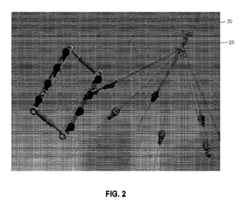
In one form of the invention, and looking now at Figs. 1-8, 8A, 9, 10, 10A
and 11-19, drug delivery system 5 comprises a plurality of needles 10; a
needle
guide 15 for guiding and holding the plurality of needles during insertion
into the
patient's spine; a syringe 20 containing the drug which is to be delivered to
the
spine of the patient; a port multiplier 25 comprising an inlet port (see
below) and
a plurality of outlet ports (see below); and a plurality of tubes 30 for
providing a
connection between the outlet ports of the port multiplier and the plurality
of
CA 03153355 2022-3-31
WO 2021/067592
PCT/U52020/053791
- 9 -
needles.
The Plurality Of Needles 10
Each of the plurality of needles 10 comprises a shaft 35 having a sharp
distal tip 40 and a hub 45. See Fig. 3. A lumen 50 extends between sharp
distal
tip 40 and hub 45. Hub 45 is configured for connection to a tube 30, e.g., it
may
comprise a luer lock connector or another connector of the sort used to
connect
fluid lines. Shaft 35 may be straight or bent as appropriate.
3.0 Needle Guide 15
Needle guide 15 generally comprises a frame 55. Frame 55 preferably
comprises two parallel supports 60, which are connected to one another by at
least
one adjustable arm 65. See Fig. 8. Each parallel support 60 is hollow (i.e.,
it
comprises an interior lumen 68, see Fig. 8A) and comprises a distal surface 70
facing the patient and a proximal surface 75 facing the surgeon. One or more
slots 80 are formed in each parallel support 60. Slots 80 open on distal
surface 70
and proximal surface 75 and intersect interior lumens 68. The at least one
adjustable arm 65 preferably telescopes so as to allow the distance between
the
two parallel supports 60 to be adjusted. Parallel supports 60 and the at least
one
adjustable arm 65 are preferably radiolucent, with radiopaque markers 85. By
way of example but not limitation, parallel supports 60 and the at least one
adjustable arm 65 may be formed out of plastic, and radiopaque markers 85 may
comprise a metal coating disposed on parallel supports 60.
A plurality of needle supports 90 (Fig. 8A) are adjustably mounted to
interior lumens 68 and slots 80 of parallel supports 60. More particularly,
each of
the needle supports 90 comprises a spherical body 95 slidably disposed in
interior
lumens 68 of parallel supports 60. Spherical bodies 95 are sized to be
slightly
smaller than interior lumens 68 of parallel supports 60 so that spherical
bodies 95
CA 03153355 2022-3-31
WO 2021/067592
PCT/US2020/053791
- 10 -
can slide along interior lumens 68. At the same time, spherical bodies 95 are
sized to be slightly larger than the width of slots 80 such that spherical
bodies 95
cannot pass out of slots 80. Each spherical body 95 comprises a threaded bore
100. Each of the needle supports 90 also comprises a body 105 having a
threaded
projection 110 at its distal end. Threaded projection 110 is sized to extend
through slots 80 of parallel supports 60 and make a threaded engagement with
threaded bore 100 of spherical body 95. Threaded projection 110 is narrower
than
slots 80 so that when threaded projection 110 is received by threaded bore 100
of
spherical body 95, and body 105 is spaced from proximal surface 75 of parallel
support 60, threaded projection 110 can pivot (on rotating spherical body 95)
relative to parallel support 60. Body 105 and threaded projection 110 comprise
a
lumen 115 extending therethrough. Lumen 115 is sized to slidably receive the
shaft 35 of a needle 10 so as to guide and support shaft 35 of a needle 10.
Note
that in an alternative approach for guided delivery, needle supports 90 may be
replaced with alternative targeted supports for the guided delivery of
devices, e.g.,
such as the guided delivery of pedicle screws, and/or guidewires for
delivering
pedicle screws, which may or may not be used with navigation software.
On account of the foregoing construction, when threaded projection 110 is
received by threaded bore 100 of spherical body 95, body 105 can be (i) spaced
from proximal surface 75 of parallel support 60, whereby to allow needle
support
90 to move longitudinally along slot 80 and to pivot relative to the
longitudinal
axis of parallel support 60, whereby to adjust the location and orientation of
lumen 115 of a needle support 90, and (ii) brought into engagement with
proximal
surface 75 of parallel support 60, whereby to lock needle support 90 in
position in
slot 80 so as to prevent longitudinal movement of needle support 90 and to
prevent pivotal movement of needle support 90 relative to the longitudinal
axis of
parallel support 60, whereby to fix the location and orientation of lumen 115
of a
needle support 90.
CA 03153355 2022-3-31
WO 2021/067592
PCT/U52020/053791
- 11 -
In one preferred form of the invention, parallel supports 60 are preferably
formed out of two halves 60A, 60B which may be joined together during
manufacture, such that spherical bodies 95 of needle supports 90 may be loaded
into interior lumens 68 of parallel supports 60 before halves 60A, 60B are
joined
together.
If desired, needle supports 90 may be formed out of radiolucent materials
and, if desired, a radiopaque marker may be disposed on a portion of needle
supports 90 to assist in targeting needle supports 90 (e.g., a radiopaque
marker
may be disposed on the distal end of threaded projection 110).
3.0
Syringe 20
Syringe 20 may comprise a standard syringe, e.g., a hollow body 120
having an outlet port 125 and a plunger 130 slidably received in hollow body
120.
See Fig. 11. The drug to be delivered to the spine is disposed within hollow
body
120, such that distal movement of plunger 130 causes the drug to be ejected
out of
outlet port 125.
Port Multiplier 25
Port multiplier 25 preferably comprises a hollow body 135 having a single
inlet port 140 and a plurality of outlet ports 145, such that a fluid injected
into
inlet port 140 will be directed out the plurality of outlet ports 145. See
Fig. 16.
Caps 150 may be provided for selectively closing off individual ones of outlet
ports 145. Alternatively and/or additionally, valves 152 may be provided in
outlet
ports 145 for selectively dosing off individual ones of outlet ports 145.
The Plurality Of Tubes 30
Each of the plurality of tubes 30 comprises a flexible hollow tubular body
155 having a needle connector 160 at one end for connecting with hub 45 of
CA 03153355 2022-3-31
WO 2021/067592
PCT/U52020/053791
- 12 -
needle 10 (see Fig. 19), and a port multiplier connector 165 at the other end
for
connecting to an outlet port 145 of port multiplier 25 (see Fig. 12).
Needles 10 Being Pre-Fixed To Tubes 30 And/Or Tubes 30 Being Pre-
Fixed To Port Multiplier 25
Note that, if desired, needles 10 may be pre-fixed to tubes 30, and/or tubes
30 may be pre-fixed to outlet ports 145 of port multiplier 25.
Use Of Drug Delivery System 5
In use, needle guide 15 is positioned against the skin of the patient
adjacent to the spine; needle guide 15 is adjusted so that it can guide the
plurality
of needles 10 as they are inserted into the spine and hold them in position;
port
multiplier 25 is connected to syringe 20 containing the drug which is to be
delivered; tubes 30 are used to connect the outlet ports 145 of port
multiplier 25 to
the needles 10; and the syringe 20 is used to eject the drug into port
multiplier 25,
through tubes 30 and through needles 10 so as to be injected into the desired
locations in the spine of the patient.
More particularly, in one preferred form of the invention, drug delivery
system 5 may be used as follows.
First, needle guide 15 is positioned against the skin of the patient adjacent
to the spine. Adjustable arm 65 is adjusted as necessary so as to position the
two
parallel supports 60 on either side of the patient's spine. If necessary,
frame 55
may be secured to the patient, e.g., with tape, a Velcro strap, etc.
Next, needle guide 15 is used to guide a plurality of needles 10 as they are
inserted into the spine and to hold the needles in position. This may be done
by
loosening a body 105 of a needle support 90 relative to the corresponding
spherical body 95 of that needle support 90, sliding the needle support 90
along a
slot 80 and adjusting its angular position as necessary, and then advancing a
CA 03153355 2022-3-31
WO 2021/067592
PCT/U52020/053791
- 13 -
needle 10 through lumen 115 of the needle support 90 so as to advance the
needle
to the desired location. Preferably this is done using fluoroscopic guidance
(e.g., with a needle support in its "loosened" condition, a needle is advanced
through the needle support and its position checked using fluoroscopy; if
5 necessary, the needle may be withdrawn and repositioned, until the
needle is in its
proper position). When needle 10 is properly positioned in the spine, body 105
may be screwed down so as to securely engage parallel support 60, whereby to
lock needle support 90 from longitudinal and pivotal motion, thereby keeping
needle 10 in proper position The foregoing process is then repeated for
3.0 additional needle supports 90 and needles 10 until an appropriate
number of
needles 10 are properly positioned.
Then inlet port 140 of port multiplier 25 is connected to outlet port 125 of
syringe 20 which contains the drug which is to be delivered.
Tubes 30 are then connected to outlet ports 145 of port multiplier 25 and
to hubs 45 of needles 10.
Then syringe 20 is used to flow the drug into port multiplier 25, through
tubes 30 and through needles 10 so as to be injected into the desired
locations in
the spine.
Alternative Needle Guide
If desired, needle supports 90 may comprise an alternative construction.
More particularly, in this form of the invention, and looking now at Figs. 20
and
20A-20J, needle supports 90A may be provided. Needle supports 90A generally
comprise a tubular body 95A for slidable positioning within lumens 68 of
parallel
supports 60. Tubular body 95A comprises diametrically-opposed openings 100A.
Needle supports 90A also comprise a tapered body 105A for selected disposition
in openings 100A of tubular body 95A. Tapered body 105A comprises a lumen
115A.
CA 03153355 2022-3-31
WO 2021/067592
PCT/U52020/053791
- 14 -
In this form of the invention, when needle supports 90A are to be movably
disposed in lumens 68, tapered body 105A is lightly positioned in openings
100A
so as to cause nominal expansion of tubular body 95A. When needle supports
90A are to be locked in position in lumens 68 of parallel supports 60, tapered
body 105A is forced distally, whereby to dilate openings 100A and thereby
enlarge tubular body 95A, whereby to lock tubular body 95A within lumens 68 of
parallel supports 60. Note that tubular bodies 95A extend through slots 80 in
parallel supports 60, and needles 10 extend through lumens 115A of tapered
bodies 105A
3.0 If desired, needle supports 90A may be formed out of
radiolucent
materials and, if desired, a radiopaque marker may be disposed on a portion of
needle supports 90A to assist in targeting needle supports 90A (e.g., a
radiopaque
marker may be disposed on the distal end of tapered body 105A).
Spring-Loaded Syringe Assist Device
In another form of the invention, and looking now at Fig. 21, a spring-
loaded syringe assist device 170 may be provided to power distal movement of
plunger 130 of syringe 20. More particularly, in this form of the invention,
spring-loaded syringe assist device 170 comprises an assist plunger 175 which
engages plunger 130 of syringe. Assist plunger 175 is powered by a spring 180.
An actuator safety lock 185 is provided to prevent assist plunger 175 from
moving under the influence of spring 180 until actuator safety lock 185 is
removed.
In this form of the invention, in use, spring-loaded syringe assist device
170 is mounted to the proximal end of syringe 20 so that assist plunger 175
engages plunger 130 of syringe 20, and then, when the drug is to be deployed,
actuator safety lock 185 is removed, whereupon spring 180 causes assist
plunger
175 of spring-loaded syringe assist device 170 to drive plunger 130 of syringe
20
CA 03153355 2022-3-31
WO 2021/067592
PCT/U52020/053791
- 15 -
distally, whereby to dispense the drug in syringe 20.
If desired, and looking now at Fig. 21A, spring-loaded syringe assist
device 170 may be provided with a brake lever 186 for increased control of
dispensing the drug in syringe 20.
More particularly, brake lever 186 comprises a spring arm 187 which
normally holds a finger 188 in engagement with teeth 175A on assist plunger
175
of spring-loaded syringe assist device 170, whereby to lock assist plunger 175
against axial movement. Squeezing spring arm 187 (e.g., between the thumb and
forefinger of a user) withdraws finger 188 from engagement with teeth 175A on
3.0 assist plunger 175, whereby to enable assist plunger 175 to move
axially under the
power of the aforementioned spring 180.
In use, spring-loaded syringe assist device 170 is mounted to syringe 20
by positioning the finger grips of the syringe in slots 189 at the base of
spring-
loaded syringe assist device 170 with plunger 130 of syringe 20 being disposed
within the body of spring-loaded syringe assist device 170, adjacent to the
distal
end of assist plunger 175. When the drug is to be dispensed from syringe 20,
spring arm 188 is squeezed so as to withdraw finger 188 from engagement with
teeth 175A of assist plunger 175, whereby to "unlock" assist plunger 175 of
spring-loaded syringe assist device 170 so that assist plunger 175 can move
distally under the power of spring 180, whereby to dispense the drug in
syringe
20. When the desired amount of the drug has been dispensed, spring arm 187 is
released so as to cause finger 188 to re-engage teeth 175A of assist plunger
175,
whereby to "lock" assist plunger 175 of spring-loaded syringe assist device
170
from further distal movement under the power of spring 180. If and when
additional drug is to be dispensed from syringe 20, spring arm 188 is squeezed
again so as to withdraw finger 188 from engagement with teeth 175A of assist
plunger 175, whereby to "unlock" assist plunger 175 of spring-loaded syringe
assist device 170 so that assist plunger 175 can move distally under the power
of
CA 03153355 2022-3-31
WO 2021/067592
PCT/U52020/053791
- 16 -
spring 180, whereby to dispense the drug in syringe 20. When an appropriate
amount of the drug has been dispensed, spring arm 187 is released so as to
"lock"
assist plunger 175 against further movement.
It should also be appreciated that, if desired, the spring 180 of spring-
loaded syringe assist device 170 may be replaced by a powered mechanism, e.g.,
an electrical motor.
Filling Syringe 20
In many cases, syringe 20 may be pre-filled with the drug which is to be
injected into the spine. However, if desired, syringe 20 may be filled at the
time
of use. In this case, and looking now at Fig. 22, it can be desirable to
interpose a
vial adapter 190 between the outlet port 125 of syringe 20 and inlet port 140
of
port multiplier 25. Vial adapter 190 preferably comprises a T-shaped hollow
body 195 having a first port 200 connectable to the outlet port 125 of syringe
20,
a second port 205 connectable to the inlet port 140 of port multiplier 25, and
a
needle line 210 connectable to a vial 215. A check valve 220 is provided in T-
shaped hollow body 195 at second port 205, and a check valve 225 is provided
in
T-shaped hollow body 195 at needle line 210. Check valve 220 allows fluid to
flow from T-shaped hollow body 195 to port multiplier 25 but prevents fluid
from
flowing from port multiplier 25 into T-shaped hollow body 195. Check valve 225
allows fluid to flow from needle line 210 into T-shaped hollow body 195 but
prevents fluid from flowing from T-shaped hollow body 195 into needle line
210.
When syringe 20 is to be loaded from vial 215, plunger 130 is drawn
proximally so as to create suction at outlet port 125 of syringe 20. Check
valve
225 allows the drug in vial 215 to be drawn into syringe 20, with check valve
220
preventing air from passing out of port multiplier 25 and into syringe 20.
When
the drug is to be dispensed from syringe 20, plunger 130 is moved distally.
When
this occurs, check valve 220 prevents the drug exiting outlet port 125 of
syringe
CA 03153355 2022-3-31
WO 2021/067592
PCT/U52020/053791
-17-
20 from re-entering needle line 210, and check valve 225 allows the drug to
pass
into port multiplier 25.
Use Of The System To Deliver Other Materials
In the foregoing disclosure, the system of the present invention is
discussed in the context of delivering drugs (e.g., analgesics) to the spine
of the
patient. However, it should be appreciated that the present invention may also
be
used for delivering other materials (e.g., non-drug fluids including
biologics, etc.)
to the spine of a patient.
Use Of Needle Guide 15 For Deploying Other Objects Into The Body Of
A Patient
It should be appreciated that the present invention may also be used in
medical procedures which require targeted deployment of objects into the spine
or
other anatomy of a patient.
By way of example but not limitation, needle guide 15 may be used to
deploy pedicle screws into the spine of a patient. More particularly, in this
form
of the invention, needle guide 15 may be used, with fluoroscopic imaging, or
navigation software, to set a plurality of guidewires into the pedicles of the
spine.
Once one or more guidewires have been targeted into the pedicles of the spine
using needle guide 15, the needle guide may be removed and then pedicle screws
may be moved down the guidewires and advanced into the pedicles of the spine.
By way of further example but not limitation, needle guide 15 may be
used to deploy bone implants into the spine of a patient.
By way of still further example but not limitation, needle guide 15 may be
used to deploy radiofrequency (RF) ablation probes into the spine of a patient
for
the targeted ablation of tissue.
And by way of further example but not limitation, needle guide 15 can be
CA 03153355 2022-3-31
WO 2021/067592
PCT/U52020/053791
- 18 -
used to deploy sensory nerve stimulator (SNS) leads into the spine of a
patient for
the targeted application of pain-relieving electrical stimulation.
It will be appreciated by those skilled in the art that the present invention
may also be used in many other situations which require targeted deployment of
objects into the anatomy of a patient.
Needle Supports 90 With Reduced Degrees Of Freedom
In the foregoing sections, needle supports 90 are disclosed as being, in
their unlocked configuration, axially movable along parallel supports 60 and
rotationally movable about the longitudinal axes of parallel supports 60.
However, it should be appreciated that, if desired, needle supports 90 may be
provided with reduced degrees of freedom.
By way of example but not limitation, needle supports 90 may be
configured so that, in their unlocked configuration, needle supports 90 are
axially
movable along parallel supports 60 but not rotationally movable about the
longitudinal axes of parallel supports 60.
By way of further example but not limitation, needle supports 90 may be
configured so that, in their unlocked configuration, needle supports 90 are
rotationally movable about the longitudinal axes of parallel supports 60 but
not
axially movable along parallel supports 60.
By way of still farther example but not limitation, needle supports 90 may
be axially and rotationally fixed relative to parallel supports 60.
It should be further appreciated that various means may be used to mount
needle supports 90 to parallel supports 60, e.g., screw mounts, clamp mounts,
press fit mounts, glide fit mounts, magnetic mounts, etc.
Use Of The System In The Veterinary Space
While the primary application for the novel delivery system of the present
CA 03153355 2022-3-31
WO 2021/067592
PCT/US2020/053791
- 19 -
invention is intended to be for human use, it should also be appreciated that
the
novel delivery system may also be used in veterinary applications.
Modifications Of The Preferred Embodiments
It should be understood that many additional changes in the details,
materials, steps and arrangements of parts, which have been herein described
and
illustrated in order to explain the nature of the present invention, may be
made by
those skilled in the art while still remaining within the principles and scope
of the
invention.
3.0
CA 03153355 2022-3-31