Note: Descriptions are shown in the official language in which they were submitted.
CA 03153536 2022-03-04
WO 2021/(1465.15
PCT/US2020/049765
AUTONOMOUS BAGGAGE DEVICE
CROSS-REFERENCE TO RELATED APPLICATION
[0m] The present application claims priority to U.S. Provisional Application
Serial Number 62/896,482, filed September 5, 2019, 2019 and United States
Non-Provisional Patent Application Serial No. 17/014,903, filed September 8,
2020, whereby each of the above-listed patent applications is incorporated
herein by reference in their entirety.
TECHNICAL FIELD
[0002] The present invention relates to the field of baggage and cargo
handling
for the airline industry, and more particularly, to a device for automated
baggage handling.
BACKGROUND
[0003] A passenger checks into an airport terminal with baggage. The terminal
takes the passenger's baggage and registers the baggage with a baggage
number. The baggage number may be an International Air Transport
Association (IATA) baggage identifier with a ten-digit number, the ten-digit
number including a leading digit, a three-digit airline code, and a six-digit
bag
number. The baggage may then be directed to a baggage handling area. The
baggage may then be loaded from the baggage handling area onto an airplane
by a baggage cart, a baggage tug, and a belt loader. Similarly, the airplane
may
be unloaded with the baggage cart, the baggage tug, and the belt loader. The
baggage cart may require a baggage handler to load and unload baggage. The
baggage cart may be loaded and unload from the baggage cart by the belt
loader. The belt loader must be placed to receive baggage from the baggage
handling area and output the baggage to the baggage cart. The belt loader and
CA 03153536 2022-03-04
WO 2021/(146545
PCT/US2020/049765
the baggage cart must be manually moved between the various airport
locations. The belt loader and baggage cart may also provide limited sorting
functionality to storage areas on the baggage cart, if any storage areas are
even
present. This may reduce the airlines knowledge of where a baggage is
currently stored.
[0004] Therefore, it would be advantageous to provide a device that cures the
shortcomings described above.
SUMMARY
[0005] A device is disclosed in accordance with one or more illustrative
embodiments of the present disclosure. In one illustrative embodiment, the
device includes a storage portion. In another illustrative embodiment, the
storage portion includes a first storage area, a second storage area, and a
third
storage area. In another illustrative embodiment, the first storage area is
vertically adjacent to the second storage area and horizontally adjacent to
the
third storage area. In another illustrative embodiment, the first storage
area, the
second storage area, and the third storage area are configured to receive
luggage. In another illustrative embodiment, the device includes an exterior
conveyor having a first and a second end. In another illustrative embodiment,
the exterior conveyor is configured to convey the baggage from the first end
to
the second end. In another illustrative embodiment, the device includes a
lateral
sorter configured to laterally sort the baggage between a number of lateral
storage areas. In another illustrative embodiment, the device includes a
vertical
sorter configured to vertically sort the baggage between a number of vertical
storage areas. In another illustrative embodiment, the exterior conveyor is
pivotable about a pivotable connection. In another illustrative embodiment,
the
first end of the exterior conveyor may be selected adjusted by pivoting the
exterior conveyor about the pivotable connection. In another illustrative
embodiment, the device includes a plurality of wheels configured to support a
weight of the storage portion. In another illustrative embodiment, the device
includes a propulsion unit connected to the plurality of wheels, the
propulsion
2
CA 03153536 2022-03-04
WO 2021/(146545
PCT/US2020/049765
unit being configured to selectively rotate the wheels. In another
illustrative
embodiment, the exterior conveyor is connected to the vertical sorter.
BRIEF DESCRIPTION OF THE DRAWINGS
[0006] The numerous advantages of the disclosure may be better understood
by those skilled in the art by reference to the accompanying figures in which:
FIG. I illustrates a block diagram depicting a controller of a baggage storage
system, in accordance with one or more embodiments of the present
disclosure;
FIG. 2 illustrates a perspective view of a baggage storage device, in
accordance with one or more embodiments of the present disclosure;
FIG. 3A illustrates a front perspective view of the baggage storage device, in
accordance with one or more embodiments of the present disclosure;
FIG. 3B illustrates a perspective view of the baggage storage device, in
accordance with one or more embodiments of the present disclosure;
FIG. 3C illustrates a rear view of the baggage storage device, in accordance
with one or more embodiments of the present disclosure;
FIG. 4A illustrates a perspective view of the baggage storage device, in
accordance with one or more embodiments of the present disclosure;
FIG. 4B illustrates a perspective view of the baggage storage device, in
accordance with one or more embodiments of the present disclosure;
FIG. 5A illustrates a perspective view of the baggage storage device, in
accordance with one or more embodiments of the present disclosure;
FIG. 5B illustrates a front view of the baggage storage device, in accordance
with one or more embodiments of the present disclosure;
FIG. 50 illustrates a front view of the baggage storage device, in accordance
with one or more embodiments of the present disclosure;
FIG. 6 illustrates a perspective view of the baggage storage device, in
accordance with one or more embodiments of the present disclosure;
FIG. 7A illustrates a front view of the baggage storage device, in accordance
with one or more embodiments of the present disclosure;
3
CA 03153536 2022-03-04
WO 2021/(146545
PCT/US2020/049765
FIG. 7B illustrates a perspective view of the baggage storage device, in
accordance with one or more embodiments of the present disclosure;
FIG. 8 illustrates a method of sorting baggage to a baggage storage area, in
accordance with one or more embodiments of the present disclosure;
FIG. 9 illustrates a flow diagram, in accordance with one or more embodiments
of the present disclosure;
FIG. 10 illustrates the baggage storage device receiving a baggage, in
accordance with one or more embodiments of the present disclosure;
FIG. 11 illustrates a plurality of the baggage storage devices, in accordance
with one or more embodiments of the present disclosure; and
FIG. 12 illustrates a block diagram of the baggage storage system, in
accordance with one or more embodiments of the present disclosure.
DETAILED DESCRIPTION OF THE INVENTION
[0007] Reference will now be made in detail to the subject matter disclosed,
which is illustrated in the accompanying drawings.
[0008] Referring generally to FIGS. 1-12, a baggage handling system 100,
baggage vehicle 101, and a method 800 is disclosed, in accordance with one
or more embodiments of the present disclosure.
[0009] Embodiments of the present disclosure are directed to a device for
loading and unloading baggage from an airplane. The device may include a
plurality of storage areas for storing baggage. The storage areas may be
loaded
with baggage from an airplane or from the ground. The baggage may be
conveyed to the storage areas by an exterior conveyor. The baggage may be
selectively stored in a storage area of the plurality of storage areas by a
vertical
sorter and a horizontal sorting mechanism.
[0010] FIG. 1 illustrates a block diagram of a baggage handling system 100, in
accordance with one or more embodiments of the present disclosure.
[0011] In embodiments, the baggage handling system 100 includes a baggage
vehicle 101. The baggage vehicle 101 includes an exterior conveyor 102. The
4
CA 03153536 2022-03-04
WO 2021/(1465.15
PCT/US2020/049765
exterior conveyor 102 may have a first end 104 and a second end 106 (as
depicted in FIG. 2). The exterior conveyor 102 may be configured to receive
baggage onto the device from an aircraft by the first end 104. The exterior
conveyor 102 may be configured to convey the baggage from the first end 104
to the second end 106. Baggage may also be conveyed from the second end
106 and to the first end 104 (e.g., a two-way conveyor). The exterior conveyor
102 may convey the baggage by any suitable mechanism, such as, but not
limited to, a conveyor belt, a power roller conveyor, an omni-directional
conveyor, or a chain conveyor. The exterior conveyor 102 allows the baggage
vehicle 101 to autonomously, semi-autonomously, and/or manually (e.g., by
remote control) carry out storing baggage in the baggage vehicle 101.
[0012] The device may include a storage portion 204 with one or more storage
areas 108 for storing baggage. For example, the storage portion 204 may
include the storage area 108 (as depicted in FIG. 2) or may include a
plurality
of the storage areas 108a-f (as depicted in FIGS. 3A). The storage area(s) 108
may be configured to receive the baggage. In this regard, the storage areas
108 may have one or more walls which may receive baggage to be stored. The
baggage vehicle 101 may be configured to convey the baggage from the
exterior conveyor 102 to the one or more storage areas by the exterior
conveyor
or a lateral sorter 140 (e.g., plurality of directional conveyors 202,
secondary
conveyor 502 connected to horizontal stage 504, diverter, or pusher).
[0013] In embodiments, the exterior conveyor 102 may be configured to pivot
about a pivotable connection 110. By pivoting, the first end 104 of the
exterior
conveyor 102 may be pivoted to a ground position (e.g., at an angle of up to -
15 degrees relative to the ground), to an aircraft position (e.g., at an angle
of
up to 30 degrees relative to the ground), or to a stowed position (e.g., at an
angle of 90 degrees relative to the ground). In this regard, the height of the
first
end 104 may be controlled based on the angle about the pivotable connection
110. The exterior conveyor 102 may be pivoted about the pivot connection 110
in any suitable manner, including, but not limited to, a rotary actuator,
linear
actuator (e.g., actuator 702 as depicted in FIG. 7), hydraulic lift, a
pneumatic
lift, or a cable winch. The pivotable connection 110 may be configured on the
CA 03153536 2022-03-04
WO 2021/(146545
PCT/US2020/049765
baggage vehicle 101 in any suitable manner, such as, but not limited to, by
pivoting between the lateral sorter 140 and the storage portion 204 (as
depicted
in FIG. 3A-3B) or by pivoting between the exterior conveyor 102 and a frame
402 connected to the storage portion 204 (as depicted in FIG. 4A).
[0014] In embodiments, one or more of the storage areas 108 may include a
storage area conveyor 112. The storage area conveyor 112 may be housed
within the storage area 108. The storage area conveyor 112 may be disposed
along a full length of the storage area 108, for conveying the baggage between
the front and the rear of the storage area 108, or disposed along a portion
less
than the full length. The storage area conveyor 112 may also be engaged in a
reverse direction for unloading the baggage from the storage area 108 to the
exterior conveyor 102 (e.g., a two-way conveyor). The storage area conveyor
112 may be connected to a controller (e.g., controller 120), in accordance
with
one or more embodiments of the present disclosure.
[0015] In embodiments, the baggage vehicle 101 includes one or more storage
areas 108 which are laterally adjacent. For example, the device may include a
storage area 108a and a storage area 108b disposed laterally adjacent to the
storage area 108a. The baggage vehicle 101 may sort the baggage into the
laterally adjacent storage areas 108a, 108b by a lateral sorter 140, such as,
but
not limited to a plurality of directional conveyors 202 (as depicted in FIGS.
3A-
48), a secondary conveyor 502 connected to a horizontal stage 504 (as
depicted in FIGS. 5A-5C), a diverter (not depicted), or a pusher (not
depicted).
[0016] In embodiments, the baggage vehicle 101 includes one or more storage
areas 108 which are vertically adjacent. For example, the baggage vehicle 101
may include a storage area 108a and a storage area 108c disposed below
storage area 108a. The baggage vehicle 101 may vertically sort baggage into
the storage areas 108a, 108c by a vertical sorter 114 (as depicted in FIGS. 3A-
5C).
[0017] In embodiments, the baggage vehicle 101 may include a controller 120.
The controller 120 may include one or more memory mediums 122 and
processors 124, wherein the one or more processors 124 are configured to
6
CA 03153536 2022-03-04
WO 2021/(1465.15
PCT/US2020/049765
execute a set of program instructions stored in the memory 122, the set of
program instructions configured to cause the one or more processors 124 to
carry out one or more steps of the present disclosure. The controller 120 may
be configured to control various components of the device, such as, but not
limited to, the exterior conveyor 102, the pivotable connection 110, the
storage
area conveyor 112, a vertical sorter (e.g., vertical sorter 114), a lateral
sorter
140 (e.g., a plurality of directional conveyors 202, a secondary conveyor 502
and a horizontal stage 504, a diverter, a pusher, etc.) or the propulsion unit
134.
[0018] For example, the controller 120 may control the exterior conveyor 102
for conveying the baggage to and from the storage areas 108. The controller
120 may also determine that the storage area 108 at a first height is full and
that the baggage must be stored in a storage area 108 at another height. The
controller 120 may control the vertical sorter 114 to sort the baggage into
various vertical storage areas 108. The controller 120 may also control the
lateral sorter 140 to sort the baggage into various laterally adjacent storage
areas 108. The controller 120 may also engage the storage area conveyors
112 to convey the baggage to the rear of the storage area. The controller may
also adjust the height and the angle of the exterior conveyor 102, when the
exterior conveyor 102 is connected to the vertical sorter 114 (as depicted in
FIGS. 3A-3B). As the vertical sorter 114 adjusts the height of the second end
106 of the exterior conveyor 102, the first end 104 is moved a similar amount.
The controller 120 may account for this amount and rotate the exterior
conveyor
102 about the pivot connection 110 to compensate (e.g., to maintain a
connection between the airplane bay and the first end of the conveyor). The
controller 120 may further extend or retract a telescoping exterior conveyor
602.
The controller 120 may also move the baggage vehicle 101 forwards or
backwards by the propulsion unit 134.
[0019] In embodiments, the baggage vehicle 101 may be coupled to a user
interface 138. A user may use the user interface 138 in order to view baggage
stored in the baggage vehicle 101, to set a sorting scheme, or view other
information stored by baggage vehicle 101 in the memory 122. It is noted
herein
7
CA 03153536 2022-03-04
WO 2021/046545
PCT/US2020/049765
that a single electronics device (e.g., a tablet, a personal computer, and the
like) may serve both as a controller 120 and as a user interface 138.
[0020] In embodiments, the baggage handling system 100 may include a
network connection 126 connecting the baggage vehicle 101 to a server 128
including one or more memory medium 130 and processors 132. The network
126 may include network interface circuitry. It is noted that network
interface
circuitry (not shown) of baggage vehicle 101 may include any network interface
device suitable for interfacing with server 128. For example, the network
interface circuitry may include wireline-based interface devices (e.g.. DSL-
based interconnection, cable-based interconnection,
T9-based
interconnection, and the like). In another embodiment, the network interface
circuitry may include a wireless-based interface device employing GSM, GPRS,
CDMA, EV-DO, EDGE, \AIMAX, 3G, 4G, 4G LTE, 5G, WiFi protocols, RF,
LoRa, and the like. By the network interface, a user may access various
features of the controller 120, such as, but not limited to, provide the
controller
120 with a sorting scheme or view baggage stored by the baggage vehicle 101.
The server may also communicate with the baggage vehicle 101 by one or
more RF links (e.g., LF, HF, UHF, etc.). The baggage vehicle 101 may also
provide status reports to a human operator by one or more display screens
(e.g., a number of bags on board or a level of battery charge).
[0021] In embodiments, the controller 120 is configured to receive a baggage
identifier of the baggage. For example, the baggage may have a baggage tag
(e.g., an IATA code) readable by a bar code reader. The bar code may be
scanned by the bar code reader and provided to the controller 120. The
controller 120 may then identify the baggage by comparing the scanned bar
code with a database of known baggage bar codes (e.g., by a connection to the
server 128). The controller 120 may then lookup the baggage identifier in the
database to determine a flight associated with the baggage. The baggage
identifier may also indicate various data, such as, but not limited to, a
weight,
one or more dimensions, a destination, a color, or an owner of the baggage.
Although the controller 120 has been described as receiving the baggage
identifier from a bar code reader, this is not intended as a limitation on the
8
CA 03153536 2022-03-04
WO 2021/046545
PCT/US2020/049765
present disclosure. In this regard, the controller 120 may receive the baggage
identifier from any suitable source, such as, but not limited to an RFID tag
reader, a barcode reader, or a visual machine learning algorithm.
[0022] In embodiments, the controller 120 is configured to autonomously sort
baggage into various storage areas 108 of the baggage vehicle 101. The
autonomous sorting may be based on a sorting scheme. The sorting scheme
may include one or more factors which are evaluated when sorting the
baggage. The sorting scheme may include a factor of the storage area has an
open spot for the baggage (e.g., the storage area is not full of other
baggage).
The sorting scheme may include a factor of at least one of a dimension,
weight,
or destination of the baggage. The sorting scheme may include a factor of a
passenger status of a passenger associated with the baggage (e.g., a first-
class
customer may receive preferential storage treatment). The sorting scheme may
include a factor of a type of the baggage (e.g., breakable baggage may get
preferential storage treatment: US mail may be conveyed to a US mail storage
area, etc.). The sorting scheme include a factor of a flight delay time of a
flight
associated with the baggage. The sorting scheme may further be evaluated by
a process improvement algorithm (not depicted). The process improvement
algorithm may be configured to estimate an optimal storage area of a plurality
of storage vehicles based on the baggage flight data and a current baggage
status of the plurality of storage vehicles. In this regard, the baggage may
be
sorted to a storage area to reduce a time until the baggage reaches the
airplane
and/or the terminal. Based on the sorting scheme, the controller 120 may
determine the appropriate storage area 108 and sort the baggage
autonomously by the engaging the exterior conveyor 102, the lateral sorter
140,
the vertical sorter 114, and the storage area conveyor 112.
[0023] The baggage vehicle 101 may include a propulsion unit 134. The
propulsion unit 134 may include a motor, such as, but not limited to, a
diesel,
gasoline combustion, or electric powered motor. The propulsion unit 134 may
be configured to move the baggage vehicle 101 by rotating one or more wheels
136 on the device (as depicted in FIG. 2). The wheels 136 may also be
selectively steered by a steering system (not depicted). In this regard, the
9
CA 03153536 2022-03-04
WO 2021/046545
PCT/US2020/049765
baggage vehicle 101 may be configured to drive to a location (e.g.; an
airplane
bay, baggage handling area, etc.) for loading or unloading the baggage to or
from one the storage areas 108 of the baggage vehicle 101 (e.g., by an
autonomous sorting by the controller 120, the lateral sorter 140, and the
vertical
sorter 114). The propulsion unit 134 may be controlled by a baggage handler
(e.g., with a steering wheel housed on the baggage vehicle 101) or may be
controlled by a controller by an autonomous control.
[0024] The wheels 136 may be connected to a load supporting axle (not
depicted). The wheels 136 may be disposed on one or more sides of the
storage portion 204. In this regard, the baggage vehicle 101 may be configured
to roll by the wheels 136. The load supporting axle may be connected to the
propulsion unit 134, by a transmission system (not depicted). In this regard,
the
wheels 136 may be controlled by the propulsion unit 134 to drive the baggage
vehicle between one or more areas to receive baggage. The baggage vehicle
may further include one or more brakes (not depicted), such as, but not
limited
to, an electric brake, a pneumatic brake, or a hydraulic brake. In this
regard, a
movement of the baggage vehicle 101 may be halted by the brakes. The load
supporting axle may also be coupled to one or more suspension components
(not depicted). For example, the frame 402 may be coupled to the load
supporting axle by the one or more suspension components, such as, but not
limited to, a bracket, a bearing, a leaf spring, a shock, or a strut. In this
regard,
the wheels 136 may bear a load of various components of the baggage vehicle
101, such as the storage portion 204 by way of the frame suspension
components and the load supporting axle.
[0025] In embodiments, the controller 120 is configured to autonomously drive
the baggage vehicle 101. The controller 120 may be configured to drive the
baggage vehicle 101 by communicating with the propulsion unit 134 and a
steering system (not depicted) connected to the wheels 136. The baggage
vehicle 101 may include location tracking sensors (e.g., a global positioning
system circuitry) and one or more vehicle sensors. The one or more vehicle
sensors may include any suitable vehicle sensors, such as, but not limited to,
an automatic parking sensor, a backup collision sensor, an intelligent parking
CA 03153536 2022-03-04
WO 2021/(146545
PCT/US2020/049765
assist sensor, a radar sensor, a lidar sensor, a camera, a computer vision
system, or a laser system (e.g., a distance sensors, a photoelectric sensor,
etc.). The baggage vehicle 101 may also communicate with one or more other
airplanes or an air traffic control (e.g., by a wireless network in RE
frequency).
The baggage vehicle 101 may be configured to traverse the airport by a preset
map of the airport with one or more drive paths. Based on location data from
the location tracking and the one or more vehicle vision sensors, the
propulsion
unit 134 may be autonomously controlled with a level of autonomous driving,
such as, but not limited to a Society of Automotive Engineers (SAE) level 0 to
system. For example, the baggage vehicle 101 may provide a warning and
intervention control (e.g., autonomous braking), in accordance with a level 0
system. By way of another example, the baggage vehicle 101 may provide a
driver assist (e.g., parking assist), in accordance with a level 1 system. By
way
of another example, the baggage vehicle 101 may provide lane centering and
adaptive cruise control, in accordance with a level 2 system. By way of
another
example, the baggage vehicle 101 may include autonomous driving with a user
driver assist, in accordance with a level 3 system. By way of another example,
the baggage vehicle 101 may include a pedal and/or steering wheel optional
system, in accordance with a level 4 system. By way of another example, the
baggage vehicle 101 may include fully autonomous driving with no steering
wheel required to operate the device, in accordance with a level 5 system.
[0026] FIG. 2 depicts the baggage vehicle 101, in accordance with one or more
embodiments of the present disclosure.
[0027] In embodiments, the baggage vehicle 101 includes the storage area 108
with the storage area conveyor 112. As depicted in FIG. 2, the storage area
108 and the storage area conveyor 112 may span a width of the baggage
vehicle 101. In this regard, the storage area 108 may be configured to receive
various large cargo, such as, but not limited to, airplane parts, caskets, or
tires.
The device may also include the pivotable connection 110 and the exterior
conveyor 102, in accordance with one or more embodiments of the present
disclosure.
11
CA 03153536 2022-03-04
WO 2021/(146545
PCT/US2020/049765
[0028] In embodiments, the baggage vehicle 101 includes the lateral sorter
140.
The lateral sorter 140 may include the plurality of directional conveyors 202.
The plurality of directional conveyors 202 may include one or more left-hand
directional conveyors 202a and one or more right-hand directional conveyor
202b. The plurality of directional conveyors 202 may be disposed at one or
more angles on the baggage vehicle 101 (e.g., between 30 to 60 degrees
from a side of the storage portion 204). The plurality of directional
conveyors
202 may be selectively actuated to convey the baggage to the storage area
108. Furthermore, the plurality of directional conveyors 202 may be actuated
in
a reverse direction to convey the baggage from the storage area 108 to the
exterior conveyor 102 (e.g., a two-way conveyor), thereby unloading the
storage area 108.
[0029] The plurality of directional conveyors 202 may also be configured to
manipulate the orientation of the baggage by varying speeds of various
conveyors of the plurality of directional conveyors 202. In this regard, the
baggage may be rotated by selectively engaging the left-hand conveyor(s) 202a
in a direction and the right-hand conveyor(s) 202b in a direction. By
manipulating the baggage's orientation, the baggage may be oriented to most
effectively fill the storage area (e.g., with a longest allowable dimension
widthwise). Such manipulation may be determined based on one or more
sensor data received by the controller (e.g., a baggage vision sensor to
approximate the baggage width and length).
[0030] The number and configuration of directional conveyors 202 depicted is
not intended to be limiting. In this regard, any number and configuration of
directional conveyors 202 may be used to sort the baggage into the storage
areas 108.
[0031] FIG. 3A-3B depicts the baggage vehicle 101, in accordance with one or
more embodiments of the present disclosure.
[0032] In embodiments, the storage portion 204 may include storage areas 108
which are laterally adjacent. The left-hand directional conveyors 202a may be
directed toward a first column of the storage areas (depicted in FIG. 3A-3B as
12
CA 03153536 2022-03-04
WO 2(121/(146545
PCT/US2020/049765
108a, 108c, and 108e) and the right-hand directional conveyors 202b may be
directed toward a second column of the storage areas (depicted in FIG. 3A-3B
as 102b, 102d, 108f). In this regard, the left-hand directional conveyors 202a
may be selectively actuated to convey the baggage to the storage areas 108a,
108c, and 108e, while the right-hand directional conveyors 202b may be
selectively actuated to convey the baggage to the storage areas 108b, 108d,
and 108f. In this regard, the baggage may be loaded and unloaded from the
laterally adjacent storage areas 108.
[0033] In embodiments, the baggage vehicle 101 includes a vertical sorter 114.
The vertical sorter 114 may vertically sort the baggage between vertically
adjacent storages 108a, 108c, and 108e; and/or vertically adjacent storage
areas 108b, 108d, and 108f. The vertical sorter 114 may be configured to sort
the baggage by raising and lowering the baggage. The vertical sorter 114 may
be configured to raise and lower the baggage by any suitable mechanism, such
as, but not limited to, a scissor mechanism, a rack and pinion, a lead screw,
a
ball screw, forklift mast, a hoist, a hydraulic actuator, or a winch and
cable.
[0034] The lateral sorter 140 may also be combined with the vertical sorter
114
to store baggage in a plurality of storage areas which may be laterally and/or
vertically disposed (e.g., storage areas 108a, 108b, 108c, 108d, etc.). The
lateral sorter 140 may be configured to sort the baggage laterally in any
suitable
fashion, such as the plurality of directional conveyors 202, the horizontal
stage
504 (as depicted in FIG. 5A-50), a diverter (not depicted), or a pusher (not
depicted). In this regard, the lateral sorter 140 may be connected to the
vertical
sorter 114.
[0035] In embodiments, the exterior conveyor 102 may also be connected to
the vertical sorter 114. In this regard, the height of the exterior conveyor
102
may be selectively adjusted by the vertical sorter 114. For example, the
second
end 106 of the exterior conveyor 102 may be selectively adjusted by the
vertical
sorter 114 to storage areas of different heights. By way of another example,
the
first end 104 of the exterior conveyor 102 may also be selectively adjusted by
the vertical sorter 114 to the airplane cargo bay or ground level. The first
end
13
CA 03153536 2022-03-04
WO 2021/(146545
PCT/US2020/049765
104 may also be pivoted about the pivotable connection 110, in accordance
with one or more embodiments of the present disclosure.
[0036] For example, the baggage is to be stored in the upper left storage area
108a. The exterior conveyor 102 and the lateral sorter 140 may be at a home
position on the bottom storage area (as depicted in FIG. 3A). The controller
may engage the vertical sorter 114 to raise the plurality of directional
conveyors
202 and the second end 106 of the exterior conveyor 102 to the height of the
upper left storage area 108a (as depicted in FIG. 3B). As the second end 106
of the exterior conveyor is raised, the first end 104 may be raised a similar
amount. To compensate for this amount, the exterior conveyor 102 may be
rotated to pivot the first end 104 downwards about the pivotable connection
110
by the controller 120. The baggage may then be loaded onto the first end 104
and conveyed to the plurality of directional conveyors 202. The left-hand
directional conveyors 202a may then be engaged to sort the baggage into the
upper left storage area 108a.
[0037] FIG. 30 illustrates a rear view of the baggage vehicle 101. The baggage
vehicle 101 may have one or more rear openings 304. The rear openings 304
may be associated with the storage areas 108 of the device. For example, each
rear opening 108 may have an associated rear opening 304. The baggage
vehicle 101 may be configured to unload baggage from the storage area 108
by the rear opening (e.g., by the storage area conveyor 112 or the plurality
of
rollers). The baggage vehicle 101 may also include one or more rear opening
covers 302. For example, FIG. 30 depicts the rear opening cover 302 which
includes a rear opening cover 302. The rear opening cover 302 may cover the
rear opening 304, thereby preventing baggage from being conveyed from the
storage area 108. The rear opening cover 302 may be selectively raised, such
that baggage may then be conveyed through the rear opening 304 (e.g., by the
controller 120). The rear opening cover 302 is depicted as a roll up rear
opening
cover, such as, but not limited to, a roller door (e.g., a vinyl overhead
door).
This is not intended to be limiting. In this regard, the rear opening cover
302
may include any suitable mechanism configured to selectively cover the rear
14
CA 03153536 2022-03-04
WO 2021/(146545
PCT/US2020/049765
opening 304, such as, but not limited to, a roller door mechanism, one or more
sectional panels, a one piece track door, a monolithic door, or a hinged door.
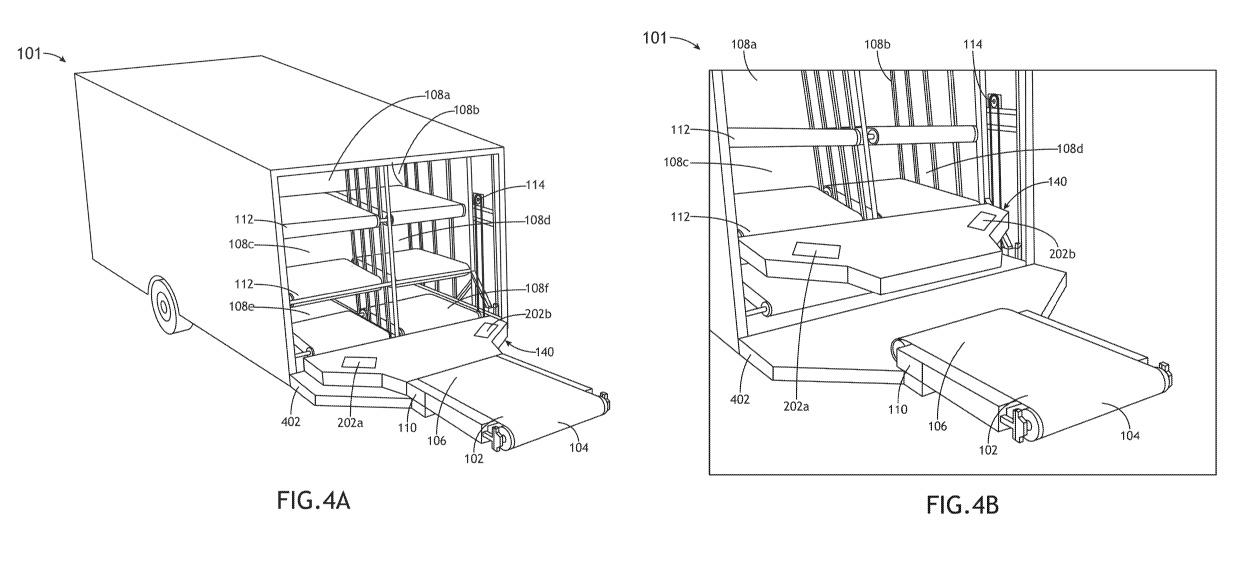
[0038] FIGS. 4A-4B depicts the baggage vehicle 101, in accordance with one
or more embodiments of the present disclosure.
[0039] Although the vertical sorter 114 has been described as being configured
to raise and lower the exterior conveyor 102, this is not intended as a
limitation
on the present disclosure. For example, the exterior conveyor 102 may be
connected to a frame 402. The frame 402 may connect to the storage portion
204. In this regard, the second end 106 of the exterior conveyor 102 may
remain
at a fixed height, while the first end 106 may be configured to raise and
lower
by pivoting about the pivotable connection 110 (e.g., to raise and lower to a
ground height or to an aircraft height). The lateral sorter 140 may be
connected
to the vertical sorter 114 for raising and lowering the height of the lateral
sorter
140.
[0040] For example, the baggage is to be stored in an upper left storage area
of the baggage vehicle 101 (e.g., 108a). The plurality of directional
conveyors
202 may be in a home position at a height of the lowest storage areas (102e
and 102f as depicted in FIG. 3A). Baggage may be conveyed to the plurality of
directional conveyors 202 by the exterior conveyor 102. The vertical sorter
114
may then be engaged to raise the plurality of directional conveyors 202 and
the
baggage to a height of the upper storage areas 102a and 102b (as depicted in
FIG. 4B). The left-hand directional conveyor(s) 202a may then be engaged to
convey the baggage into the front of the upper left storage compartment 108a.
The baggage may then be conveyed from the front of the upper left storage
compartment 108a to the rear by the storage area conveyor 112. The plurality
of directional conveyors 202 may then return to the home position by the
vertical
sorter 114.
[0041] FIGS. 5A-50 illustrates the baggage vehicle 101, in accordance with one
or more embodiments of the present disclosure.
[0042] In embodiments, the lateral sorter 140 includes a secondary conveyor
502 and the horizontal stage 504. The secondary conveyor 502 may be
CA 03153536 2022-03-04
WO 2021/(1465.15
PCT/US2020/049765
configured to load and unload (e.g., a two-way conveyor) the storage areas 108
by any suitable mechanism, such as, but not limited to, a conveyor belt, a
power
roller conveyor, an omni-directional conveyor, or a chain conveyor. The
horizontal stage 504 may be configured to translate the secondary conveyor
502 in a lateral direction by a connection to the secondary conveyor 502. In
this
regard, the secondary conveyor 502 may be translated between the laterally
adjacent storage areas (e.g., 108a, 108b). The horizontal stage 504 may
include any suitable linear stage, including, but not limited to, a rack and
pinion,
a lead screw, a ball screw, a forklift mast, a hoist, or a hydraulic actuator.
The
horizontal stage 504 may also be connected to the vertical sorter 114. In this
regard the secondary conveyor 502 may be positioned to various vertically or
laterally disposed storage areas (e.g., 108a-108d). The secondary conveyor
502 and the horizontal stage may also be controlled by the controller 120.
[0043] For example, the baggage is to be stowed in an upper left storage area
(e.g., 108a) of the baggage vehicle 101. The secondary conveyor 502 may be
in a home position (e.g., a starting position; zero return position) located
at a
bottom right storage area, as depicted in FIG. 5A-B. The baggage may be
conveyed to the secondary conveyor 502 by the exterior conveyor 102. The
vertical sorter 114 may then be engaged to raise the horizontal stage 504, the
secondary conveyor 502, and the baggage to a height of the upper left storage
area (as depicted in FIG. 50). The horizontal stage 504 may then be engaged
to shift the secondary conveyor 502 and the baggage to the front opening of
the upper left storage area. The secondary conveyor 502 may then be engaged
to convey the baggage into the front of the upper left storage compartment.
The
baggage may then be conveyed from the front of the upper left storage
compartment to the rear by the storage area conveyor 112. The secondary
conveyor 502 may then return to the home position by the vertical sorter 114
and the horizontal stage 504.
[0044] FIG. 6 depicts a telescoping exterior conveyor 602, in accordance with
one or more embodiments of the present disclosure.
[0045] In embodiments, the exterior conveyor 102 is configured to telescope
602. The telescoping exterior conveyor 602 may be configured to load and
16
CA 03153536 2022-03-04
WO 2021/(146545
PCT/US2020/049765
unload baggage across a wide range of airplane heights. For example, a
distance between a ground level to an aircraft cargo bin door may be 148
inches. The telescoping exterior conveyor 602 may be telescoped to a
maximum length and pivoted to an angle which is 30 degrees relative to the
ground to reach such height. By way of another example, the telescoping
exterior conveyor 602 may be used to load and unload the baggage from the
ground. The telescoping exterior conveyor 602 may be telescoped to its
shortest length and pivoted to an angle which is -15 degrees relative to the
ground. The telescoping exterior conveyor 602 may be configured to extend
and retract by the controller 120, in accordance with one or more embodiments
of the present disclosure. A telescoping conveyor is disclosed in US Patent
No.
6,431,346, filed on April 5, 2000, which is incorporated herein by reference
in
its entirety.
[0046] In embodiments, the baggage vehicle 101 may use the telescoping
exterior conveyor 602, the pivot connection 110, and the vertical sorter 114
to
maintain the first end 104 of the exterior conveyor 102 at an airplane bay
while
raising the second end 106. The first end 104 may be maintained at the
airplane
bay by retracting the telescoping exterior conveyor 602, raising the exterior
conveyor 602 by the vertical sorter 114, and rotating the first end 104
downwards about the pivot connection 110.
[0047] Although the exterior conveyor 102 has been described as telescoping
602, this is not intended as a limitation on the present disclosure. For
example,
the exterior conveyor 102 may be configured to fold (not depicted). By
folding,
the exterior conveyor 102 may be converted from a load and unload
configuration to a transport configuration. The exterior conveyor may include
a
folding mechanism connecting a first and a second conveyor of the exterior
conveyor. The folding mechanism may fold the first and the second conveyor
together. A folding conveyor is disclosed in US Patent No. 6,708,814, filed on
September 30, 2002, which is incorporated by reference herein it its entirety.
[0048] FIGS. 7A-7B depict a transport configuration of the baggage vehicle
101,
in accordance with one or more embodiments of the present disclosure.
17
CA 03153536 2022-03-04
WO 2021/(146545
PCT/US2020/049765
[0049] In embodiments, the baggage vehicle 101 may include a transport
configuration. The baggage vehicle 101 may have a reduced transport size
when in the transport configuration. The exterior conveyor 102 may be
configured to pivot towards the storage area about the pivotable connection
110. As depicted in FIG. 7A, the baggage vehicle 101 may include an actuator
702. The actuator 702 may be configured to pivot the exterior conveyor 102
between one or more positions, such as, but not limited to, a vertically
stowed
position (e.g., at an angle of 90 degrees relative to the ground), as depicted
in
FIG. 7A. This stowed configuration may reduce a transport size of the baggage
vehicle 101.
[0m] Although the baggage vehicle 101 has been described to include an
actuator 702, this is not intended to be limiting. In this regard, the
exterior
conveyor 102 may be configured to pivot about the pivotable connection 110 in
any suitable manner, such as, but not limited to, a rotary actuator, linear
actuator, hydraulic lift, a pneumatic lift, or a cable winch. Furthermore, the
lateral sorting device (e.g., the plurality of directional conveyors 202) may
also
be configured to pivot to the transport configuration, as depicted in FIG. 7B.
[0051] As discussed in one or more embodiments of the present disclosure, the
exterior conveyor 102 may be configured to telescope or fold. The ability to
telescope or fold the exterior conveyor 102 may provide for a reduced
transport
size of the device while also providing for an exterior conveyor 102 with a
greater working length.
[0052] FIG. 8 depicts a method 800 of sorting baggage into a storage area, in
accordance with one or more embodiments of the present disclosure.
[0053] As shown in FIG. 8, a method 800 includes determining a baggage
associated with a baggage identifier in a step 810, determining a storage area
for the baggage in a step 820, convey the baggage from a first end of the
exterior conveyor to a second end of the exterior conveyor in a step 830,
vertically sort the baggage to a vertical position of the storage area in a
step
840, laterally sort the baggage to a lateral position of the storage area in a
step
850, and convey the baggage within the storage area in a step 860.
18
CA 03153536 2022-03-04
WO 2021/(1465.15
PCT/US2020/049765
[0054] The method 800 may include a step 810, to determine a baggage
associated with a baggage identifier. The step 810 may further include
receiving
the baggage identifier by at least one of an RFID tag, a barcode, or a visual
machine learning algorithm. The baggage identifier may be received from a
component of a baggage vehicle (e.g., baggage vehicle 101) or by a component
separate from the baggage vehicle, such as a handheld reader. In response to
receiving the baggage identifier, the baggage identifier may be looked up in a
database housed on a server (e.g., server 128) by the network connection.
[0055] The method 800 may include a step 820, to determine a storage area
for the baggage. The determination of the storage area for the baggage in the
step 820 may be based on at least one of a dimension, a weight, or a
destination
of the baggage. The determination of the storage area for the baggage in the
step 820 may also be based on a determination that the storage area has room
to receive the baggage. In this regard, the database may include a capacity of
the storage area and a current amount of baggage filling the storage area.
Subtracting the amount of baggage from the capacity may provide an amount
of available space. If the dimensions of the baggage to be received is smaller
than the available space, then the storage area may be determined to be able
to receive the baggage.
[0056] The method 800 may include a step 830, to convey the baggage from a
first end of an exterior conveyor to a second end of an exterior conveyor. The
baggage may be received by the first end of the exterior conveyor from at
least
one of an aircraft, a ground, or a baggage handling area.
[0057] The method 800 may include a step 840, to vertically sort the baggage
to a vertical position of the storage area. The baggage may be vertically
sorted
by any suitable mechanism, such as, but not limited to, a scissor mechanism,
a rack and pinion, a lead screw, a ball screw, forklift mast, a hoist, a
hydraulic
actuator, or a winch and cable.
[0058] The method 800 may include a step 850, to laterally sort the baggage to
a lateral position of the storage area by a horizontal sorter. The baggage may
be vertically sorted by any suitable mechanism, such as, but not limited to, a
19
CA 03153536 2022-03-04
WO 2021/(146545
PCT/US2020/049765
horizontal stage connected to a secondary conveyor, a plurality of directional
conveyors, a diverter, a pusher, or an omni-directional conveyor.
[0059] The method 800 may include a step 860, to convey the baggage within
the storage area. The baggage may be conveyed within the storage area by a
storage area conveyor.
[0060] Similarly, the method 800 may be performed in a reverse direction. In
this regard, baggage stored in the storage area may be conveyed to the first
end of the exterior conveyor.
[0061] FIG. 9 depicts a flow diagram 900, in accordance with one or more
embodiments of the present disclosure.
[0062] In embodiments, the baggage handling system 100 is configured to
execute the flow diagram 900.
[0063] The baggage handling system 100 may be configured to receive a
baggage from a customer 910.
[0064] The baggage handling system 100 may determine a baggage identifier
for the baggage 920. The baggage may have a baggage tag (e.g., an lATA
code) readable by a bar code reader. The bar code may be scanned by the bar
code reader and provided to the system. The system may then identify the
baggage by comparing the scanned bar code with a database of known
baggage bar codes.
[0065] The baggage handling system 100 may then lookup the baggage
identifier in a database to determine a flight associated with the baggage
930.
[0066] If the baggage does not have a known flight, the baggage handling
system 100 may notify a baggage handler 945.
[0067] If the baggage has a known flight, the baggage handling system 100
may convey the baggage to an appropriate handling area 940. The baggage
may be conveyed by one or more conveyors (further depicted in FIG. 10). The
appropriate handling area may be associated with the flight.
CA 03153536 2022-03-04
WO 2021/(146545
PCT/US2020/049765
[0068] The baggage handling system 100 may then determine an appropriate
storage area of a storage vehicle 950. The storage vehicle may include the
baggage vehicle 101. The determining an appropriate storage area of the
storage vehicle 950 may be based on a sorting scheme. The sorting scheme
may include one or more factors which are evaluated when determining the
appropriate storage area 950. The sorting scheme may include a factor of the
storage area has an open spot for the baggage (e.g., the storage area is not
full of other baggage). The sorting scheme may include a factor of at least
one
of a dimension, weight, or destination of the baggage. The sorting scheme may
include a factor of a passenger status of a passenger associated with the
baggage (e.g., a first-class customer may receive preferential storage
treatment). The sorting scheme may include a factor of a type of the baggage
(e.g., breakable baggage may get preferential storage treatment; US mail may
be conveyed to a US mail storage area, etc.). The sorting scheme include a
factor of a flight delay time of a flight associated with the baggage. The
sorting
scheme may further be evaluated by a process improvement algorithm (not
depicted). The process improvement algorithm may be configured to estimate
an optimal storage area of a plurality of storage vehicle based on the baggage
flight data and a current baggage status of the plurality of storage vehicle.
In
this regard, the baggage may be sorted to a storage area to reduce a time
until
the baggage reaches the airplane and/or the terminal.
[0069] If the baggage handling system 100 determines there is no available
storage area, the system 100 may provide a notification to a baggage handler
965.
[0070] If the baggage handling system 100 determines a storage area is
available, the baggage may be conveyed to the storage area 960. The baggage
may be conveyed to the storage area, in accordance with one or more
embodiments of the present disclosure. For example, the storage vehicle may
include one or more of an exterior conveyor, a lateral sorter, a vertical
sorter,
and a storage area conveyor.
[0071] The baggage handling system 100 may then move the storage vehicle
to an aircraft associated with the flight by an autonomous control 970. The
21
CA 03153536 2022-03-04
WO 2021/(146545
PCT/US2020/049765
autonomous control 970 may be performed by one or more propulsion units on
the storage vehicle. The autonomous control 970 may be a level of autonomous
driving, such as, but not limited to an SAE level 0 to 5 system. For example,
the
autonomous control 970 may provide a warning and intervention control (e.g.,
autonomous braking), in accordance with a level 0 system. By way of another
example, the autonomous control 970 may provide a driver assist (e.g., parking
assist), in accordance with a level 1 system. By way of another example, the
autonomous control 970 may include fully autonomous driving with no steering
wheel required to operate the device, in accordance with a level 5 system. Any
of the various SAE levels of autonomous control described can be performed
by the controller 120. The autonomous control 970 may be based on data from
various sensors, such as, but not limited to, location tracking sensors (e.g.,
a
global positioning circuitry) or one or more vehicle sensors (e.g., an
automatic
parking sensor, a backup collision sensor, an intelligent parking assist
sensor,
etc.). The autonomous control 970 may be facilitated by a communication with
one or more airplanes (e.g., by a wireless network in RF frequency). The
autonomous control 970 may be based on a preset map of the airport with one
or more drive paths.
[0072] FIG. 10 depicts the baggage vehicle 101 receiving a baggage 1006 from
a conveyor 1002, in accordance with one or more embodiments of the present
disclosure.
[0073] In embodiments, the baggage vehicle 101 is configured to receive
baggage from the conveyor 1002. The conveyor 1002 depicted is merely
illustrative. The conveyor 1002 may be a component of an aircraft baggage
handling system (e.g., system 100 depicted by flow diagram 900). The system
100 may selectively convey the baggage 1006 to the conveyor 1002, according
to any method known in the art. The baggage may then be conveyed by the
conveyor 1002 to the baggage vehicle 101. FIG. 10 depicts a diverter 1004 as
diverting the baggage to the baggage vehicle 101, but this is not intended to
be
limiting. The baggage vehicle 101 may receive the baggage from the conveyor
1002 by a first end 106 of the exterior conveyor 102. The baggage vehicle 101
22
CA 03153536 2022-03-04
WO 2021/(1465.15
PCT/US2020/049765
may then sort the baggage to a selected storage area 108, in accordance with
one or more embodiments of the present disclosure.
[0074] FIG. 11 depicts a first baggage vehicle 101a unloading baggage to a
second baggage vehicle 101b and a third baggage vehicle 101c, in accordance
with one or more embodiments of the present disclosure.
[0075] In embodiments, the baggage vehicle 101a may include a baggage (e.g.,
baggage 1006) in a storage area 108 of the baggage vehicle 101a. The
baggage vehicle 101a may unload the baggage by engaging the storage area
conveyor 112 and conveying the baggage through the rear opening 304 (further
depicted in FIG. 30). If the device includes the rear opening cover 302, the
rear
opening cover 302 must be raised before the baggage may be conveyed
through the rear opening 304. The second baggage vehicle 101b may be
moved to the rear opening 304. Similarly, the third baggage vehicle 101c may
be moved to another rear opening 304. In this regard, the first baggage
vehicle
101a may be considered a sorting device and the second and third baggage
vehicle 101b, 101c may be considered a receiving device. The description of
sorting and receiving devices is not intended to be limiting. For example, any
of
the baggage vehicle 101a, 101b, or 101c may be configured to sort baggage
from a rear opening and receive baggage by an exterior conveyor 102.
Furthermore, as depicted in FIG. 11, the second and/or third baggage vehicles
101b, 101c, may be positioned in various configurations at the rear of the
first
baggage vehicle 101a, such as, but not limited to, parallel to the first
baggage
vehicle 101a or perpendicular to the first baggage vehicle 101a.
[0076] The first, second, and third baggage vehicles 101a-101c may also be
controlled by the baggage system 100 (e.g., by a controller of the system
100).
In this regard, the system 100 may determine that a baggage held by the first
baggage vehicle 101a should be on a certain flight. The second baggage
vehicle 101b may be associated with this flight. The system 100 may sort the
baggage from the first baggage vehicle 101a to the second baggage vehicle
101b by engaging the storage area conveyor 112 of the first baggage vehicle
101a. Then the baggage may be sorted to a storage area 108 on the second
device associated with the baggage destination.
23
CA 03153536 2022-03-04
WO 2021/046545
PCT/US2020/049765
[0077] Although the baggage vehicle 101 a is described as unloading the
baggage by the rear opening 304, this is not intended as a limitation on the
present disclosure. As discussed in one or more embodiments of the present
disclosure, the secondary conveyor 112 and the exterior conveyor 102 may be
a two-way conveyor. In this regard, the baggage vehicle 101a may unload the
baggage from the storage area 108 by engaging the storage area conveyor 112
and the exterior conveyor 102 in a reverse direction.
[0078] FIG. 12 depicts the system 100, in accordance with one or more
embodiments of the present disclosure.
[0079] As discussed, the system 100 may include the baggage vehicle 101
which is connected to the server 128 by the network 126. The system 100 may
further include one or more secondary devices 1202. The secondary device
1202 may be connected to the server 128 by the network 126.
[0080] The secondary device 1202 may include the conveyor 1002 or the
diverter 1004. In this regard, conveyor 1002 and the diverter 1004 may
communicate with the server 128 regarding the baggage being conveyed by
the conveyor 1002 and diverted by the diverter 1004. The server 128 may then
communicate this information to the baggage vehicle 101 by way of the network
126.
[0081] The secondary device 1202 may also include the second baggage
vehicle 101b and the third baggage vehicle 101c. In this regard, the system
100
may perform various loading and unloading operations depicted in FIG. 11.
Each of the baggage vehicles 101a-101c may be configured to communicate
by way of the network 126. In this regard, the system 100 may include a
plurality
of baggage vehicles 101.
[0082] Referring generally to FIGS. 1A-12, the baggage handling system 100 is
disclosed.
[0083] Although the lateral sorter 140 described in FIGS. 1A-2B is described
as
being either the secondary conveyor 502 connected to the horizontal stage 504
or the plurality of directional conveyors 202, this is not intended as a
limitation
24
CA 03153536 2022-03-04
WO 2021/046545
PCT/US2020/049765
on the present disclosure. For example, the lateral sorter 140 may include any
suitable mechanism, such as, but not limited to, a diverter, a pusher, or an
omni-
directional wheel.
[0084] In embodiments, the lateral sorter 140 of the baggage vehicle 101
includes the diverter (not depicted). The diverter may pivot between one or
more positions by an electronic or pneumatic drive. The diverter may then
divert
baggage from the conveyor to one or more secondary conveyors (e.g.,
secondary conveyor 502). The diverter may be pneumatic or electric.
Furthermore, the diverter may be controlled by the controller 120, in
accordance
with one or more embodiments of the present disclosure. A diverter is
described
in US Patent No. 4,711,357, filed on December, 18, 1985, which is incorporated
herein by reference in its entirety.
[0085] In embodiments, the lateral sorter 140 of the baggage vehicle 101
includes the pusher (not depicted) and the secondary conveyor 502. The
secondary conveyor 502 may span a width of the storage areas 108. The
pusher may be disposed above the secondary conveyor 502. The pusher may
be actuated by any suitable mechanism, such as, but not limited to, a
hydraulic
actuator or a cam. The pusher may be controlled by the controller 120, in
accordance with one or more embodiments of the present disclosure. The
controller may actuate the pusher to push the baggage in a lateral direction
along the secondary conveyor 502 (e.g., to push luggage between the laterally
adjacent storage areas). A pusher is described in US Patent No. 6,837,359,
filed on February 17, 2004, which is incorporated herein by reference in its
entirety.
[0086] The pusher may also be connected to the vertical sorter 114. In this
regard the pusher may be raised with the secondary conveyor 502 as the
secondary conveyor is raised (e.g., to the storage area 108). The pusher may
then laterally sort the luggage by engaging the pusher and pushing the luggage
laterally along the secondary conveyor. Alternatively, the pusher may be
connected to the device by a connection other than to the vertical sorter
(e.g.,
to the storage portion or to the exterior conveyor 102). In this regard, the
pusher
may remain stationary as the secondary conveyor 502 is changed to a height
CA 03153536 2022-03-04
WO 2021/(1465.15
PCT/US2020/049765
of the storage area 108 by the vertical sorter. The baggage may be laterally
pre-sorted on the secondary conveyor 502 by the pusher before the height of
the secondary conveyor 502 is changed.
[0087] In embodiments, the lateral sorter 140 of the baggage vehicle 101
includes any suitable mechanism for laterally sorting baggage between lateral
storage areas 108. For example, the lateral sorter 140 may include an omni-
directional wheel (not depicted).
[0088] In embodiments, the storage areas 108 of the baggage vehicle 101 may
be associated with categories of items to be stored. For example, much of the
present disclosure has discussed the storage of baggage in the storage areas
108. This is not intended as a limitation on the present disclosure. In this
regard,
baggage should be interpreted to include various cargo types, such as, but not
limited to, general cargo, special cargo, freight, consumer baggage, or US
mail.
[0089] Although the storage areas 108 has been described as including the
storage area conveyors 112, this is not intended as a limitation on the
present
disclosure. For example, the storage area 108 may include one or more rollers
(not depicted). In this regard, the baggage may be loaded into the storage
area
108 and rolled into the rear of the storage area 108. The storage area 108 may
then be unloaded by pushing and/or pulling the baggage along the rollers.
[0090] As depicted in FIG. 3A-5C, the baggage vehicle 101 may include three
rows of vertically adjacent storage areas 108 with two columns of laterally
adjacent storage areas 108 (totaling six storage areas). This depiction is not
intended to be limiting. In this regard, the device may include any number of
rows and columns of storage areas. Furthermore, the storage areas may
include different sized storage areas (e.g., a double tall storage area, a
double
wide storage area, etc.). By including different sized storage areas, larger
items
may be stored by the device, such as skis or golf clubs.
[0091] In embodiments, the baggage vehicle 101 includes one or more sensors
(not depicted). The sensors may be configured to identify the baggage (e.g.,
by
an RFID tag, by a barcode, by a visual machine learning algorithm, etc.). The
sensor may include any suitable sensor, such as, but not limited to, an RFID
26
CA 03153536 2022-03-04
WO 2021/046545
PCT/US2020/049765
sensor, a barcode scanner, or a computer vision sensor (with a visual
identifier).
For example, the sensor may include a barcode scanner configured to scan a
tag of the baggage. The tag may include a barcode of the baggage
identification. The barcode may be stored in a database of baggage, the
database including various data regarding the baggage, such as, but not
limited
to, an owner of the baggage, a destination of the baggage, flight details of
the
owner, a seat number of the owner, a priority of the baggage, a connecting
time
of the owner, a zip code of the owner, a color of the baggage, or a weight of
the
baggage. A baggage handler may scan the barcode or the baggage vehicle
101 may scan the barcode autonomously. Scan data may then be provided to
the controller 120. The controller 120 may determine that the baggage should
be stored in a storage area 108 based on the flight details (e.g., storage
area
108a is currently being used for flights to Los Angeles). The controller 120
may
then control the device autonomously to store the baggage in the appropriate
storage area 108 by the vertical sorter 114 and the lateral sorter. Although
the
baggage vehicle 101 has been described as including a sensor, this is not
intended as a limitation on the present disclosure. For example, the
controller
120 may receive a baggage identifier by a communication with the server 128.
[0092] Although the baggage vehicle 101 is described with the home position
being the bottom storage areas 108e, 108f, this is not intended as a
limitation
on the present disclosure. For example, the home position may be located on
any lateral and vertical position of the device. The home position may be
optimized to reduce a travel time between the home position and each of the
storage areas. In this regard, a centralized home position may have a
minimized travel time.
[0093] In embodiments, the baggage vehicle 101 may include one or more
digital displays (e.g., LED, OLED and the like) formed/attached to one or more
surfaces of the device (e.g., top surface) for message/advertising purposes.
[0094] Although the vertical sorter 114 has been described as vertically
sorting
baggage between one or more vertically adjacent storage areas (e.g., 108a-
1080. This is not intended to be limiting. In this regard, vertical sorter 114
may
be configured to vertically sort baggage within a single storage area 108 by a
27
CA 03153536 2022-03-04
WO 2021/046545
PCT/US2020/049765
connection to the lateral sorter 140 (not depicted). For example, the storage
area 108 may include a first baggage on a floor height of the storage area
108.
The baggage vehicle 101 may then receive a second baggage. The vertical
sorter 114 may raise the second baggage to a height which is above the first
baggage (e.g., based on the height of the first baggage). The second baggage
may then be placed on the first baggage by the lateral sorter 140.
[0095] The baggage vehicle 101 has been described as a baggage vehicle with
a propulsion unit 134 to move the baggage vehicle 101 by one or more wheels
136. This is not intended as a limitation on the present disclosure. For
example,
the baggage vehicle 101 may be configured to couple with an exterior
propulsion unit (not depicted), such as, but not limited to, a tug. The
baggage
vehicle 101 may be configured to couple in any suitable manner, such as, but
not limited to, a pintle hitch trailer connection (not depicted). In this
regard, the
baggage vehicle 101 may be deployed to a baggage handling area by a
baggage handler controlling the baggage vehicle 101 by the baggage tug.
[0096] The one or more processors of the control system may include any one
or more processing elements known in the art. In general, the term "processor"
may be broadly defined to encompass any device having one or more
processing elements, which execute program instructions from a non-transitory
memory medium. The one or more processors may include any
microprocessor-type device configured to execute software algorithms and/or
program instructions. In one embodiment, the one or more processors may be
configured to execute a set of program instructions to carry out one or more
steps described throughout the present disclosure. It should be recognized
that
the steps described throughout the present disclosure may be carried out by a
single control system or, alternatively, multiple control systems. The memory
may include any storage medium known in the art suitable for storing program
instructions executable by the associated one or more processors of control
system. For example, the memory may include, but is not limited to, a read-
only memory, a random-access memory, a solid-state drive and the like. In
another embodiment, it is noted herein that the memory is configured to store
28
CA 03153536 2022-03-04
WO 2021/046545
PCT/US2020/049765
one or more results from the one or more of the various sub-systems of the
system.
[0097] In some implementations described herein, logic and similar
implementations may include software or other control structures. Electronic
circuitry, for example, may have one or more paths of electrical current
constructed and arranged to implement various functions as described herein.
In some implementations, one or more media may be configured to bear a
device-detectable implementation when such media hold or transmit device-
detectable instructions operable to perform as described herein. In some
variants, for example, implementations may include an update or modification
of existing software or firmware, or of gate arrays or programmable hardware,
such as by performing a reception of or a transmission of one or more
instructions in relation to one or more operations described herein.
Alternatively
or additionally, in some variants, an implementation may include special-
purpose hardware, software, firmware components, and/or general-purpose
components executing or otherwise invoking special-purpose components.
Specifications or other implementations may be transmitted by one or more
instances of tangible transmission media as described herein, optionally by
packet transmission or otherwise by passing through distributed media at
various times.
[0098] Alternatively, or additionally, implementations may include executing a
special-purpose instruction sequence or invoking circuitry for enabling,
triggering, coordinating, requesting, or otherwise causing one or more
occurrences of virtually any functional operations described herein. In some
variants, operational or other logical descriptions herein may be expressed as
source code and compiled or otherwise invoked as an executable instruction
sequence.
[0099] One skilled in the art will recognize that the herein described
components operations, devices, objects, and the discussion accompanying
them are used as examples for the sake of conceptual clarity and that various
configuration modifications are contemplated. Consequently, as used herein,
the specific exemplars set forth and the accompanying discussion are intended
29
CA 03153536 2022-03-04
WO 2021/046545
PCT/US2020/049765
to be representative of their more general classes. In general, use of any
specific exemplar is intended to be representative of its class, and the non-
inclusion of specific components, operations, devices, and objects should not
be taken as limiting.
gm 00] As used herein, directional terms such as "top," "bottom," "over,"
"under,"
"upper," "upward," "lower," "down,- and "downward" are intended to provide
relative positions for purposes of description, and are not intended to
designate
an absolute frame of reference. Various modifications to the described
embodiments will be apparent to those with skill in the art, and the general
principles defined herein may be applied to other embodiments
[00 101] Wth respect to the use of substantially any plural and/or singular
terms
herein, those having skill in the art can translate from the plural to the
singular
and/or from the singular to the plural as is appropriate to the context and/or
application. The various singular/plural permutations are not expressly set
forth
herein for sake of clarity.
[00102]The herein described subject matter sometimes illustrates different
components contained within, or connected with, other components. It is to be
understood that such depicted architectures are merely exemplary, and that in
fact many other architectures can be implemented which achieve the same
functionality. In a conceptual sense, any arrangement of components to
achieve the same functionality is effectively "associated" such that the
desired
functionality is achieved. Hence, any two components herein combined to
achieve a particular functionality can be seen as "associated with" each other
such that the desired functionality is achieved, irrespective of architectures
or
intermedial components. Likewise, any two components so associated can also
be viewed as being "connected," or "coupled," to each other to achieve the
desired functionality, and any two components capable of being so associated
can also be viewed as being "couplable," to each other to achieve the desired
functionality. Specific examples of couplable include but are not limited to
physically mateable and/or physically interacting components and/or wirelessly
interactable and/or wirelessly interacting components and/or logically
interacting and/or logically interactable components.
CA 03153536 2022-03-04
WO 2021/(146545
PCT/US2020/049765
[00103] Furthermore, it is to be understood that the invention is defined by
the
appended claims. It will be understood by those within the art that, in
general,
terms used herein, and especially in the appended claims (e.g., bodies of the
appended claims) are generally intended as "open" terms (e.g., the term
"including" should be interpreted as "including but not limited to," the term
"having" should be interpreted as "having at least," the term "includes"
should
be interpreted as "includes but is not limited to," and the like). It will be
further
understood by those within the art that if a specific number of an introduced
claim recitation is intended, such an intent will be explicitly recited in the
claim,
and in the absence of such recitation no such intent is present. For example,
as an aid to understanding, the following appended claims may contain usage
of the introductory phrases "at least one" and "one or more" to introduce
claim
recitations. However, the use of such phrases should not be construed to imply
that the introduction of a claim recitation by the indefinite articles "a" or
"an"
limits any particular claim containing such introduced claim recitation to
inventions containing only one such recitation, even when the same claim
includes the introductory phrases "one or more" or "at least one" and
indefinite
articles such as "a" or "an" (e.g., "a" andlor "an" should typically be
interpreted
to mean "at least one" or "one or more"); the same holds true for the use of
definite articles used to introduce claim recitations. In addition, even if a
specific
number of an introduced claim recitation is explicitly recited, those skilled
in the
art will recognize that such recitation should typically be interpreted to
mean at
least the recited number (e.g., the bare recitation of "two recitations,"
without
other modifiers, typically means at least two recitations, or two or more
recitations). Furthermore, in those instances where a convention analogous to
"at least one of A, B, and C, and the like" is used, in general such a
construction
is intended in the sense one having skill in the art would understand the
convention (e.g., "a system having at least one of A, B, and C" would include
but not be limited to systems that have A alone, B alone, C alone, A and B
together, A and C together, B and C together, and/or A, B, and C together, and
the like). In those instances where a convention analogous to "at least one of
A, B, or C, and the like" is used, in general such a construction is intended
in
the sense one having skill in the art would understand the convention (e.g.,"
a
system having at least one of A, B, or C" would include but not be limited to
31
CA 03153536 2022-03-04
WO 2021/(1465.15
PCT/US2020/049765
systems that have A alone, B alone, C alone, A and B together, A and C
together, B and C together, and/or A, B, and C together, and the like). It
will be
further understood by those within the art that virtually any disjunctive word
and/or phrase presenting two or more alternative terms, whether in the
description, claims, or drawings, should be understood to contemplate the
possibilities of including one of the terms, either of the terms, or both
terms. For
example, the phrase -A or B" will be understood to include the possibilities
of
"A" or "B" or "A and B."
[mum] It is believed that the present disclosure and many of its attendant
advantages will be understood by the foregoing description, and it will be
apparent that various changes may be made in the form, construction and
arrangement of the components without departing from the disclosed subject
matter or without sacrificing all of its material advantages. The form
described
is merely explanatory, and it is the intention of the following claims to
encompass and include such changes. Furthermore, it is to be understood that
the invention is defined by the appended claims
32