Language selection

Search

Patent 3153694 Summary

Third-party information liability

Some of the information on this Web page has been provided by external sources. The Government of Canada is not responsible for the accuracy, reliability or currency of the information supplied by external sources. Users wishing to rely upon this information should consult directly with the source of the information. Content provided by external sources is not subject to official languages, privacy and accessibility requirements.

Claims and Abstract availability

Any discrepancies in the text and image of the Claims and Abstract are due to differing posting times. Text of the Claims and Abstract are posted:

  • At the time the application is open to public inspection;
  • At the time of issue of the patent (grant).
(12) Patent Application: (11) CA 3153694
(54) English Title: SPARK IGNITED PILOT FOR GAS BURNER
(54) French Title: PILOTE ALLUME A ETINCELLE POUR UN BRULEUR A GAZ
Status: Examination Requested
Bibliographic Data
(51) International Patent Classification (IPC):
  • F23Q 3/00 (2006.01)
  • F23Q 9/00 (2006.01)
(72) Inventors :
  • RUSH, RICHARD III (United States of America)
  • MARTELLE, THOMAS A. (United States of America)
(73) Owners :
  • SOLARONICS, INC. (United States of America)
(71) Applicants :
  • SOLARONICS, INC. (United States of America)
(74) Agent: SMART & BIGGAR LP
(74) Associate agent:
(45) Issued:
(22) Filed Date: 2022-03-30
(41) Open to Public Inspection: 2022-11-28
Examination requested: 2023-12-11
Availability of licence: N/A
(25) Language of filing: English

Patent Cooperation Treaty (PCT): No

(30) Application Priority Data:
Application No. Country/Territory Date
17/333,076 United States of America 2021-05-28

Abstracts

English Abstract


A spark ignited, gas fueled pilot assembly compromising a bracket and a metal
gas tube
extending through the bracket and having an outlet end. The gas tube is
surrounded by a ceramic
jacket which is of such a length as to extend beyond the outlet end of the gas
tube by approximately
.03" such that the gas tube outlet is recessed into the ceramic jacket. The
assembly further
comprises a pair of ignitor electrodes carried by the bracket and arranged and
located relative to
the recessed gas supply tube to ignite fuel emanating therefrom.


Claims

Note: Claims are shown in the official language in which they were submitted.

WHAT IS CLAIMED:
1. A spark ignited, gas fueled pilot assembly comprising:
a support member;
a metal gas tube extending through and carried by the support member and
haying an outlet
end;
a ceramic jacket attached directly and surroundingly to the gas tube between
the support
member and the outlet end, the ceramic jacket extending beyond the outlet end
of the gas tube
whereby the gas tube end is recessed into the ceramic jacket; and
the assembly further comprising a set of spark gap electrodes carried by the
support
member and configured and located to ignite gas emanating from the gas tube.
2. A spark ignited, gas fueled pilot assembly as defined in claim 1 wherein
the jacket
is made of alumina.
3. A spark-ignited, gas-fueled pilot assembly as defined in claim 2 wherein
the
ceramic jacket is tubular and sunoundingly contacts the outer surface of the
gas supply tube.
4. A spark -ignited, gas -fueled pilot assembly as defined in claim 1
wherein the
ceramic jacket extends approximately .030" beyond the outlet end of the gas
tube.
5. An infrared radiator/burner comprising:
a burner assembly haying a plenum chamber with a fuel/air mixture inlet and a
radiator
panel attached to the plenum and haying an exposed surface; the combination
further comprising
4

a spark -ignited, gas -fueled pilot assembly as defined in claim I attached to
the plenum chamber
and located in spaced relationship with the radiator panel to ignite a fuel
air mixture passing
therethrough.

Description

Note: Descriptions are shown in the official language in which they were submitted.


SPARK IGNITED PILOT FOR GAS BURNER
FIELD OF THE INVENTION
[0001] The device described herein is in the field of spark ignited
pilots for gas fueled
burners.
BACKGROUND OF THE DISCLOSURE
[0002] Gas fired pilots are commonly used to start gas fired infrared
burners used in food
preparation as well as other applications. A typical pilot includes a metal
gas supply tube mounted
in association with a pair of electrodes forming a spark gap immediately above
the gas tube outlet.
Applying a voltage to one of the two electrodes while grounding the other can
produce a spark in
the gap thereby igniting gas coming from the tube.
BRIEF SUMMARY OF THE DISCLOSURE
[0003] This document describes a spark-ignited, gas-fueled pilot that may
be used in
combination with a gas fired burner wherein the pilot includes a bracket
providing a mount for
pair of spark gap electrodes as well as a metal gas supply tube and further
wherein the metal gas
supply tube is jacketed by a ceramic tube that is longer than the portion of
the gas tube extending
above the bracket surface. By virtue of this combination, the gas supply tube
is recessed into the
ceramic jacket, the result being a significant increase in the useful life of
the pilot. As used herein,
the term "gas" shall be construed to mean natural gas, propane, and other
commonly available
flammable gaseous products.
BRIEF DESCRIPTION OF THE DRAWINGS
[0004] The features and advantages of the invention described herein will
become more
apparent from a reading of the following description of an illustrative
embodiment, taken with the
attached to-scaled drawings of which:
{YB:01259385.DOCX } 1
Date Recue/Date Received 2022-03-30

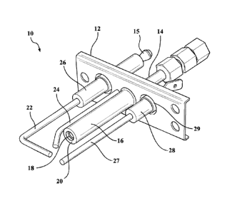
[0005] FIG. 1 is a view of an exemplary pilot assembly including a
mounting bracket,
spark gap igniter electrodes, a jacketed gas supply tube and a sensor probe;
[0006] FIG. 2 is a sideview of the pilot assembly partly sectioned to
show the recess of
the gas tube relative to the surrounding ceramic jacket; and
[0007] FIG. 3 is a perspective view of an infrared gas fire burner as an
illustration of how
the pilot assembly can be found in an industrial application.
DETAILED DESCRIPTION OF THE ILLUSTRATIVE EMBODIMENT
[0008] Referring to FIGS. 1 and 2, a gas-fired, spark-ignited pilot
assembly 10 is shown to
comprise a metal support member in the form of a bracket 12. Extending through
and carried by
the bracket 12 is a small diameter gas supply tube 14 having a surrounding
ceramic jacket 16 in
direct contacting association therewith. As best shown in FIG. 2, the jacket
16 rests on the top
surface of the bracket and has a length which is greater than the length of
the gas supply tube above
the surface of the bracket 12 such that the outlet end 18 of the gas supply
tube is recessed into the
jacket 16 and below the top surface thereof by appropriately .030". The bottom
edge of the ceramic
jacket is sealed around the joint with the bracket surface as shown.
[0009] A spark gap ignitor for the pilot assembly 10 comprises an L-
shaped high voltage
electrode 22 and a grounded electrode 24 arranged relative to the electrode 22
so as to define a
spark gap which is close to the outlet of the pilot gas tube 14 and the top of
the jacket 16. The
high voltage electrode 22 is mounted within a ceramic insulator 26 which
extends through and is
attached to the bracket 12 with a suitable connector 15 for attachment to a
high voltage supply.
[0010] The assembly 10 further comprises a sensor probe 27 of heat
sensitive metal
extending through a ceramic insulator 28 which is attached to and extends
through the bracket 12.
The probe 27 is known in the art and senses heat from the pilot assembly when
it is active; i.e. that
{YB:01259385 DOCX } 2
Date Recue/Date Received 2022-03-30

the gas being emitted from the end of the tube 14 and jacket 16 and has been
ignited and is burning.
The ceramic jacket 16 does not serve any purpose as an insulator, does not
extend through the
bracket 12, but, rather, is sealingly attached to the top planar surface
thereof. The inside diameter
of the jacket 16 is such as to produce a close fit with the gas supply tube
14.
[0011] The preferred ceramic for the jacket 16 is alumina but other
ceramics such as Si203
can also be used. The outside diameter of the ceramic jacket 16 is on the
order of 3/8" whereas the
outside diameter of the gas tube 14 is on the order of 3/16", these dimensions
being representative
of a typical device and not intended to be limiting. The recess is on the
order of .030" in a pilot
assembly having the aforementioned dimensions.
INDUSTRIAL APPLICABILITY
[0012] FIG. 3 shows in perspective an infrared burner 30 having a
generally rectangular
metal housing 32 with an inlet 34 for a fuel/air mixture. The housing 32 makes
up a plenum
chamber in which the fuel and air are thoroughly mixed and are emitted
upwardly and outwardly
through a assembly comprising a porous open cell medium 36 through which the
distributed
fuel/air mixture passes and is ignited by the pilot assembly 10 which is shown
attached by means
of the bracket 12 to a side of the housing 32 with the gas tube, outlet and
the ignitor electrodes
located close to the surface of the medium 36. A more detailed description of
the burner 30 can
be found in the co-pending application serial number 16/454,509 filed June 27,
2019 and entitled
"Gas-fired Infrared Burner", the complete disclosure of which is incorporated
herein by reference.
It is to be understood that the inventive subject matter of this document is
and has been described
with reference to an illustrative embodiment and various modifications and
additions to the
embodiment may be made to fit a particular application.
{YB:01259385 DOCX } 3
Date Recue/Date Received 2022-03-30

Representative Drawing
A single figure which represents the drawing illustrating the invention.
Administrative Status

For a clearer understanding of the status of the application/patent presented on this page, the site Disclaimer , as well as the definitions for Patent , Administrative Status , Maintenance Fee  and Payment History  should be consulted.

Administrative Status

Title Date
Forecasted Issue Date Unavailable
(22) Filed 2022-03-30
(41) Open to Public Inspection 2022-11-28
Examination Requested 2023-12-11

Abandonment History

There is no abandonment history.

Maintenance Fee

Last Payment of $125.00 was received on 2024-03-22


 Upcoming maintenance fee amounts

Description Date Amount
Next Payment if standard fee 2025-03-31 $125.00
Next Payment if small entity fee 2025-03-31 $50.00

Note : If the full payment has not been received on or before the date indicated, a further fee may be required which may be one of the following

  • the reinstatement fee;
  • the late payment fee; or
  • additional fee to reverse deemed expiry.

Patent fees are adjusted on the 1st of January every year. The amounts above are the current amounts if received by December 31 of the current year.
Please refer to the CIPO Patent Fees web page to see all current fee amounts.

Payment History

Fee Type Anniversary Year Due Date Amount Paid Paid Date
Application Fee 2022-03-30 $407.18 2022-03-30
Request for Examination 2026-03-30 $816.00 2023-12-11
Maintenance Fee - Application - New Act 2 2024-04-02 $125.00 2024-03-22
Owners on Record

Note: Records showing the ownership history in alphabetical order.

Current Owners on Record
SOLARONICS, INC.
Past Owners on Record
None
Past Owners that do not appear in the "Owners on Record" listing will appear in other documentation within the application.
Documents

To view selected files, please enter reCAPTCHA code :


To view images, click a link in the Document Description column. To download the documents, select one or more checkboxes in the first column and then click the "Download Selected in PDF format (Zip Archive)" or the "Download Selected as Single PDF" button.

List of published and non-published patent-specific documents on the CPD .

If you have any difficulty accessing content, you can call the Client Service Centre at 1-866-997-1936 or send them an e-mail at CIPO Client Service Centre.


Document
Description 
Date
(yyyy-mm-dd) 
Number of pages   Size of Image (KB) 
New Application 2022-03-30 7 265
Abstract 2022-03-30 1 14
Claims 2022-03-30 2 38
Description 2022-03-30 3 133
Drawings 2022-03-30 2 62
Representative Drawing 2023-05-03 1 13
Cover Page 2023-05-03 1 41
Request for Examination / Amendment 2023-12-11 6 156
Claims 2023-12-11 1 43