Note: Descriptions are shown in the official language in which they were submitted.
CA 03153695 2022-03-08
WO 2021/050486 PCT/US2020/049849
PRESSURE RELIEF DEVICE
DESCRIPTION
Field of the Disclosure
[001] This disclosure is directed to the field of pressure relief devices.
More
particularly, the disclosure relates to pressure relief vents, burst panels,
rupture disks,
or other devices designed to open during an explosion or in response to a pre-
determined pressure differential to reduce damage.
Background of the Disclosure
[002] Pressure relief devices are commonly used as safety devices in systems
containing pressurized fluids in gas or liquid form, or in contained systems
containing
volatile (e.g., flammable) conditions that may lead to a potentially dangerous
increase
in pressure. A pressure relief device will vent fluid from a system when the
pressure in
the system reaches a predetermined level¨usually before it reaches an unsafe
level.
One category of pressure relief device¨a membrane pressure relief
device¨includes,
e.g., rupture disks and burst panels, also known as explosion vents.
[003] It may be desirable for a membrane pressure relief device to exhibit
resistance to reverse-pressure (e.g., a partial- or full-vacuum condition) in
the event of
a pressure drop within the enclosed system. One example of a rectangular flat-
panel
explosion vent may be provided with some resistance to reverse pressure by way
of a
diagonal (e.g., X-shaped) pattern of creases. Such creases may provide slight
rigidity
and slight vacuum resistance. Such vents are typically rated for pressures up
to
around 0.1 bar and have a vacuum resistance of 0.05 bar¨less than the rated
set
pressure of the vent. Another example of a flat-panel explosion vent may be
provided
1
CA 03153695 2022-03-08
WO 2021/050486 PCT/US2020/049849
with some resistance to reverse pressure by way of "skeletal-type" bulges
and/or rib-
like features oriented parallel to a perimeter of the vent. Once again, such
vents are
typically rated for pressures up to around 0.1 bar and have a vacuum
resistance of
0.05 bar¨less than the rated set pressure of the vent.
[004] The present disclosure recognizes a need for a membrane pressure
relief device with improved vacuum resistance, particularly in a membrane
pressure
relief device having no secondary member as a vacuum support. The present
disclosure provides one or more of these, and/or other, advantages.
BRIEF DESCRIPTION OF THE DRAWINGS
[005] The accompanying drawings, which are incorporated in and constitute a
part of this specification, illustrate several embodiments of the disclosure
and together
with the description, serve to explain the principles of the disclosure.
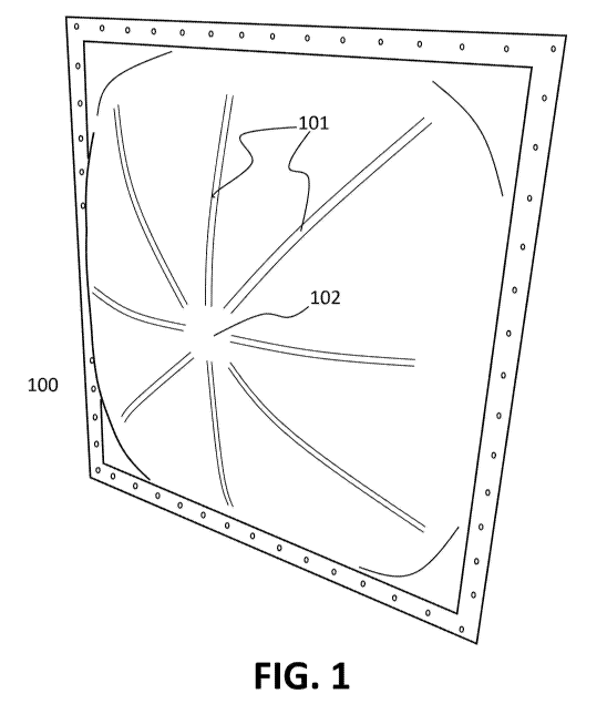
[006] FIG. 1 is an illustration of a membrane pressure relief device in the
form
of a compound-dome explosion vent with radial rib structures;
[007] FIG. 2 illustrates another embodiment of a domed square explosion vent
having radial rib structures;
[008] FIG. 3 illustrates an embodiment of a rectangular domed explosion vent
having ribbed structures;
[009] FIG. 4 illustrates an embodiment of a round domed explosion vent
having ribbed structures;
[010] FIG. 5 illustrates an embodiment of a square domed explosion vent
having ribbed structures and a peripheral line of weakness;
2
CA 03153695 2022-03-08
WO 2021/050486 PCT/US2020/049849
[011] FIG. 6 illustrates an embodiment of a rectangular domed explosion vent
having ribbed structures and a peripheral line of weakness;
[012] FIG. 7 illustrates another embodiment of a square domed explosion vent
having ribbed structures;
[013] FIG. 8 illustrates another embodiment of a rectangular domed explosion
vent having ribbed structures;
[014] FIG. 9 illustrates another embodiment of a round domed explosion vent
having ribbed structures;
[015] FIG. 10 illustrates another embodiment of a square domed explosion
vent having ribbed structure; and,
[016] FIGS. 11A and 11B illustrate additional embodiments of a round domed
explosion vent having ribbed structures.
[017] FIG. 12 illustrates an additional embodiment of an explosion vent having
ribbed structures.
DESCRIPTION OF THE EMBODIMENTS
[018] Reference will now be made in detail to the present exemplary
embodiments, examples of which are illustrated in the accompanying drawings.
[019] FIG. 1 illustrates an exemplary membrane pressure relief device in the
form of an explosion vent 100. The illustrated vent is 36-inches x 36-inches
(91.4-cm x
91.4-cm) with a nominal burst pressure of 1.5 psi (0.1 bar). The dimensions
and burst
pressures of FIG. 1 are exemplary only, and the disclosure is not limited to
any
particular dimension or burst pressure. As illustrated in FIG. 1, the
explosion vent
includes a corner compound dome feature, which boosts vacuum resistance to
around
3
CA 03153695 2022-03-08
WO 2021/050486 PCT/US2020/049849
half of full vacuum. As illustrated, the dome is provided with a relatively
high slope (i.e.,
steep sides), which has been discovered to provide improved performance.
[020] The explosion vent of FIG. 1 includes eight radial ribs 101, which (in
the
illustrated embodiment) terminate short of the center/apex 102 of the
explosion vent¨
i.e., the ribs do not intersect, and the apex of the vent is flat. The
provided ribs have
been demonstrated to increase vacuum resistance to full vacuum. The explosion
vent
of FIG. 1 has further been tested to demonstrate 23 psig of back pressure,
which
provides a significant (and desirable) design safety margin for a product
which might
be exposed to a full vacuum condition of nominal 14.7 psig back pressure.
[021] As illustrated in FIG. 1, the radial rib pattern forms a rib 101 that is
indented into the convex side of the domed shape (such that it bulges outward
from
the concave side of the domed shape). It is contemplated, however, that a rib
pattern
may face in the opposite direction (e.g., indented into the concave side). It
is further
contemplated that one or more rib lines may be indented in a combination of
different
directions. For example, part of one rib line may be indented into the concave
side
while another part of the same rib line (which may or may not be a continuous
rib line)
may be indented into the convex side. As another example, one rib line may be
indented into one side of the domed shape, while a different rib line may be
indented
into the opposite side.
[022] Although the explosion vent 100 of FIG. 1 is illustrated as a square
explosion vent having a corner compound dome and radial rib structure, the
disclosure
contemplates additional configurations, including the following:
4
CA 03153695 2022-03-08
WO 2021/050486 PCT/US2020/049849
= radial ribbed structure formed into a square or rectangular explosion
vent (with or without a corner compound dome);
= ribbed structure comprising at least one set of diagonal members
corner to corner on a square or rectangular explosion vent (with or
without a corner compound dome);
= ribbed structure (including diagonal or radial ribbed structure) that is
continuous, or intermittent, or a combination thereof;
= radial ribbed structure formed into a circular or rounded explosion vent;
= ribbed structure that divides the vent (e.g., a square, rectangular,
circular, or rounded vent) into at least three segments which may be of
equal size;
= ribbed structure that divides the vent (e.g., a square, rectangular,
circular, or rounded vent) into at least three segments which may be of
different sizes;
= ribbed structure that includes at least two ribs, wherein the ribs have
different lengths, widths, depths, or other different physical attributes;
= ribbed feature having a substantially V-shaped, U-shaped, or W-shaped
cross section, which may be centered on the explosion vent;
= ribbed feature having an offset V-shaped, U-shaped, or W-shaped
cross section;
= ribbed feature having a circular shape or C-shaped configuration, which
may encircle or partially encircle the apex of a domed explosion vent;
= ribbed feature converging at the apex of a domed explosion vent;
CA 03153695 2022-03-08
WO 2021/050486 PCT/US2020/049849
= ribbed feature converging at a point separate from the apex of a domed
explosion vent;
= at least two radial ribbed patterns placed in a domed rectangular
structure, wherein the two ribbed patterns may be side-by-side or
randomly placed, and wherein the two ribbed patterns may be of the
same (or different) dimensions.
[023] It is further contemplated that the foregoing features may be combined
with each other in accordance with the present disclosure. As one example, a
central
ribbed feature (1201, FIG. 12) having a circular or C-shaped configuration may
be
positioned centrally on a domed explosion vent (1200). The domed explosion
vent
may further include radial ribbed features (1203) extending partially across a
distance
between the circular or C-shaped ribbed portion and the outer periphery of the
domed
explosion vent, as illustrated in FIG. 12.
[024] In addition to providing vacuum resistance, one or more of the features
described above may provide improved vibration stability of a membrane
pressure
relief device. Vibration stability may be desirable to increase the longevity
of a
membrane pressure relief device. Additionally, or alternatively, one or more
of the
foregoing features may provide improved resistance to loading caused by wind,
precipitation, snow accumulation, or other environmental causes.
[025] In one embodiment, a membrane pressure relief device (e.g., the vent
100 illustrated in FIG. 1) may be manufactured by a pressure-forming process.
For
example, a sheet metal (e.g., stainless steel) may be pressure-formed into a
tool
having a rib pattern in place. In one embodiment, hydraulic pressure may be
used.
6
CA 03153695 2022-03-08
WO 2021/050486 PCT/US2020/049849
While FIG. 1 is depicted with a pressure-formed rib structure, it is
contemplated that a
rib structure may be formed by other processes, such as casting, molding
(e.g.,
injection molding), stamping or other suitable processes. It is further
contemplated that
a reinforcing structure may be provided by means other than a rib formed from
the
material of the vent. For example, a domed vent structure may be provided with
secondary strengthening members, such as precision strips of material, tubular
members, or other shaped pieces. In one embodiment, a secondary strengthening
member may be made of metal; however, other materials may be used, such as
plastic or glass fiber. In one embodiment, a secondary strengthening member
may be
applied to the outlet side of a device, so as not to add crevices that might
accumulate
dusty material on the inside of the device.
[026] While FIG. 1 illustrates an explosion vent 100 that is pressure-formed
from sheet metal, it is contemplated that other materials and methods of
manufacture
may be used for an explosion vent or member. For example, a membrane pressure
relief device may be comprised of plastic or a composite material, which also
may be
provided with a rib structure (or with secondary strengthening members). Such
a vent
may be formed via pressure-molding, forming, casting, molding (e.g., injection
molding), stamping or another suitable method of manufacture.
[027] It is further contemplated that a membrane pressure relief device may
comprise more than one layer of material. In one example, an explosion vent
(or a
rupture disk) may be a compound vent having an inlet panel and an outlet
panel,
which may cooperate to enhance back-pressure resistance (or provide other
advantages). One or more of the inlet and outlet panel may be provided with
ribs (such
7
CA 03153695 2022-03-08
WO 2021/050486 PCT/US2020/049849
as illustrated in FIG. 1), which may, for example, be used to enhance the
vacuum or
back pressure resistance of the panel component(s) by this structural means. A
membrane of flexible seal material may be included between the inlet and
outlet panel
to achieve a leak tight construction.
[028] FIG. 1 illustrates a peripherally opening explosion vent 100, which is
designed to open along at least a part of its periphery (e.g., along a line of
weakness
or laser-cut line positioned near the junction between the vent dome and the
flange). It
is contemplated, however, that embodiments of the present disclosure may be
used
with an explosion vent (or rupture disk) that is designed to open interiorly.
For
example, an explosion vent (or rupture disk) may be provided with one or more
lines of
weakness creating a diagonal or radial opening pattern in an interior region
of the
material. In such an embodiment, a line of weakness may be created by laser
cutting
(or other cutting) and covered by gasket material to achieve a leak-tight vent
construction.
[029] As noted above, in one embodiment, an explosion vent 100 such as
illustrated in FIG. 1 may be provided with one or more lines of weakness
(e.g., a
scored, sheared, or etched line, or a line formed via laser cutting or laser
ablation) at
which the explosion vent may be configured to open in the event of an over-
pressure
condition. In one embodiment, a line of weakness may be perforated. Where a
line of
weakness is provided, the explosion vent may further be provided with one or
more
burst control tabs. An exemplary burst control tab feature is described, for
example, in
co-owned U.S. Patent No. 6,792,964, the entire contents of which is hereby
incorporated by reference.
8
CA 03153695 2022-03-08
WO 2021/050486 PCT/US2020/049849
[030] A burst control tab may be attached to the explosion vent at or near the
line of weakness. A burst control tab may be used to provide additional vacuum
resistance. Additionally, or alternatively, a burst control tab may be used to
control the
pressure at which the explosion vent will open. Using such a tab may, for
example,
permit the use of different materials for the tab and vent body. In one
embodiment, a
vent body may be comprised of stainless steel, aluminum, or some other
relatively
low-cost material, while a tab may be comprised of more expensive material,
such as
Inconel. In another embodiment, a vent body may be comprised of a material
whose
properties may not lend themselves to reliable set pressure or longevity
(e.g., plastics,
composites, glass fiber, or coated carbon steel). Burst control in such an
embodiment
may be provided by a burst control tab made of a different material.
[031] In another embodiment, an explosion vent such as illustrated in FIG. 1
may be provided with one or more stress distribution features configured to
distribute
stress away from or transverse to a line of weakness. An exemplary stress-
distribution
feature is described, for example, in co-owned U.S. Patent No. 6,792,964, the
entire
contents of which is hereby incorporated by reference. It is contemplated, for
example,
that a line of weakness may be provided with at least one endpoint. One or
more
stress distribution features may be disposed near the endpoint of the line of
weakness.
A stress distribution feature may be any feature configured to distribute
stress. For
example, a stress distribution feature may be a slit, a score line, or a
raised ridge that
protrudes from a surface of the explosion vent. A stress distribution feature
may take
the form of a straight or curved line or may be a combination of linear and
curved
9
CA 03153695 2022-03-08
WO 2021/050486 PCT/US2020/049849
segments. A stress distribution feature may be oriented at various angles
relative to a
line of weakness.
[032] A stress distribution feature may prevent the fragmentation of an
explosion vent. If the opening of an explosion vent is violent enough to cause
a tear to
propagate from an endpoint of a line of weakness, then such a tear will
encounter a
stress distribution feature. The stress distribution feature provides a line
of weaker
material disposed in a direction transverse to line of weakness and the
expected
direction of material tearing. When the material tear reaches stress
distribution feature,
it is expected that any continued tearing will follow the direction of weaker
material of
stress distribution feature. Thus, any continued tearing of the material of
the explosion
vent will likely be in a direction that is transverse to the direction of line
of weakness.
[033] In this manner, a stress distribution feature may divert or deflect the
direction of material tearing. Thus, a stress distribution feature may prevent
the tear
from propagating across a hinge area of an explosion vent. By reducing tear
propagation across an unweakened hinge area, a stress distribution feature may
prevent an explosion vent from fragmenting.
[034] In addition, a small hole may be disposed at either end of a stress
distribution feature. Each small hole may prevent the material of the
explosion vent
from tearing past the end of the stress distribution feature. If the force of
the fluid on
explosion vent causes the material of explosion vent to tear along a stress
distribution
feature, the tear may eventually reach the ends of stress distribution
feature. A small
hole at an end of stress distribution feature will distribute the tearing
stresses over the
circumference of the small hole. Thus, greater stresses will be required to
continue the
CA 03153695 2022-03-08
WO 2021/050486 PCT/US2020/049849
material tearing past the small hole. If the stresses are not great enough to
continue
tearing the material, the tear will end at the hole, thereby preventing
fragmentation of
explosion vent.
[035] FIG. 2 illustrates another embodiment of a square explosion vent 200. As
illustrated, the square explosion vent is domed and is provided with four
radial,
intersecting ribs 201. According to FIG. 2, the radial ribs intersect at the
center/apex
202 of the domed explosion vent. It is further contemplated in other
embodiments that
radial ribs may intersect at a point offset from the center/apex of a domed
explosion
vent. In one embodiment, an explosion vent may be provided with an offset dome
configuration, wherein the apex of the dome is offset from the geometric
center of the
explosion vent. In such an embodiment, radial ribs may be provided with an
intersection at the offset dome apex. Alternatively, radial ribs may intersect
at a point
away from the offset dome apex.
[036] FIG. 3 illustrates an embodiment of a rectangular domed explosion vent
300 having ribbed structure.
[037] FIG. 4 illustrates an embodiment of a round domed explosion vent 400
having ribbed structure. The explosion vent in FIG. 4 is illustrated as
circular; however,
other round vents are contemplated (e.g., oval-shaped vents).
[038] FIG. 5 illustrates an embodiment of a square domed explosion vent 500
having ribbed structure and a peripheral line of weakness.
[039] FIG. 6 illustrates an embodiment of a rectangular domed explosion vent
600 having ribbed structure and a peripheral line of weakness.
11
CA 03153695 2022-03-08
WO 2021/050486 PCT/US2020/049849
[040] FIG. 7 illustrates another embodiment of a square domed explosion vent
700 having ribbed structure.
[041] FIG. 8 illustrates another embodiment of a rectangular domed explosion
vent 800 having ribbed structure.
[042] FIG. 9 illustrates another embodiment of a round domed explosion vent
900 having ribbed structure. As illustrated in FIG. 9, three radial ribs 901
are illustrated
with an intersection at the apex 902 of the dome. The three radial ribs divide
the dome
into three equal segments (each segment defining a 120 arc of a circle).
[043] FIG. 10 illustrates another embodiment of a square domed explosion
vent 1000 having ribbed structure 1001. As illustrated in FIG. 10, the ribbed
structure
takes the form of intermittently ribbed lines. It is contemplated that such
intermittent
ribbed lines may be substituted for (or added to) the ribbed structures
illustrated in
other embodiments disclosed herein.
[044] FIGS. 11A and 11B illustrate additional embodiments of a round domed
explosion vent having ribbed structure. As illustrated in FIG. 11A, for
example, ribbed
structures 1103 may divide an explosion vent 1101 into segments of different
sizes. By
way of non-limiting example, a three-ribbed embodiment (such as in FIG. 11A)
may
define a first segment comprising 6 of a circle, a second segment comprising
0 of a
circle, and a third segment comprising co of a circle. By way of example, in
FIG. 11A,
a and l are 140 and co is 80 ; however, the disclosure contemplates other
combinations of segment sizes. As illustrated in FIG. 11B, an explosion vent
1102 may
be provided with multiple ribbed structures 1104, wherein one or more of the
ribbed
structures has a different shape or length. Specifically, as shown in FIG.
11B, a first
12
CA 03153695 2022-03-08
WO 2021/050486 PCT/US2020/049849
ribbed structure has a length Li, a second ribbed structure has a length L2,
and a third
ribbed structure has a length L3. In FIG. 11B, L2 and L3 are half of Li;
however, the
disclosure contemplates other combinations of rib lengths.
[045] While several of the foregoing illustrated embodiments are directed to
rib
structure that extends across substantially an entire width of an explosion
vent, the
disclosure is not so limited. For example, it is contemplated that one or more
ribs on
an explosion vent (or rupture disk) may be truncated and extend only partially
across a
width of an explosion vent. In one embodiment, a plurality of ribs may join at
a central
convergence, while one or more of the ribs is truncated before reaching the
periphery
of the explosion vent. In another embodiment, one or more ribs may have a
first extent
near the periphery of the explosion vent and a second extent that stops short
of the
center of the explosion vent. It is contemplated that a combination of such
truncated
ribs (or a combination of truncated ribs with non-truncated ribs) may be used.
It is
further contemplated that an explosion vent may be provided with a plurality
of ribs,
wherein the ribs may be of different lengths or may be distributed in a non-
uniform
configuration.
[046] While the foregoing illustrated embodiments are directed to explosion
vents, the principles of the present disclosure may be applied to other
membrane-type
pressure relief devices, such as rupture disks. For example, the disclosed rib
structures may be applied to a reverse-buckling rupture disk to achieve
control of
pressure resistance and burst pressure accuracy. In a rupture disk embodiment,
for
example, a rib structure may be combined with one or more lines of weakness to
combine one or more performance attributes (e.g., burst pressure, burst
pressure
13
CA 03153695 2022-03-08
WO 2021/050486 PCT/US2020/049849
accuracy, vacuum/back pressure resistance, opening pattern, operating ratio,
control
of fragmentation).
[047] Principles of the present disclosure also may be applied to a forward-
acting rupture disk. For example, a forward-acting rupture disk may be
provided with a
rib structure to achieve vacuum resistance without the need for an additional
vacuum
or back-pressure support. Such a disk may be, for example, a plain solid metal
disk
(such as the "type B" disk offered commercially by BS&B Safety Systems
Limited) or a
scored solid metal disk (such as the scored "XT" and "GFN" disk). It is
contemplated
that ribs and lines of weakness may be crafted to combine one or more
performance
attributes (e.g., burst pressure, burst pressure accuracy, vacuum/back-
pressure
resistance, opening pattern, operating ratio, or control of fragmentation).
[048] The previously discussed embodiments are disclosed as exemplary only
and not as limiting the scope of the disclosure to the particular embodiments.
Every
embodiment disclosed above is not intended to be exclusive or stand alone. For
example, it is contemplated that the particular features in any one embodiment
can be
substituted for, or replaced with, the features of any other embodiment (even
though
such a particular embodiment may not be explicitly disclosed).
[049] Other embodiments of the disclosure will be apparent to those skilled in
the art from consideration of the specification and practice of the disclosure
herein. It
is intended that the specification and examples be considered as exemplary
only.
14