Note: Descriptions are shown in the official language in which they were submitted.
Root Crop Harvester
This is a divisional application of Canadian Patent Application Serial No.
3,040,567 filed on
October 13, 2017.
The invention concerns a root crop harvester in the form of a potato
harvesting machine. It
should be understood that the expression "the invention" and the like used
herein may refer
to subject matter claimed in either the parent or the divisional application.
Potato harvesting machines have been used for a long time in the form of so-
called
complete harvesters wherein self-propelled and pulled embodiments of complete
harvesters
are known. In a pulled machine according to DE 93 20 575.9 Ul , a mixture of
crop and
clods picked up from the field by a lifting device is transferred across
several screen
conveyors to an upper rock separating device. Here, further transport of the
crop to a
picking belt is controlled by means of a finger belt or rotating brushes.
In a solution according to DE 195 24 145 Al, a similar rock and clod
separating device is
also integrated into the system so that the crop forms a stream that is
substantially free of
any admixtures. In a proposal according to DE 20 2013 102 558 Ul , a multi-
layer system is
used in the region of a clod belt for mixture control and sorting of the
components wherein
for removal of contaminants containing a mixture respective rollers or brushes
are provided.
In a potato harvesting machine (Grimme Landmaschinenfabrik GmbH & Co. KG,
company
brochure S150/170/60, 01/08/4000) that has been on the market for a long time,
a
separating device acting on the precleaned mixture is provided in a sorting
zone of the
conveyor system. In the region of a stripper system embodied as a slat or rod
conveyor, it
comprises respective stripper elements in the form of follower fingers or
hedgehog
contours. In this context, at least two of these stripper systems are arranged
one behind the
other in the conveying direction of the feed belt so that the stripper
elements form two
stripper planes arranged in the same plane adjacent to each other which act
one after the
other above the feed belt on the supplied mixture.
Accordingly, in the sorting zone a multi-phase transverse displacement of
parts of the crop
is possible and the latter can be transferred correspondingly without
admixtures to the
sorting belt. In this context, the two stripper belts are
- 1 -
Date Recue/Date Received 2022-03-30
adjustable in regard to their speed. As a result of the construction, only a
common adjustment of both stripper belts is possible so that, in case of
quickly
changing different harvesting conditions, the proportion of admixtures
inadvertently reaching the sorting belt can be disadvantageously high. A
corresponding embodiment of the separating device is provided also in the
construction of the potato harvesting machine according to DE 10 2007 034 446
Al that constitutes the closest prior art.
The invention concerns the problem of providing a potato harvesting machine
operating with screening belts in whose sorting zone an optimal adjustment of
changing sorting parameters is possible by means of an improved separating
device so that thereby one can react better to different harvesting conditions
as
well as soil-dependently changing mixture structures.
The invention provides a root crop harvester in the form of a potato
harvesting
machine comprising a lifting device from where a mixture comprising a crop as
well as clods and haulm is moveable into a region of downstream screening
belts comprising a feed belt and two stripper belts, whereby the mixture lying
on
the feed belt reaches a sorting zone and in this sorting zone, by means of a
separating device comprising the two stripper belts and stripper elements
arranged above the feed belt and acting transversely to a feed direction of
the
feed belt on the mixture, the crop is sorted out in such a way that the two
stripper
belts, circulating in the same direction in a stripping direction, engage the
crop by
means of respective stripper elements, supply it in two adjacently arranged
stripper planes to a downstream sorting belt and, in this context, respective
admixtures remaining as residue on the feed belt is discharged in a guiding
direction, wherein the two stripper belts are individually adjustable in the
region
of a support device holding them, respectively, and tilting angles of the
respective stripper planes of the stripper belts are adjustable in their
respective
transverse direction.
Based on the afore described structures of known potato harvesting machines
that have been discussed as prior art, it is provided in the region of at
least one
of its sorting zones with a separating device that acts on the crop and now,
- 2 -
Date Recue/Date Received 2022-03-30
embodied according to the invention, can react by differently selectable
adjusting
parameters in the region of the at least two stripper belts - in the region of
the at
least one feed belt - to varying mixtures and/or consistencies of the conveyed
stream.
Based on the two stripper belts - with adjacently arranged stripper planes -
it is
provided that these two stripper belts are integrated, each individually
adjustable,
into the system. For this purpose, they are joined, as autonomous component
groups, to a transverse stripper unit which, by means of at least one support
device, is provided above the feed belt acting as a mixture conveyor.
These individual adjusting possibilities in the region of the stripper belts
are
aimed at the respective stripper elements of the circulating stripper belts
being
able to assume different access positions above the feed belt. In this way,
the
system, which forms respective horizontal stripper planes in a working gap
between the stripper belts, can be adjusted such that the mixture of tubers,
rocks, and clods introduced below by the circulating feed belt is subjected to
different stripping and entrainment movements. In this context, the stripper
elements - on the basis of respective variable engagement angles and/or
engagement depths - act advantageously on the crop such that the latter is
imparted with defined conveying impulses, the transversely oriented discharge
away from the mixture to the adjacently positioned sorting belt is realized,
and
the admixtures, substantially unaffected, are transported farther.
In this context, already a differently adjustable height position of the
stripper
elements above the feed belt can be used for a stepped sorting of large and
not
so large tubers of the crop - at the same time, the smaller, heavier clods and
rocks remain on the circulating feed belt and are conveyed by it laterally to
a
guiding direction.
Also, it is provided that an orientation of the stripper planes of the two
pairs of
stripper elements which forms a Awedge-shaped@ working gap - by means of its
position change in relation to the Ahorizontal@ feed plane - can also lead to
the
smaller as well as harder structures of clods or rocks being pressed onto the
- 3 -
Date Recue/Date Received 2022-03-30
feed belt and these parts being conveyed in a targeted fashion in the guiding
direction, that is in particular displaced by 90 relative to the stripping
direction,
farther to a waste belt or similar discharge conveyor.
It is understood that the adjustable system of the two stripper belts enables
additional different adjusting variants wherein the stripper elements of the
respective stripper belt, individually or in pairs, can be positioned in
varying
height spacings as well as angular positions relative to the feed belt of the
sorting zone and, in this context, varying stripper planes are built in this
belt
crossing structure.
A constructively improved realization of this individual adjusting system
provides
that the stripper belts can also comprise a common support connection in whose
region then a simultaneous adjustment or repositioning of the stripper planes
formed by the stripper elements is possible.
A preferred embodiment of the construction in the region of the common support
device provides that the respective stripper planes of the two stripper belts
can
be adjusted to changeable tilting angles in their transverse direction. This
results
in the stripper elements present at the stripper belts in the form of fingers
or
bristles being also Aentrained@ upon change of the tilting angle of the
stripper
belt. In this way, the afore described conveying and transfer conditions in
the
region of the working gap between feed belt and stripper belts can be
comparatively easily changed and the stripping conditions can be adjusted
quickly to changing conveying streams.
It has been found that in the region of the sorting zone comprising the Abelt
crossing@ a variation of the sorting conditions can be already achieved in
that
the stripper planes of the two stripper belts each are individually adjusted
in their
parallel height spacing relative to the feed belt to identical or different
spacings.
In this context, in particular also a Astep-shaped@ transition -with stripper
planes
at different heights - in the region of the working gap can be achieved. This
results in that the sorting conditions are affected in the region of the step-
like
Aprofilings@ in the region of the conveying stretch or sorting zone covered by
the
- 4 -
Date Recue/Date Received 2022-03-30
separating device.
Based on known embodiments of the stripper belts, the latter are preferably
provided with two rows of circulating stripper elements, respectively. These
two
rows of finger structures are in particular displaced together upon adjustment
of
the respective stripper belt.
For the constructive realization of the system with individually adjustable
stripper
belts, different adjusting possibilities are conceivable. In this context, the
optimal
structure can depend in particular also on the available installation space so
that
the selective embodiment of, for example, servomotors or adjusting cylinders
with appropriate adjusting members is conceivable. In any case, it is provided
that the stripper belts in the region of the Atwo-part@ support device each
comprise at least one motor-driven adjusting device with adjusting member.
With
appropriate support components as connectors to the machine frame, the
selective height adjustment or a change of the tilting position at the two
stripper
belts is enabled by means of individually introducible adjusting movements.
In preferred embodiment, the two stripper belts each are secured in a frame
structure comprising lateral support plates. In their region, at least one
adjusting
drive in the form of a hydraulic motor or the like is provided, respectively.
In this
way, a lifting cylinder or similar adjusting device can move a corresponding
adjusting mechanism such that the two independent adjustments of the two
stripper belts can be carried out.
An advantageous embodiment of this support construction provides that the two
stripper belts in the region of the central support connection interact by
means
of a common pivot joint. By means of a displacement that is affecting this
pivot
joint, the two stripper belts can be moved simultaneously into a respective
tilting
position extending in the same direction or opposite direction. In this
context, in
the region of this pivot joint, a restoring mechanism, for example, with a
restoring
spring, is advantageously provided so that a substantially automatic restoring
movement of the two stripper belts into the start position that is parallel to
the
feed belt is possible.
- 5 -
Date Recue/Date Received 2022-03-30
The overall concept of the new separating device provides that the latter can
be
supported in the region of the two stripper belts with only three support
connections relative to the machine frame. In this context, it is provided
that, in
particular in the region of the three adjusting devices, a three-point support
by
means of respective holding parts is constructed. In this way, an advantageous
stable and torsion-stiff fixation of the separating device in the machine
frame is
achieved.
The problem defined at the beginning is furthermore solved in regard to an
optimal utilization of the sorting belt for all sorting parameters and
different
harvesting conditions as well as soil-dependently changing mixture structures.
The invention further provides a root crop harvester embodied as a potato
harvesting machine which is provided with a lifting device from where a
mixture
comprising the crop as well as clods, haulm and similar admixtures is movable
into the region of downstream screening belts, whereby the mixture lying on
one
of the feed belts reaches a sorting zone and in this sorting zone, by means of
a
separating device of the root crop harvester that is arranged above the feed
belt
and acting transversely to the feed direction of the latter on the mixture,
the crop
can be sorted out in such a way that two strip belts, circulating in the same
direction in a stripping direction, engage the crop by means of respective
stripper
elements, supply it in two adjacently arranged stripper planes to a downstream
sorting belt and, in this context, respective admixtures remaining as residue
on
the feed belt can be discharged in a guiding direction which is preferably
displaced by 90 relative to the stripping direction, is furthermore embodied
in
that at least one of the two stripper belts in the conveying direction
comprises a
discharge section in front of its terminal deflection in which this stripper
belt,
viewed transverse to the conveying direction, is provided with an incline
smaller
than 55 relative to the stripper plane, wherein the stripper belt comprises
in
sections a non-round contour and in particular constant incline. Deflections
that
optionally lead over to the discharge section by means of deflection rollers
or
other at least circular segment-shaped guiding devices are not taken into
- 6 -
Date Recue/Date Received 2022-03-30
account in this context.
The incline of the stripper belts in the respective discharge section is based
on
the angle between the contour, or optionally a tangent to the contour in case
of
curved contour, of the pulling element of the stripper belt in the discharge
section
and the stripper planes, viewed in a side view transverse to the conveying
direction or stripping direction of the respective stripper belt.
Non-round in sections means that - in a side view, i.e., viewed in the
direction
transverse to and in particular 90 relative to the conveying direction - the
stripper belt comprises a raised or inclined course of the lower run which is
not
embodied in a circular arc shape and which, even before the actual deflection
of
the respective stripper belt, ensures a gentle and in particular speed-
regulated
transfer of the root crop, in particular of the potatoes, onto the sorting
belt.
Therefore, Anon-round@ does not relate to a shape that is closed across 360 .
The potatoes that are conveyed also in the direction of the end of the
stripper
belt in the sorting zone, are still in engagement or contact with the more or
less
perpendicularly extending stripper elements of the stripper belt upstream of
the
discharge section in which the course of the stripper belt is in particular
straight.
For example, the stripper elements are stripper fingers which, viewed in the
stripping direction, can be positioned one behind the other and/or displaced
relative to each other on a strap and/or on transverse stays of the stripper
belt.
By the deflection of the stripper belt at its end, the stripper fingers in the
prior art
are subjected to an acceleration in particular at their outermost ends that
are in
contact with the root crop. This affects the root crop negatively which in the
prior
art often leads to the root crop being accelerated and conveyed against a
lateral
boundary of the sorting belt or beyond the sorting belt. This accelerated
transfer
action is hard to control, in particular when size fractions are to be
supplied
separately to the sorting belt. A shorter stripper belt however has the result
that
the entire width of the sorting belt cannot be utilized in a targeted fashion.
Due to the embodiment according to the invention with a discharge section, a
- 7 -
Date Recue/Date Received 2022-03-30
more targeted discharge of the root crop from which clods, haulm and similar
admixtures have been substantially removed is realized, and the transfer onto
the sorting belt is realized substantially in an operationally reliable way.
In the
discharge section which rises relative to the actual sorting zone, the
stripper
elements are more carefully Aretracted@ from the root crop so that they are
increasingly less in contact with the root crop. A belt course which is
defined by
the actual deflection in particular beginning at an incline of 55 leads only
to a
minimal or no further impulse introduction into the root crop. Due to the
discharge section that defines a discharge region in the sorting zone, the
root
crop thus reaches the sorting belt in a more operationally reliable and better
speed-controlled way than is the case in the prior art.
The root crop harvester is generally embodied as a potato harvesting machine
with a lifting device and comprises in addition downstream screening belts and
feed belts which, across a supply direction, bring the mixture in a sorting
zone
into the region of a separating device of the root crop harvester. The
separating
device comprises stripper belts angled transverse to the feed direction, i.e.,
at an
angle between 80 and 145 and thus at a slant or a right angle, and provided
with respective stripper elements which separate the incoming mixture in such
a
way that the root crop is transferred substantially free of admixture onto the
sorting belt of the root crop harvester following downstream in the stripping
direction. Admixtures that remain on the feed belt or a belt which is present
in
the sorting zone can be discharged in a guiding direction embodied
substantially
parallel to the feed direction.
In particular, all feed and sorting belts present in the sorting zone as well
as
possibly present intermediate conveyor belts for the mixture or its components
are provided with a conveying direction which, in plan view, is at least
substantially parallel, i.e, differing by less than 10 , and is in particular
parallel,
while only the stripper belts with their movement direction are positioned
angularly thereto. The entire sorting region can thus be constructively
simpler
and optionally more narrow and in particular also provided with feed belts and
discharging sorting belts that make good use of the machine width. The
stripper
- 8 -
Date Recue/Date Received 2022-03-30
belts transfer the crop, which is further transported in the conveying
direction and
is to be sorted, by impulses that are applied transverse to the conveying
direction in a targeted fashion in the direction toward the sorting belt while
in
particular rocks are stripped less strongly to the side by the stripper belts
and, by
further conveyance in the conveying direction, reach quickly the end region of
the feed belt or of a possibly intermediately positioned intermediate conveyor
belt and from there reach a discharging conveyor discharging the admixtures.
The latter is arranged, in particular viewed in conveying direction, still
partially
behind the feed belt and can optionally also have the same conveying
direction.
By arrangement of feed belt and sorting belt as well as optionally present
intermediate conveyor belt with identical conveying direction directly
adjacent to
each other, the crop can be transferred onto the sorting belt by means of the
stripper belts without drop stage. The belts are arranged directly adjacent in
particular when they are spaced apart from each other by less than 5 cm, even
more preferred less than 3 cm, and furthermore preferably exhibit no height
difference greater than 3 cm.
In longitudinal direction of the stripper belt, the spacing of the stripper
elements
relative to the actual stripper plane of the stripper belt increases across
the
length of the discharge section up to maximally 50%, preferably up to
maximally
30%, of the length of the stripper elements. At a height of approximately 50%
above the stripper plane, an engagement in the bulk of root crop, optionally
already present on the sorting belt and already separated from admixtures such
as clods or rocks, an engagement is substantially prevented. In this context,
the
vertical distance from the tip of a respective stripper element, pointing in
the
direction of the stripper plane, toward the stripper plane is considered the
spacing.
The stripper plane of a stripper belt corresponds to the plane which extends
through the lines drawn by the ends of the stripper elements acting on the
mixture in the sorting zone, namely in the part of the stripper belt extending
straight above the mixture in front of a possibly present discharge section.
In
case of stripper elements of different length, one or several further stripper
planes are then defined which then are correspondingly considered for the
- 9 -
Date Recue/Date Received 2022-03-30
spacing of the stripper elements of corresponding length in the discharge
zone.
For the purpose of the consideration before or in the following, this stripper
plane
continues also in the discharge section (uncurved) in the same direction.
In particular in discharge sections that have a constant incline and therefore
rise
linearly, a uniform detachment of the stripper elements from the crop occurs
so
that the latter is transferred in a gentle way on the sorting belt or is left
thereon.
Depending on the width of the sorting belt and length or length position of
the
end of the stripper belt, projected onto the stripper plane, the length of the
discharge section amounts to approximately 5 to 10% of the length of the
stripper belt, viewed in a plan view.
For the purpose of adaptation to different harvesting conditions, to changing
sorting parameters as well as to respective root crop shapes, according to an
advantageous further embodiment of the invention the incline of the discharge
section can be separately adjustable. For this purpose, associated deflection
rollers and adjusting means can be provided between frame parts of the
stripper
belt, for example.
The transfer of the root crop to the sorting belt is in particular configured
to be
very gentle when the sorting belt together with at least one feed belt
constitutes
a conveying plane. In this context, for example, the plane that is defined in
case
of hedgehog webs by their tip is considered the conveying plane. A conveying
plane is provided at least when the followers or the respective root crop-
transporting carrying elements (for example, of the knob web or hedgehog web)
of sorting belt and directly following feed belt are positioned, viewed in a
plane
parallel to the conveying direction, at least partially at a same height
adjacent to
each other. Possibly present intermediate conveying belts are also positioned
preferably at the same height.
In particular, the supply to the sorting belt and in particular farther to a
picking
table is designed without a drop stage, wherein the picking table can be
embodied as a part of the sorting belt or downstream thereof. There is at
least
no drop stage such that the sorting belt and downstream picking table are
- 1 0 -
Date Recue/Date Received 2022-03-30
partially arranged below each other and root crop at least in sections is
transferred free falling, i.e., in sections without contact. A transfer roller
connecting terminal regions of the respective belts to each other without a
free
fall therefore does not count as a drop stage in this context.
For an optimal separation and optimal distribution of the components of the
supplied mixture, the lengths of the at least two stripper belts, in
particular
viewed in a plan view, are preferably differently long. In an advantageous
embodiment of the invention, the first and leading stripper belt in the feed
direction is embodied longer than the second stripper belt arranged behind it.
In
this way, the largest ones of the root crop to be sorted can be best conveyed
across the longer stripper belt into the outermost edge area of the sorting
belt
positioned remote from the feed belt while smaller potatoes or root crop can
be
conveyed by a downstream stripper belt or a downstream row of closer to the
side of the sorting belt that is closer to the feed belt.
In case of undesirable slanted positions of the root crop harvesters and thus
of
the feed belt, it can happen that the supplied mixture is supplied on one side
and
not uniformly distributed across the feed belt. For this purpose, in order to
vary
the maximum road width of the stripper belts which are acting in particular
transverse to the travel direction or, generally, in order to better control
processing of the supplied mixture and the distribution of the separated crop,
the
stripper belts can be designed to be moveable lengthwise, individually or
together and in particular also opposite to each other, in or opposite to
their
conveying direction. For this purpose, length adjusting devices are provided
which are arranged directly at the machine frame or at another frame part, for
example, of the separating device, and as a part of the support device.
Preferably, the stripper belts and in particular the support device are
pivotable
about a respective vertical axis in order to be able to adjust the angle
between
stripping direction and feed direction in regard to different sorting
parameters
and/or belt running speeds. The stripper belts can be embodied to be pivotable
about a respective or an identical vertical axis. A vertical axis is in this
context in
particular an axis which is perpendicular to the stripper plane. For pivoting,
pivot
- 1 1 -
Date Recue/Date Received 2022-03-30
adjusting devices are provided which in particular are connected to the
support
frame or to other parts of the support device and/or the machine frame and at
which the stripper belts can be correspondingly pivoted simultaneously
parallel,
but also differently opposite to each other.
In particular, the stripper belts are positioned relative to the feed belt at
an angle
between 80 and 1450 so that a transfer and separation of the mixture is
realized
transversely in the direction toward the sorting belt or toward a discharge
belt for
admixtures that is preferably extending parallel thereto.
Depending on the existing installation space and quantity of the mixture to be
sorted and supplied, the sorting zone can be enlarged between feed belt and
sorting belt by an intermediate conveyer belt that is enlarging the sorting
zone. It
also forms a plane with feed belt and sorting belt. The feed belt as well as
the
sorting belt can be known hedgehog webs or rubber knob webs. The conveying
directions of feed belt, intermediate conveyor belt, and sorting belt are
preferably
parallel, at least in a plan view.
In order to be able to impart, across the length of the stripper belt,
different
impulses to the material to be sorted, the length of the stripper elements of
a
stripper belt, viewed across its extension, can be different in transverse as
well
as in its longitudinal direction. Preferably, for individual stripper elements
the
length is maximally reduced to around 30% of the length of the longest element
in order to have, for example, for finger-like stripper elements of a total
length of
15 to 25 cm, a corresponding distribution of the impulse, acting on root crop
of
different size, on the root crop to be separated.
Also, the spacing in stripping direction of the stripper elements arranged one
behind the other of the individual stripper belt or of stripper belts
positioned one
behind the other is advantageously differently sized and in particular for the
stripper belt to the rear, viewed in the feed direction, smaller than for the
leading
stripper belt in the feed direction. In operation of the device, this assists
in the
already afore described separation in fractions of different size of root crop
so
that the rows of stripper elements, positioned one behind the other viewed in
- 12 -
Date Recue/Date Received 2022-03-30
feed direction, exhibit an increasingly reduced spacing from each other and a
size fractionation that is, for example, uniform can be achieved on the
sorting
belt across the entire width, viewed in its longitudinal direction.
Sorting of the root crop of the mixture to be processed by the device
according to
the invention is further improved when in longitudinal direction of one of the
stripper belts, viewed in its angled state, between two outer stripper
elements at
least one additional stripper element is arranged that is positioned off-
center. In
particular, this additional stripper element is arranged closer and farther in
the
direction of the first row of stripper elements, viewed from the feed
direction, in
order to be able to impart a first strong initial impulse in operation onto
the
incoming mixture and to be able to dissolve clumping or agglomerations
possibly
still existing downstream of a screening stretch. In particular for
particularly high-
yield regions with correspondingly required high conveying and sorting
performance, it can be advantageous when, due to the then higher harvesting
and lifting speeds, at least 40% and in particular up to 60% of the width
present
between the two outer stripper elements is covered by additional stripper
elements. The latter can be of different height so that too strong an impulse
on
small fractions in the supplied mixture can be avoided.
Further details and advantageous embodiments of the invention result from the
following description and the drawings that illustrate several embodiments of
the
potato harvesting machine provided with separating devices improved in
accordance with the invention. The drawing shows in:
Fig. 1 a schematic illustration of the conveying stretches of a
potato
harvesting machine according to the prior art;
Fig. 2 an enlarged detail illustration of a separating device
according to
the prior art to be used in the machine according to Fig. 1;
Fig. 3 and
Fig. 4 respective schematic illustrations of the separating device
according to Fig. 2 with the adjusting possibilities according to the
- 13 -
Date Recue/Date Received 2022-03-30
prior art;
Fig. 5 a schematic illustration similar to Fig. 4 with the
separating device
according to the invention and its individual adjusting possibilities
in the region of the two stripper belts;
Fig. 6 a schematic illustration similar to Fig. 5 with the two
stripper belts
in a position tilted in the same direction;
Fig. 7 a schematic illustration similar to Fig. 6 with the stripper
belts in a
position tilted outwardly in the same direction;
Fig. 8 a schematic illustration similar to Fig. 5 with a tilted
stripper belt
and a height-displaced stripper belt;
Fig. 9 a constructive embodiment of the separating device according
to
the principle of Fig. 5;
Fig. 10 a front view of the separating device in mounted position
above
the feed belt similar to Fig. 9; and
Fig. 11 a perspective view of the sorting zone with separating device
provided above the feed belt in slanted position;
Fig. 12 a side view of a part of a further device according to the
invention;
Fig. 13 the object of Fig. 12 in a plan view;
Fig. 14 the object of Fig. 13 in a further operating position;
Figs. 15 the object of Fig. 14 in the view according to Fig. 12;
Fig. 16 a view in stripping direction of a part of an object
according to the
invention.
- 14 -
Date Recue/Date Received 2022-03-30
If useful, elements acting in the same way are provided with identical
reference
characters. Individual features of the embodiments described in the following
can also lead to subject matter in accordance with the invention.
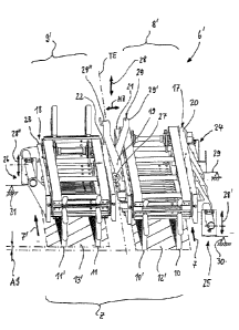
In Fig. 1, a root crop harvester in the form of a potato harvesting machine 1
is
illustrated - by a side view - in a schematic illustration. Such potato
harvesting
machines 1 comprise a leading lifting device 2 from where a mixture G (Fig. 2)
comprising the crop E as well as clods, haulm and similar admixtures B is
movable into the region of downstream screening belts 3 or similar transport
elements. In this context, the mixture G supplied to one of the feed belts 4
in
accordance with a feed direction 5 reaches a sorting zone Z (Fig. 2, hidden).
In
this sorting zone Z, the crop E can be sorted out by means of a separating
device 6 arranged above the feed belt 4 and acting transverse to its feed
direction 5 on the mixture G.
The known embodiments of these component groups of separating device 6 and
feed belt 4 (DE 10 2007 034 446 Al) comprise in this context two stripper
belts 8
and 9 circulating in the same direction in a respective stripping direction 7,
7'
(Fig. 3) which by means of respective stripping elements 10, 10' as well as
11,
11 engage the crop E. Accordingly, two stripping planes 12 and 13 (Fig. 3) are
defined which in feed direction 5 are arranged adjacent to each other or one
behind the other. From here, the crop E which has been substantially freed
from
clods B is supplied to a downstream sorting belt 14 (Fig. 2). In this context,
as
stripper elements 10, 10' as well as 11, 11', selectively fingers belts (Fig.
9) or
brush webs (not illustrated) can be used in order to make a pre-adjustment
regarding the ratio of admixtures B and crop E in the mixture G in accordance
with the harvesting conditions.
Respective admixtures B which remain as residue on the feed belt 4, in
particular in the form of rocks and clods, are supplied, preferably in a
guiding
direction 5' (Fig. 6) displaced relative to the stripping direction 7 by 90E,
to a
lateral discharge conveyor 15. The two stripper belts 8, 9 comprise in this
context
a common support structure T as a support device so that, based on a position
- 15 -
Date Recue/Date Received 2022-03-30
(Fig. 3) forming a working gap AS, a common adjustment is possible such that
in
lifting direction 16 a variation of the working gap AS is possible (Fig. 4).
Based on the embodiment illustrated in Fig. 2 to Fig. 4 of the prior art -
with
simultaneously displaceable and height-adjustable stripper belts 8, 9
(direction of
arrow 16, Fig. 4) - the concept according to the invention provides that the
separating device 6 now comprises a construction in which the two stripper
belts
8', 9' are individually adjustable (Fig. 5 to Fig. 8, schematic illustrations)
in the
region of at least one support device holding them, respectively.
The concept according to the invention with the individual adjustment of
component groups provides that the stripper elements 10, 10' and 11, 11' of
the
respective stripper belt 8', 9' by means of respective adjusting connectors
acting
individually in the direction of arrow 16' and 16'= are displaceable into
substantially variable Avertical@ spacings VA and VA= (Fig. 5) relative to the
feed
belt 4. Also, it is provided that the angular positions indicated generally by
WA
and WA= can be varied by corresponding individual adjustments of the stripper
belts 8', 9' (Fig. 6). In this way, it is apparent that the two stripper belts
8', 9'
relative to the feed belt 4 - in the region of the sorting zone C - can
comprise
positions that are each individually adjustable and continuously variable.
The stripper belts 8', 9' define, corresponding to their adjustment in the
region of
the sorting zone Z, a respective working gap AS with variable dimensions
and/or
contours (Fig. 5 to Fig. 8) so that the mixture G is exposed to different
sorting
loads. The latter are in particular adaptable to the field-specific harvesting
conditions.
Based on the illustrations according to Fig. 6 and Fig. 7, it is apparent that
the
respective stripper planes 12', 13' of the stripper belts 8', 9' in their
respective
transverse direction are adjustable to changeable tilting angles in accordance
with the arrows WA and WA=. The constructive configuration of the adjusting
connectors can be realized such that the stripper belts 8', 9' can be pivoted
in the
same direction clockwise or counterclockwise (Fig. 6, Fig. 7). Likewise, it is
- 16 -
Date Recue/Date Received 2022-03-30
conceivable to realize a system with opposite pivoting direction (similar:
Fig. 8,
pivoting according to arrow WA=>, stroke 16=>=).
Based on the illustration according to Fig. 5, it is apparent that the
stripper
planes 12, 13 of the two stripper belts 8, 9' each individually are adjusted
in
their parallel spacing relative to the correlated feed belt 4 (spacings VA and
VA=). A combined tilting and lifting adjustment is shown in Fig. 8 wherein the
stripper belt 8' is displaced in lifting direction 16'=> and the stripper belt
9' is
pivoted in a tilting direction WA=> such that the previously enlarged working
gap
is made smaller by the outwardly positioned stripper elements 11'. This also
makes clear that the contour of the working gap AS provided for the mixture G
has different structures, respectively. A stepped configuration is shown in
Fig. 5;
tapering and widening embodiments are shown in Fig. 6; an Ainner@ shaped arc
is provided in the embodiment according to Fig. 7; and also the variant with
continuously increasing constriction according to Fig. 8 is conceivable with
variable dimensions of the working gap AS.
In the illustrated embodiments, it is respectively provided that the two
stripper
belts 8', 9' comprise each two rows of circulating stripper elements 10, 10'
and
11, 11', wherein these two rows in the respective adjustments of the working
gap
AS (Fig. 5 to Fig. 8) are to be displaced together, respectively. Conceivable
is
also an expansion of the concept according to the invention wherein also
variable embodiments of length and number of stripper elements and/or their
respective individual adjustment is conceivable (not illustrated).
When looking jointly at the illustrations according to Fig. 6 to Fig. 8, it is
apparent
that the two stripper belts 8', 9' for their simultaneous adjustment comprise
a
central support connection 19. In this context, the two support devices 17, 18
are
connected in the region of a dividing plane TE.
When looking jointly at the schematic illustrations according to Fig. 5 to
Fig. 8
with the constructive detail embodiments according to Fig. 9 to Fig. 11, it is
apparent that the two stripper belts 8', 9' each comprise as a support device
17,
- 17 -
Date Recue/Date Received 2022-03-30
18 a support frame which is provided with lateral plates 20, 21 and 22, 23. It
is
provided in this context that the neighboring lateral plates 21 and 22 form at
least
said one support connection 19. This support construction can be completed in
that at least one support connection with adjusting device 24, 25, 26 is
provided
at the two outer lateral plates 20 and 23, respectively.
In this way, a construction is provided in which the two stripper belts 8', 9'
in the
region of the central support connection 19 can be guided for each adjusting
movement and, at the same time, the afore described individual adjustments of
the stripper belts 8', 9' by means of the outer adjusting devices 24, 25, 26
can be
controlled selectively.
Based on the illustrations, it is apparent that the stripper belts 8', 9' in
the region
of the central support connection 19 can be interacting in particular by means
of
a pivot joint 27. This pivot joint - illustrated in the embodiment according
to the
schematic illustration Fig. 7 - can be displaced in a lifting direction 28 so
that the
simultaneous displacement illustrated in Fig. 7 of the two stripper belts 8',
9' in
pivot direction WA, WA= is achieved. For a restoring movement into the start
position (Fig. 10) - preferably extending parallel to the feed belt 4- a
mechanism
29, not illustrated in detail, for example, with a restoring spring, can be
provided
in the region of the pivot joint 27. Independent of the adjusting devices
provided
for the lifting movement 28, a substantially automatic restoring movement of
the
component groups into the start position is also conceivable in this way.
The lifting movement 28 is controlled in this context in the region of the
mechanism 29 whose arms 29' and 29'=, connected in a cross shape in the pivot
joint 27, are connectable to an adjusting component group BZ (Fig. 10). By a
pulling movement MZ, the movement component according to the lifting direction
28 is triggered. At the same time, a height adjustment according to arrow 28',
28'= (Fig. 7) in the region of the stationary support connectors 30, 31 can be
controlled so that the tilted positions of the two stripper belts 8', 9',
indicated by
the pivot directions WA, WA=, can be reached continuously.
- 18 -
Date Recue/Date Received 2022-03-30
In Fig. 9, a conceivable embodiment of the system according to the invention
is
illustrated with constructive details. In this context, it becomes apparent
that the
separating device 6' can be preferably provided with only three support
connections 29, 30, 31 in the region of the adjusting devices 24, 25, 26. In
this
way, an advantageous three-point support relative to the machine frame, not
shown in detail, of the harvesting machine 1 is provided. It comprises a
sufficiently torsion-stiff system in the sorting zone 7 so that a quick
displacement
of the sorting components is possible with comparatively few adjusting
component groups.
In Fig. 10 and Fig. 11, the system is illustrated similar to Fig. 9 wherein
here the
Acrossing position@ of feed belt 4 and stripper planes 12', 13' becomes
apparent.
In Fig. 11 a slanted plan view of the components shows that the separating
device 6 is oriented in a position (angle 32) slanted at an acute angle above
the
feed belt 4. Conceivable are also further variants, not illustrated in detail,
of this
mounted position of the separating device 6'.
A further solution according to the invention in accordance with Fig. 12
discloses
stripper belts 8' and 9' whose stripper elements 10, 11 (as well as 10' and
11',
not illustrated) are shown only partly. The illustrated objects of the
embodiments
according to the invention, like those in the afore described Figs. 5 to 11
and
following Figs. 13 to 16, are in general part of a potato harvesting machine
generally shown in Fig. 1.
Above the sorting zone Z, the stripper belts 8' and 9' extend in the shown
illustration according to Fig. 12 initially parallel to the conveying plane F.
However, the two stripper belts 8' and 9' comprise toward their respective end
discharge sections AB angled relative to the parallel extension of the belt.
In
these sections AB, the stripper belt 8' or stripper belt 9', after an initial
deflection,
is provided with a constant incline such that the stripper elements 10, 11 in
operation gradually and continuously are removed from the goods to be sorted
without this leading, due to the deflection, to too strong an impulse in the
direction of the side of the downstream sorting belt 14.
- 19 -
Date Recue/Date Received 2022-03-30
The incline of the stripper belts in the respective discharge section results
from
the illustrated angle W between the contour of the pulling element of the
stripper
belt 8' 0r9' and the stripper planes 12', 13' that presently are coinciding
with the
conveying plane 7. The angle W is smaller than 55E.
Similar to the preceding embodiments according to the invention, the
embodiment according to Fig. 12 comprises stationary support connectors 30
which, for example, are attached to a machine frame, not illustrated. At these
support elements, guide rods 42 moveable in the direction of the double arrow
41 are supported by means of which the stripper belts 8' and 9' can be
displaced
in accordance with the directions 41, indicated by the double arrow.
The stripper belts 8' and 9' are of different length, wherein the stripper
belt 8 with
correlated frame elements is arranged displaced parallel relative to the
stripper
belt 9 in such a way that the respective stripper elements, in case of a non-
rectangular arrangement of the support device or of the stripper belts
relative to
the feed belt, the stripper elements 10, 10', 11, and 11' in operation of the
potato
harvesting machine according to the invention both begin to act approximately
at
the level of the rim of the feed belt 4, respectively (Fig. 13). Moreover, in
combination with Fig. 12, it can be seen that the spacing of stripper elements
10,
and 11, 11' that are positioned one behind the other in the stripping
direction
7 or 7' is different wherein, viewed in the feed direction 5, the spacings of
the
leading stripper elements 10 is greater than that of the stripper elements 11.
Moreover, viewed in the same direction 5, the spacings and heights of the
stripper elements 10, 10', 11, 11' across the conveying plane are designed
such,
be it due to the length of the different fingers or due to the adjustability
and
slanted position of the respective stripper belts 7, 7', that the
fractionation
illustrated on the sorting belt 14 results. Arrows P1, P2, P3, and P4 show the
corresponding sorting curves based on in particular different sorting
parameters,
comprising angular position WR and WR=, length and spacing of the stripper
elements 10, 10', 11, 11' as well as positioning of the stripper belts 8' and
9'
relative to their longitudinal direction.
- 20 -
Date Recue/Date Received 2022-03-30
For a particularly good sorting of the mixture G, the deflection of the root
crop is
carried out at an angle > 90 between the directions 5 and 7 or 7' so that the
sorting zone Z can be extended. The sorting zone Z assumes a correspondingly
large surface area wherein it may be advantageous to provide an additional
intermediate conveyor belt 43 which can be embodied as a conventional
hedgehog web or rubber knob web and comprises an analog conveying speed
and direction relative to the feed belt.
For the purpose of further adaptation to different sorting parameters, the
entire
support device that carries the stripper belts 8' and 9' can be designed in a
further embodiment, not illustrated, so as to be pivotable about a vertical
axis
which is projecting from the illustration plane of Fig. 13. In this case, the
stationary support connector 30 would be preferably secured on a pivot frame.
A
length adjusting device 44 that is secured on the adjusting device 24, which
is
also at least partially stationarily secured, can effect a displacement of the
stripper belts with correlated support pipes 45 and 46 of the support device.
In
this way, the stripper belts 8' and 9' can be moved from the working position
illustrated in Fig. 13 into the further working position illustrated in Fig.
14 in order
to take into account different harvesting conditions, changing size class
distributions, and other sorting parameters. Moreover, the root crop harvester
which in the working position according to Fig. 13 possibly surpasses a
permissible road width, can be reduced again to a permissible road width by
positioning the separating device in the position illustrated in Fig. 14.
The intermediate conveyor belt 43 as well as the feed belt 4 and the sorting
belt
14 have parallel conveying directions relative to each other. Moreover, viewed
in
a side view according to Fig. 15 as well as Fig. 12, it can be seen that these
three belts form a common conveying plane F without drop stage. Even though
in operation the fractions are transferred from the sorting belt 14 onto a
somewhat lower extending picking table belt 46 by means of a transfer roller
47,
the crop is however not conveyed by falling in this context but at a slant
conveyed away so that also a drop stage-free transport of the crop to the
picking
table is realized. Alternatively, the sorting belt 14 could also be embodied
to be
longer all the way to the picking table, not illustrated.
-21 -
Date Recue/Date Received 2022-03-30
A lateral discharge conveyor 15 is provided for discharging admixtures B of
the
mixture G that are feedable in a targeted fashion by transverse conveying
rollers
48.
These rollers 48 are also illustrated in Fig. 16 in a view in direction of the
stripping directions 7 or 7' similar to Figs. 5 to 7. While the stripper belt
8' in the
viewing direction comprises only two adjacently extending rows of stripper
elements 11 to 11', the leading stripper belt 9' in feed direction 5 is
provided first
with a double row D of closely adjacently positioned stripper elements 10,
which
however in longitudinal direction of the conveying belt are displaced relative
to
each other, as well as a further row of stripper elements 10'. The stripper
elements 10 of a double row D have moreover a different length in order to be
able to act also at different levels optimally on the incoming admixtures B
and
crop components of the mixture G.
Regardless of the illustrations in Figs. 12 to 16 in which the stripper planes
and
the conveying plane F are parallel to each other, by the already explained
arms
29 and 29' that are connected to each other by means of the pivot joint 27,
relative positions of the stripper belt 8' and 9' can be adjusted in order to
react
during operation, without changing stripper elements or individual stripper
belts,
to varying mixtures and sorting conditions. For example, in case of greatly
varying sizes, the stripper belt 9' that is first in feed direction 5 can be
angled
somewhat in order to enlarge in operation the spacing of the stripper elements
relative to the conveying plane compared to the downstream stripper
elements.
Due to the off-center arrangement of the two stripper elements 10 of the
double
row, it is in particular possible to generate an impulse dissolving
accumulations
present on the feed belt 4.
- 22 -
Date Recue/Date Received 2022-03-30