Note: Descriptions are shown in the official language in which they were submitted.
WO 2021/071652
PCT/US2020/051385
ELECTRIC MOTOR AND BLADE ASSEMBLY FOR A LAWN MOWER
FIELD OF THE INVENTION
[0001j The present invention relates to an electric motor
and blade assembly for a lawn
mower.
BACKGROUND
1000211 A spindle assembly for a lawn mower often includes
a spindle shaft having upper and
lower bearings to maintain a spindle shaft in alignment A blade is mounted to
a bottom end of
the spindle shaft and rotates with the spindle shaft to cut grass. The lower
bearing often wears
out before the upper bearing and needs to be repaired or replaced
(collectively "serviced").
Servicing the lower bearing often leads to tilting or other movement of the
spindle shaft from its
operational position. Because traditional spindle assemblies are connected to
the prime mover
through belts or other types of transmission, there is often enough "give" in
the system to
accommodate the spindle shaft tilting associated with servicing the lower
bearing without any
concern about damaging other components of the mower.
[0003] During operation of a lawn mower, a cutting blade
driven by a prime mover (e.g., an
internal combustion engine) may experience a blade impact event (e.g., the
cutting blade may
strike a natural or man-made object such as a rock, tree root, stake, etc.).
The blade impact event
results in an impact force on the cutting blade. In known lawn mowers, rotary
power is supplied
to the cutting blade from the prime mover through a force transmission element
such as a belt. In
such known lawn mowers, the force transmission element may absorb the impact
force on the
blade either through an elastic property of the force transmission element
(e.g., resilience of its
material such as rubber) or through the force transmission slipping (e.g., a
belt slipping on a
sheave) or both.
SUMMARY
[0003] In one embodiment, the invention provides an
electric motor for a lawn mower
including a spindle housing having a bore with a spindle clearance opening. An
upper housing
coupled to an upper portion of the spindle housing. A stator positioned within
the upper housing.
A spindle shaft extending vertically through the bore of the spindle housing.
The spindle shaft
CA 03154251 2022-4-8
WO 2021/071652
PCT/US2020/051385
having an upper spindle shaft portion and a lower spindle shaft portion. A
rotor coupled to the
stator within the upper housing and coupled to the spindle shaft for rotation
of the spindle shaft.
An upper bearing supporting the upper spindle shaft portion in the rotor A
lower bearing
supporting the lower spindle shaft portion. A lower bearing carrier mounted to
the spindle
housing and supporting the lower bearing proximate to the spindle clearance
opening. A blade
adapter coupled to the lower spindle shaft portion_ A bearing debris guard
coupled to the spindle
housing aromid the lower bearing, the lower bearing carrier, and a portion of
the blade adapter to
protect the lower bearing from debris, A blade coupled to the blade adapter
with a blade
mounting fastener.
100041 in some embodiments, the invention further
comprises a washer having outer edges
embedded within a lower portion of the debris guard. In some embodiments, the
washer is
formed of a metallic material with the central exposed portion providing a
bearing surface in
frictional engagement the blade. In some embodiments, a bearing surface is
formed by the debris
guard or the Made adapter, wherein the blade is configured to slip relative to
the spindle shaft
and the bearing surface when a blade impact event occurs. In some embodiments,
the blade
adapter includes a stand-off portion that extends through the bearing debris
guard, wherein a gap
extends between the mounting fastener and the bearing surface. In some
embodiments, the
invention further comprises a biasing member positioned in the gap and
deflected by the blade
mounting fastener when the gap is narrowed, wherein the biasing member
generates a blade
coupling force on the blade. In some embodiments, the blade coupling force
generates a blade
coupling friction between the blade and the bearing surface to frictionally
couple the blade and
the spindle shaft for rotation together. In some embodiments, the blade slips
with respect to the
spindle shaft in response to the blade encountering a force resisting rotation
of the blade to an
extent that overcomes the blade coupling friction.
[00051 In another embodiment, the invention provides a
method of assembling and servicing
an electric motor having a spindle housing defining a bore with a spindle
clearance opening and
an upper housing coupled to an upper portion of the spindle housing. The
method includes
positioning a stator in the upper housing, Coupling a rotor to the stator
within the upper housing.
Positioning a spindle shaft within the bore. The spindle shaft extending
vertically through the
bore of the spindle housing. The spindle shaft having an upper spindle shaft
portion and a lower
CA 03154251 2022-4-8
WO 2021/071652
PCT/US2020/051385
spindle shaft portion. Supporting the upper spindle shaft portion in the rotor
with an upper
bearing. Supporting the lower spindle shaft portion with a lower bearing.
Supporting the lower
bearing proximate to the spindle clearance opening with a lower bearing
carrier mounted to the
spindle housing. Coupling a blade adapter to the lower spindle shaft portion_
Coupling a bearing
debris guard to the spindle housing around the lower bearing, the lower
bearing carrier, and a
portion of the blade adapter to protect the lower bearing from debris.
Coupling a blade to the
blade adapter with a blade mounting fastener.
100061
In some embodiments, the
invention further comprises restricting the motion of the
spindle shaft with the spindle clearance opening when the lower bearing, the
lower bearing
carrier, the blade adapter, the bearing debris guard, and the blade are
removed from the electric
motor. In some embodiments, the invention further comprises replacing the
lower bearing with a
replacement lower bearing and coupling the replacement lower bearing, the
lower bearing
carrier, the blade adapter, the bearing debris guard, and the blade to the
electric motor. In some
embodiments, the invention further comprises uncoupling the blade mounting
fastener to remove
the blade from the blade adapter. In some embodiments, the invention further
comprises
uncoupling the bearing debris guard from the spindle housing to allow access
to the lower
bearing, the lower bearing carrier, and the blade adapter. In some
embodiments, the invention
further comprises uncoupling the blade adapter from the lower spindle shaft
portion. In some
embodiments, the invention further comprises unmounting the lower bearing
carrier from the
spindle housing to remove the lower bearing carrier and the lower bearing from
the electric
motor. In some embodiments, the invention further comprises restricting the
motion of the
spindle shaft with the spindle clearance opening. In some embodiments, the
invention further
comprises providing a replacement lower bearing in the lower bearing carrier.
In some
embodiments, the invention further comprises mounting the lower bearing
carrier to the spindle
housing so the replacement lower bearing supports the lower spindle shaft
portion_ In some
embodiments, the invention further comprises coupling the blade adapter,
debris guard, and the
blade to the electric motor.
[00071
In another embodiment, the
invention provides an electric motor for a lawn mower
including a spindle housing having a bore with a spindle clearance opening. An
upper housing
coupled to an upper portion of the spindle housing. A stator positioned within
the upper housing.
3
CA 03154251 2022-4-8
WO 2021/071652
PCT/US2020/051385
A spindle shaft extending vertically through the bore of the spindle housing.
The spindle shaft
having an upper spindle shaft portion and a lower spindle shaft portion. A
rotor coupled to the
stator within the upper housing and coupled to the spindle shaft for rotation
of the spindle shaft
An upper bearing supporting the upper spindle shaft portion in the rotor A
lower bearing
supporting the lower spindle shaft portion. A lower bearing carrier mounted to
the spindle
housing and supporting the lower bearing proximate to the spindle clearance
opening. A blade
adapter coupled to the lower spindle shaft portion. A bearing debris guard
coupled to the spindle
housing around the lower bearing, the lower bearing carrier, and a portion of
the blade adapter to
protect the tower bearing from debris_ A blade coupled to the blade adapter
with a blade
mounting fastener. The blade, the bearing debris guard, the blade adapter, the
lower bearing
carrier, and the lower bearing are removable from the electric motor. The
spindle clearance
opening limits the radial movement of the lower portion of the spindle shaft
when the blade, the
bearing debris guard, the blade adapter, the lower bearing carrier, and the
lower bearing are
removed from the electric motor.
100081 In another embodiment, the invention provides an
assembly for mounting a blade to a
spindle. The assembly includes a first bearing surface on one side of the
blade and frictionally
engaging the blade. The first bearing surface rigidly coupled for rotation
with the spindle. A
second bearing surface on an opposite side of the blade. A biasing mechanism
in a gap between
the second bearing surface and the blade. A fastener operable to move the
second bearing surface
toward the blade to narrow the gap and deflect the biasing mechanism. A gap
setting component
preventing the fastener from narrowing the gap beyond a preferred gap size.
The biasing
mechanism generates a blade coupling force in response to the gap achieving
the preferred gap
size. The blade coupling force generates a blade coupling friction between the
blade and the first
bearing surface to frictionally couple the blade and the spindle for rotation
together. The blade
slips with respect to the spindle in response to the blade encountering a
force resisting rotation of
the blade to an extent that overcomes the blade coupling friction.
100091 Other aspects of the invention will become apparent
by consideration of the detailed
description and accompanying drawings.
BRIEF DESCRIPTION OF THE DRAWINGS
4
CA 03154251 2022-4-8
WO 2021/071652
PCT/US2020/051385
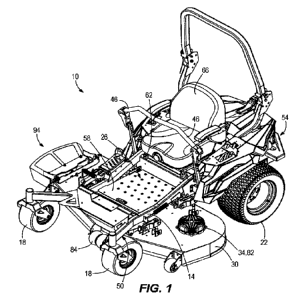
[00101 FIG. 1 is a perspective view of an electric zero
turn lawn mower according to the
present invention.
[001.11 FIG. 2 is another perspective view of the lawn
mower of FIG. 1.
[00121 FIG. 3 is a bottom perspective view of the lawn
mower.
100131 FIG. 4 is a perspective view of a battery
compaitment of the lawn mower.
[00141 FIG. 5 is a perspective view of a cutting deck of
the lawn mower.
100151 FIG. 6 is a perspective view of a spindle assembly
of the lawn mower.
100161 FIG. 7 is a cross-sectional side view of the
spindle assembly.
100171 FIG. 8 is an exploded perspective view of the
spindle assembly.
[00181 FIG. 9A is a cross-sectional side view of the
spindle assembly with a blade assembly,
a bearing debris guard, a lower bearing carrier, and a lower bearing removed.
[00191 FIG. 9B is an isolated cross-sectional side view
illustrating a spindle shaft of the
spindle assembly extending through a bore within a spindle housing of the
spindle assembly.
[00201 FIG. 9C is the isolated cross-sectional side view
of FIG. 9B with the spindle shaft
transparently illustrated.
DETAILED DESCRIPTION
[00211 Before any embodiments of the invention are
explained in detail, it is to be
understood that the invention is not limited in its application to the details
of construction and the
arrangement of components set forth in the following description or
illustrated in the following
drawings. The invention is capable of other embodiments and of being practiced
or of being
carried out in various ways. As used herein, terms relating to position (e.g.,
front, rear, left,
right, etc.) are relative to an operator situated on a utility vehicle during
normal operation of the
utility vehicle.
CA 03154251 2022-4-8
WO 2021/071652
PCT/US2020/051385
[0022} One problem addressed with the present invention
arises from the nature of a cutting
deck spindle assembly that includes a dedicated, direct-drive electric deck
motor. Such an
assembly includes, among other elements as will be explained below, the deck
spindle, the
electric deck motor, an upper spindle bearing, and a lower spindle bearing.
Such assembly gives
rise to unique problems relating to the direct-drive nature of the assembly
and the sensitivity of
the electrical components (e.g., the rotor and stator) of the electric deck
motor.
[0023J Due to the direct-drive nature of the assembly
(i.e., the electric deck motor is directly
coupled to the spindle), there is no force transmission element such as a belt
to absorb the impact
force on the cutting blade during a blade impact event. The impact force
follows a relatively
rigid load path from the blade, through the spindle, and to the electric deck
motor with very little
or no "give" in the load path. Therefore, the components of such cutting deck
spindle assembly
may be damaged from a single impact force or repeated impact forces_
[00241 Another problem addressed with the present
invention is the difficulty of replacing
the lower spindle bearing of a deck spindle assembly that includes a
dedicated, direct-drive
electric deck motor. The lower bearing of a deck spindle assembly tends to
wear out faster than
the rest of the assembly. As a result, the lower bearing can be serviced from
time-to-time to
extend the life of the overall spindle assembly. This poses no significant
problems for a known
spindle assembly that is driven though a force transmission element. But
because of the direct-
drive nature of a deck spindle assembly that includes a dedicated, direct-
drive electric deck
motor, any significant off-axis displacement (e.g., tipping or radial
movement) of the spindle
while the lower bearing is being serviced could damage the sensitive
electrical components of
the electric deck motor (e.g., the stator or rotor). Consequently, great care
needs to be taken
when replacing the lower spindle bearing to limit off-axis displacement of the
spindle within an
acceptable range that will avoid damage to the electric deck motor.
[0025j Figs. 1-4 illustrate a lawn mower 10. The lawn
mower 10 may be, for example, an
electric lawn mower, an internal combustion lawn mower, or a hybrid lawn
mower. The
illustrated lawn mower 10 includes a frame 14, a plurality of rotatable wheels
or ground-
engaging elements 18, 22 coupled to the frame 14, an operator platform 26
supported by the
frame 14, a cutting deck 30 coupled to the frame 14. The lawn mower 10
includes a prime
6
CA 03154251 2022-4-8
WO 2021/071652
PCT/US2020/051385
mover (e.g., an internal combustion engine, one or more electric motors,
etc.). In the illustrated
embodiment, the prime mover includes a plurality of prime movers in the form
of dedicated
drive motors 42 (Fig. 3) and deck motors 34.
[00261 The drive motors 42 are supported by the frame 14,
with each coupled to one of the
rear ground-engaging elements 22 to independently drive rotation of the
associated rear ground-
engaging element 22 at a selected speed and direction. In this regard, the
rear ground-engaging
elements 22 may also be referred to as the "drive wheels_" In the illustrated
embodiment, the
front ground-engaging elements 18 are passive caster wheels. In other
embodiments, similar
drive motors may also or alternatively be coupled to the front ground-engaging
elements 18 for
the same purpose as the drive motors 42. The deck motors 34 are mounted to the
cutting deck 30
and are part of the spindle assemblies as will be discussed in more detail
below. Because of the
direct connection between the deck motors 34 and the spindle assemblies, the
deck motors 34
can be referred to as direct drive motors. The drive and deck motors 42, 34
are powered by a
power source (Fig. 4) which, in the illustrated embodiment, is a bank
(plurality) of batteries 38
(also called battery packs). In some embodiments, a single battery may be used
as the power
source. The batteries 38 are electrically coupled to the drive motors 42 and
deck motors 34 to
provide enough power for their operation.
100271 With reference to Figs. 1 and 2, the illustrated
lawn mower 10 includes operator
controls 46. The operator controls 46 are coupled to the frame 14 adjacent the
operator platform
26. The operator controls 46 are operable to control the lawn mower 10. For
example, the
operator controls 46 can be used to control the drive motors 42 to drive a
desired speed and
direction of rotation of the rear ground-engaging elements 22 to move and/or
turn the lawn
mower 10. In the illustrated embodiment, the operator controls 46 include two
handles used for
a. zero-turn radius (ZTR) lawn mower. In other embodiments, the operator
controls 46 may
include other suitable actuators, such as a steering wheel, joystick(s), and
the like. In some
embodiments, a control panel (e.g., a display, ignition, etc.) may be
supported by the frame 14 to
selectively control the activation and operation of the deck motors 34 and the
drive motors 42.
[00281 The frame 14 includes a first or front portion 50
(extending to the center of the frame
14) and a second or rear portion 54 (meeting the front portion 50 at the
center of the frame 14)
'7
CA 03154251 2022-4-8
WO 2021/071652
PCT/US2020/051385
opposite the front portion 50. The frame 14 defines the basic body structure
or chassis of the
lawn mower 10 and supports the other components of the lawn mower 10. The
cutting deck 30 is
supported underneath the frame 14 mainly in the front portion 50 in the
illustrated embodiment,
but in other embodiments might be moved rearward to the center or even fully
to the rear portion
54, for example. The batteries 38 are illustrated as being supported in the
rear portion 54, but in
other embodiments may be supported on the front portion 50 or in the center
between the front
and rear portions 50, 54 of the frame 14.
100291 The ground-engaging elements 18, 22 are movably
(e.g., rotatably) coupled to the
frame 14. The illustrated ground-engaging elements 18, 22 include two first
ground-engaging
elements 18 coupled to the front portion 50 of the frame 14, and two second
ground-engaging
elements 22 coupled to the rear portion 54 of the frame 14. In the illustrated
embodiment, the
ground-engaging elements 18, 22 are wheels but in other embodiments could be
tracks for
example. The first ground-engaging elements 18 are idle wheels that are not
driven by the prime
mover, while the second ground-engaging elements 22 are driven wheels that are
operatively
coupled to the prime mover. In other embodiments, the first ground-engaging
elements 18 may
also or alternatively be driven wheels that are operatively coupled to the
prime mover.
[00301 The operator platform 26 is supported by the frame
14 and located in the middle of
the frame 14 (partially on the front portion 50 and partially on the rear
portion 54). The
illustrated operator platform 26 includes a first or lower section 58 and a
second or upper section
62. The lower section 58 is located forward of the upper section 62 and
configured to support a
user's feet. The upper section 62 is located rearward of the lower section 58
and supports a seat
66. The seat 66 allows a user to sit during operation of the lawn mower 10 and
access the
operator controls 46. In some embodiments, the operator platform 26 may only
include the
lower section 58 such that the lawn mower 10 is a standing vehicle. In such
configurations, the
operator platform for the standing using may be at the rear of the mower. In
further
embodiments, the operator platform 26 may have other configurations. An
operator zone is
defined as the seat 66 and all controls and other elements of the lawn mower
10 that can be
reached by the user while seated 66, such as the operator controls 46, a
portion of the operator
platform 26 that support the user's feet, and any foot-actuated brakes or
controls in reach of the
user while the user is in the seat 66.
8
CA 03154251 2022-4-8
WO 2021/071652
PCT/US2020/051385
[00311 With reference to Fig 4, the batteries 38 are
positioned in a battery compartment 70
supported by the frame 14. A lid 74 is pivotally coupled to the battery
compartment 70. The lid
74 includes a latch 76 that selectively secures the lid 74 to the batten'
compartment 70 in a
closed condition in which the batteries 38 are fully enclosed within the
battery compartment 70
and covered by the lid 74. The batteries 38 are coupled to a bus bar (not
shown) that operably
(i_e., electrically) couples the batteries 38 to the deck motor(s) 34 and the
drive motor(s) 42
through a vehicle control module 78 (illustrated schematically). The mower 10
may include one
or more charging ports 80 (illustrated schematically) to charge the batteries
38, while the
batteries 38 are positioned within the battery compartment 70. Additionally,
the batteries 38 may
be removed from the battery compartment 70, when the lid 74 is in an open
condition (e.g., as
shown in Fig. 4) to charge the batteries 38 on an external charger. In other
embodiments, the
batteries 38 may be positioned in an alternative position within the mower 10.
Additionally, or
alternatively, an internal combustion engine may be used as the prime mover of
the lawn mower
and the batteries 38 may be used only for the deck motors 34.
100321 With reference to Figs. 3 and 5, the cutting deck
30 includes one or more ground-
engaging elements 84 (e.g., anti-scalping rollers) that support the cutting
deck 30 on the ground.
A plurality (three in the illustrated embodiment) of deck spindle assemblies
82 are mounted to
the cutting deck 30. In the illustrated embodiment, the cutting deck 30
includes three spindle
assemblies 82. In other embodiments, the cutting deck 30 may include fewer
spindle assemblies
82 (e.g., one or two) or more spindle assemblies 82 (e.g., three, four, etc.).
Each spindle
assembly 82 includes a blade assembly 86 (Fig, 3) having a blade 90 that is
under the cutting
deck 30 to cut grass under the cutting deck 30. In some embodiments, the blade
assembly 86
may include only the blade 90 and a blade mounting fastening device to secure
the blade 90 to
the spindle assembly 82. In other embodiments, the blade assembly 86 may
include additional
components as described below. In the illustrated embodiment, the cutting deck
30 includes a
side discharge opening 94 to discharge mown grass. In other embodiments, the
mower 10 may
include a rear discharge opening, a collection bag, etc. While lawn mower 10
is described above
as an electric zero turn lawn mower, it should be appreciated that the spindle
assembly 82 and
the blade assembly 86 as described below may be used with any utility device
that is operable to
cut grass. Additionally, it should be appreciated that the blade assembly 86
may be used with
other types of cutting deck (e.g., belt drive, etc.).
9
CA 03154251 2022-4-8
WO 2021/071652
PCT/US2020/051385
[00331 Figs. 6-9 illustrate one of the spindle assemblies
82. The spindle assembly 82
includes a spindle housing 98, an upper housing 102 coupled to an upper
portion of the spindle
housing 98, a vertical spindle shaft 114, an upper bearing 150, and a lower
bearing assembly 100
(Fig. 8). The blade assembly 86 is coupled to the spindle shaft 114. The lower
bearing assembly
100 includes a debris guard 106, a lower bearing 154, a lower bearing carrier
158, and lower
bearing mounting fasteners 170, and a blade adapter 174.
[00341 With reference to Fig. 7, a lower portion of the
spindle housing 98 includes a bore
110 and clearance opening 118 through which the vertical spindle shaft 114
extends_ The spindle
shaft 114 includes an upper spindle shaft portion 122 and a lower spindle
shaft portion 126. The
upper spindle shaft portion 122 is positioned within the upper housing 102 and
the lower spindle
shaft portion 126 extends through the clearance opening 118. The spindle shaft
114 defines a
spindle shaft axis 130 extending longitudinally and centrally through the
spindle shaft 114. In the
illustrated embodiment, the lower spindle shaft portion 126 includes a tapered
portion 134. In
other embodiments, the lower spindle shaft portion 126 may have a uniform
diameter. The lower
spindle shaft portion 126 includes a downward-opening threaded bore 126a and a
groove 126b
for an o-ring 131
[00351 The upper housing 102 forms an internal cavity 138
to house the motor 34 which
comprises a stator 142 and a rotor 146. The rotor 146 and stator 142 are
coupled in the sense that
the rotor 146 is sufficiently close to or proximate the stator 142 so that the
rotor 146 rotates with
respect to the stator 142 when the stator 142 is energized. For example, the
rotor 146 may
include a plurality of permanent magnets. The stator 142 includes
electromagnets (e.g., electric
coils) that form an electromagnetic field when a three-phase current is
applied to the
electromagnets. As a result, the permanent magnets of the rotor 146 interact
with the magnetic
field of the stator 142 to cause rotation of the rotor 146 relative the stator
142. In the illustrated
embodiment, the rotor 146 is coupled by way of a rotor fastener 144 to the
upper spindle shaft
portion 122 such that the rotor 146 and spindle shaft 114 rotate together
relative to the stator 142.
The stator remains stationary within or with respect to the upper housing 102.
The stator 142 and
rotor 146 are assembled in a precise way (with the upper bearing 150 as will
be described below)
for operation of the motor 34. As a result, excessive off-axis movement of the
spindle shaft 114
relative to the operating position of the spindle shaft axis 130 or an
excessive peak torque on the
CA 03154251 2022-4-8
WO 2021/071652
PCT/US2020/051385
stator 142 or rotor 146 may damage the motor 34 in the sense of misaligning
the stator 142 and
rotor 146.
100361 The upper bearing 150 is positioned between the
upper spindle shaft portion 122 and
the stator 142 to support the upper spindle shaft portion 122 in the stator
142 for rotation with
respect to the stator 142. A first part of the upper bearing 150 is fixed for
rotation with the upper
spindle shaft portion 122 and a second part of the upper bearing 150 is fixed
with respect to the
stator 142_ The upper bearing 150 permits relative rotation between the first
and second parts
about the spindle shaft axis 130.
[00371 The lower bearing 154 includes an inner race that
supports the lower spindle shaft
portion 126. The o-ring 135 creates a seal between the inner race and the
lower spindle shaft
portion 126_ The outer race of the lower bearing 154 is fixed with respect to
the lower bearing
carrier 158 and the lower bearing carrier 158 is in turn rigidly mounted to
the bottom of the
spindle housing 98. In the illustrated embodiment, the lower bearing carrier
158 includes a
bearing support cavity 162 and a plurality of mounting apertures 166 (through
holes) through
which the lower bearing mounting fasteners 170 extend. The lower bearing
mounting fasteners
170 pass through the mounting apertures 166 and thread into threaded bores 168
in a lower
portion of the spindle housing 98. As a result, the lower bearing carrier 158
is fixed with respect
to the spindle housing 98 and the outer race of the lower bearing 154 abuts
against the bottom of
the spindle housing 98. Owing to a shallow recess in the bottom of the spindle
housing 98, the
inner race of the lower bearing 154 rotates freely (with the spindle shaft
114) with respect to the
lower bearing carrier 158 and spindle housing 98.
100381 The lower bearing carrier 158 may be removed from
the spindle housing 98 by
unthreading the lower bearing mounting fasteners 170 from the threaded bores
168 when the
lower bearing 154 needs to be repaired or replaced (collectively "serviced").
In other
embodiments, the lower bearing carrier 158 may be mounted to the spindle
housing 98 in any
fashion that rigidly fixes the lower bearing carrier 158 to the spindle
housing 98 but also allows
the lower bearing carrier 158 to be removed from the spindle housing 98 for
service. In addition,
there is a close fit (pilot) between the lower bearing carrier 158 (female)
and the spindle housing
11
CA 03154251 2022-4-8
WO 2021/071652
PCT/US2020/051385
98 (male). This provides for a repeatably precise alignment between the lower
bearing 154 and
the upper bearing 150 on the spindle shaft axis 130 when the lower bearing 154
is serviced.
[00391 The blade adapter 174 is coupled to the lower
spindle shaft portion 126 adjacent the
lower bearing carrier 158. A reduced diameter upper portion of the blade
adapter 174 may extend
up through the bottom of the lower bearing carrier 158 and abut the bottom of
the inner race of
the lower bearing 154. In the illustrated embodiment, the blade adapter 174
may include a central
aperture 178 having a tapered engaving portion that engages with the tapered
portion 134 of the
spindle shaft 114. In other embodiments, the central aperture 178 of the blade
adapter 174 may
be formed to have any geometry that allows the blade adapter 174 to
frictionally engage with the
lower spindle shaft portion 126 so that the blade adapter 174 and spindle
shaft 114 are coupled
for rotation together.
100401 The blade adapter 174 includes a reduced-diameter,
downward-extending stand-off
portion 186 and a downward-facing shoulder 187 radially surrounding the top of
the stand-off
portion 186 where the stand-off portion 186 meets the main body of the blade
adapter 174. The
stand-off portion 186 includes a clearance hole 186a aligned with the threaded
bore 126a in the
lower spindle shaft portion 126. Both the clearance hole 186a and the threaded
bore 126a are
centered on the spindle shaft axis 130 of the lower spindle shaft portion 126.
100411 The bearing debris guard 106 includes a washer 182
having outer edges embedded
within a lower portion of the debris guard 106. The washer 182 includes a
central hole through
which the stand-off portion 186 extends. The bearing debris guard 106 is
frictionally coupled to
the blade adapter 174 for rotation therewith, as will be described below, and
extends up around
the lower bearing 154 and the lower bearing carrier 158 to shield or protect
the lower bearing
154 from debris. The bearing debris guard 106 may be formed of a plastic
material, a metallic
material, etc. The washer 182 may be formed of a metallic material (e.g.,
steel, aluminum, etc.)
with the central exposed portion providing a bearing surface in frictional
engagement with the
central mounting portion of the blade 90 as will be described below.
[00421 The blade assembly 86 includes the blade 90, a
biasing member 190 (e.g., a Belleville
spring washer), and an engagement washer 192 (e.g., a flat washer), each
including a hole
centered in the spindle shaft axis 130. A blade mounting fastener 194 extends
through the
12
CA 03154251 2022-4-8
WO 2021/071652
PCT/US2020/051385
aligned holes in the engagement washer 192, biasing member 190, blade adapter
174 (clearance
hole 186a), and blade 90, and threads into the threaded bore 126a in the lower
spindle shaft
portion 126. The free lower end of the stand-off portion 186 extends through
the hole in the
biasing member 190 and abuts the engagement washer 192.
[0043) The blade mounting fastener 194 traps the blade
assembly 86 and washer 182 of the
bearing guard 106 against the shoulder 187 of the blade adapter 174 with an
axial force. A blade
mounting gap 188 is defined between the shoulder 187 and the head of the blade
mounting
fastener 194. The washer 182 of the bearing debris guard 106, the blade 90,
the biasing member
190, and the engagement washer 192 are captured in the blade mounting gap 188.
The axial force
of the blade mounting fastener 194 narrows or closes the blade mounting gap
188 by pulling the
lower spindle shaft portion 126 and engagement washer 192 toward each other as
the blade
mounting fastener 194 advances into the threaded bore 126a.
[00441 The blade mounting gap 188 narrows or closes until
the lower spindle shaft portion
126 is tightly pressed into the tapered portion of the central aperture 178 of
the blade adapter 174
and the stand-off portion 186 is brought into tight abutting engagement with
the engagement
washer 192 and head of the blade mounting fastener 194. As the blade mounting
gap 188
narrows, the biasing member 190 is deflected, which increases friction (due to
the resulting
normal force of the biasing member 190) between all elements captured in and
defining the gap
188 (ie., the blade adapter 174, the washer 182 of the debris guard 106, the
blade 90, the biasing
member 190, the engagement washer 192, and the blade mounting fastener 194).
Thus, the
spindle shaft 114, blade adapter 174, debris guard 106, blade 90, biasing
member 190,
engagement washer 192, and blade mounting fastener 194 are frictionally
coupled for rotation
together as a result of the biasing force arising in the biasing member 190 as
the blade mounting
gap 188 is narrowed or closed.
[0045) The blade assembly is not limited to the components
and construction illustrated and
described. Fundamentally, what is required is a first bearing surface (e.g.,
the blade adapter 174,
debris guard 106, washer 182, or any other surface that engages one side of
the blade 90 and is
coupled for rotation with the spindle shaft 114), a gap setting component
(e.g., the stand-off
portion 186 or other component), and a second bearing surface (e.g., the
biasing member 190 or
13
CA 03154251 2022-4-8
WO 2021/071652
PCT/US2020/051385
another component that engages an opposite side of the blade 90). The first
and second bearing
surfaces frictionally engage the opposite sides of the blade 90. The gap
setting component
dictates the blade mounting gap 188 when the assembly is tightened and
prevents the blade
mounting fastener 194 from narrowing the gap beyond a preferred gap size. The
biasing member
190 has an at-rest or undeflected thickness or height and is deflected to a
reduced height in
response to the blade mounting gap 188 being narrowed to the preferred gap
size In response to
being deflected, the biasing member 190 generates a normal force or other
force which can be
referred to as a blade coupling force_ The blade coupling force gives rise to
friction, which can
be called a blade coupling friction, between the blade and at least the first
bearing surface to
frictionally couple the blade and the spindle for rotation together.
[00461 When the blade impact event occurs (e.g., the blade
90 strikes a rock, a stake, etc), a
force resisting rotation of the blade 90 is received by the blade 90. If the
force resisting rotation
of the blade 90 overcomes the blade coupling friction, die blade 90 slips with
respect to the
spindle shaft 114. For example, the blade 90 may slip with respect to the
first bearing surface and
the second bearing surface, while the spindle shaft 114 and the blade adapter
174 continue to
rotate. Other components in the gap may rotate with the spindle shaft 114 and
blade adapter 174
or may stop rotating along with the blade 90. The biasing member 190 and blade
90 absorb a
large amount of the impact torque from the blade impact event, and the impact
torque received
by the spindle shaft 114 and the sensitive electrical components of the deck
motor 34 (e.g., the
stator 142 and the rotor 146) is limited.
[00471 During operation of the lawn mower, the lower
bearing 154 is typically the first
component of the deck motor 34 to wear out. As a result, the construction of
the deck motor 34
allows the lower bearing 154, the debris guard 106, the blade adapter 174, and
the blade
assembly 86 to be removed from the spindle assembly 82 and deck motor 34 to
service the lower
bearing 154. Such servicing can be accomplished in the field or in a shop
without having to
disassemble the enter spindle assembly 82 and specifically without having to
disengage the
spindle shaft 114 from the motor 34.
[00481 With reference to Fig. 9A-C, the clearance opening
118 defines a radial shaft
alignment structure 198 in the bottom end of the spindle housing 98. An
annular clearance gap
14
CA 03154251 2022-4-8
WO 2021/071652
PCT/US2020/051385
202 is defined between the spindle shaft 114 and the clearance opening 118. In
the illustrated
embodiment, the clearance gap 202 is in a range from ten-thousandths of an
inch to twenty-
thousandths of an inch. In other embodiments, the clearance gap 202 may be
greater than twenty-
thousandths of an inch or less than ten thousandths of an inch.
[0049) The bore 110, clearance opening 118, and spindle
shaft 114 are precisely formed so
that when the lower bearing 154 is supporting the spindle shaft 114 the
clearance gap 202 is
consistently maintained around the spindle shaft 114 and the spindle shaft 114
does not contact
the shaft alignment structure 198. Ideally, the spindle shaft 114 is centered
in the clearance
opening 118 and both the spindle shaft 114 and clearance opening 118 are
perfectly circular such
that the clearance gap 202 is a consistent annular space between the spindle
shaft 114 and
clearance opening 118. It is recognized that nothing is perfect but with
advanced machining
processes, high tolerances can be achieved_ As such, during operation of the
motor 34 and
spindle assembly 82, when the spindle shaft 114 is spinning about the spindle
shaft axis 130, the
spindle shaft 114 does not contact the bottom wall of the spindle housing 98
in which the
clearance opening 118 is formed (i.e., the shaft alignment structure 198).
100501 When servicing the lower bearing 154, the lower
bearing 154 is removed which
permits the spindle shaft 114 to tip or pivot within the spindle housing 98
about a point in the
upper spindle portion 122 that is supported in the upper bearing 150. As the
spindle shaft 114
tips in this fashion, the lower spindle shaft portion 126 may contact the
shaft alignment structure
198. In an ideal construction, the extent to which the spindle shaft 114 is
permitted to tip in any
direction when not supported by the lower bearing 154 is the width of the
clearance gap 202.
100511 As illustrated in Fig_ 913, the shaft alignment
structure 198 constrains or prevents the
spindle shaft 114 from tipping more than a predetermined angle 206 relative to
the operating
orientation (e.g., vertical) of the spindle shaft axis 130. Although radial
movement (i.e., purely
perpendicular to the ideal operating position of spindle shaft axis 130) of
the spindle shaft 114 is
unlikely due to the upper bearing 150 and lower bearing 154, such radial
movement is also
constrained by the shaft alignment structure 198. In the illustrated
embodiment, the spindle shaft
114 is restricted from pivoting more than approximately 0.25-0.30 degrees and
from moving
radially more than approximately twenty-thousandths of an inch. To maintain
desired tolerances,
CA 03154251 2022-4-8
WO 2021/071652
PCT/US2020/051385
the diameter of the clearance opening 118 should be selected based on factors
such as the
diameter of the spindle shaft 114 and distance between the upper bearing 150
and the clearance
opening 118.
[00521 Removal of the lower bearing assembly 100 (debris
guard 106, lower bearing 154,
lower bearing carrier 158, lower bearing mounting fasteners 170, and blade
adapter 174) for
service will now be discussed. First the blade mounting fastener 194 is
uncoupled (i.e.,
unthreaded) from the lower spindle shaft portion 126 so that the blade adapter
174, bearing
debris guard 106, and blade assembly 86 can be removed from the lower spindle
shaft portion
126. Then the lower bearing mounting fasteners 170 are unthreaded from the
spindle housing 98
so that the lower bearing 154 and lower bearing carrier 158 can also be
removed from the spindle
housing 98. This leaves the lower spindle shaft portion 126 exposed through
the bottom of the
spindle housing 98 and free-hanging or unsupported in the clearance
opening/18. The motion of
the spindle shaft 114 is restricted or constrained as noted above by the shaft
alignment structure
198. A replacement, rebuilt, or repaired lower bearing 154 (collectively, a
"replacement lower
bearing 154") is inserted into the lower bearing carrier 158. The lower
bearing carrier 158 is
mounted to the spindle housing 98 with the lower bearing mounting fasteners
170, so the
replacement lower bearing 154 supports the lower spindle shaft portion 126.
Then the blade
adapter 174, debris guard 106, and blade assembly 86 are positioned on the
lower spindle shaft
portion 126. Last, the blade mounting fastener 194 is threaded into the
threaded bore 126a in the
lower spindle shaft portion 126 and tightened until the lower spindle shaft
portion 126 is tightly
pressed into the tapered portion of the central aperture 178 of the blade
adapter 174 and the
stand-off portion 186 is brought into tight abutting engagement with the
engagement washer 192
and head of the blade mounting fastener 194.
[00531 Thus, the invention is to cover all modifications,
equivalents, and alternatives falling
within the spirit and scope of the invention as defined by the following
claims.
16
CA 03154251 2022-4-8