Note: Descriptions are shown in the official language in which they were submitted.
POWER CONTROL METHOD AND APPARATUS, AND SENDING METHOD
AND APPARATUS FOR UPLINK TRANSMISSION
TECHNICAL FIELD
The present application relates to the field of communication, for example, a
power control
method and apparatus and a sending method and apparatus for uplink
transmission.
BACKGROUND
One of the key features of 5th Generation Mobile Communication Technology (5G)
new
radio (NR) is supporting high frequency bands. There are abundant frequency
domain
resources in the high frequency bands, but a problem of a small coverage
caused by fast
attenuation of radio signals exists. The manner of sending signals in a beam
mode can
concentrate energies into a relatively small spatial range, thereby improving
the coverage of
signals in the high frequency bands. Generally, power control parameters of
uplink
transmission are related to a sending beam for the uplink transmission. A base
station may
control the power control parameters by flexibly indicating the beam for the
uplink
transmission. However, in some scenarios, the base station supports multiple
beams, and a
UE does not distinguish those beams from each other. As a result, the base
station cannot
flexibly use the variation of the sending beam to change the corresponding
power control
parameters when scheduling the uplink transmission.
In view of the preceding problem in the related art, no effective solution has
yet been
proposed.
SUMMARY
Embodiments of the present disclosure provide a power control method and
apparatus and
a sending method and apparatus for uplink transmission, so as to at least
solve the following
problem in the related art: since a terminal does not distinguish among beams,
when
scheduling uplink transmission, a base station cannot flexibly use change of a
sending beam
to change a corresponding power control parameter.
1
CA 03154507 2022-4-12
According to an embodiment of the present application, a power control method
is provided
and the power control method includes: in a case where a first condition is
satisfied,
determining, by a first communication node, a power control parameter of
uplink
transmission in a predetermined manner, or determining, by the first
communication node,
the power control parameter of the uplink transmission autonomously.
According to an embodiment of the present application, a power control method
is provided
and the power control method includes: in a case where a third condition is
satisfied,
reporting, by a first communication node, a measurement result to a second
communication
node; and determining, by the first communication node, power of uplink
transmission
according to a power control parameter sent by the second communication node.
According to an embodiment of the present application, a power control method
is provided
and the power control method includes: receiving, by a first communication
node, a power
control parameter sent by a second communication node; and determining, by the
first
communication node, power of uplink transmission according to the power
control
parameter. Where an effective time of the power control parameter is
determined according
to at least one of the following: in the case where PL-RS included in power
control
parameter information belongs to a reference signal (RS) set for measuring a
path loss (PL)
of the first communication node, the power control parameter being effective
after correctly
received; and in the case where the PL-RS included in the power control
parameter
information does not belong to the RS set for measuring the PL of the first
communication
node, the power control parameter being effective after correctly received for
a first time.
According to another embodiment of the present application, a power control
apparatus is
provided. The power control apparatus is applied to a first communication node
side and
includes: a first determination module configured to, in the case where a
first condition is
satisfied, determine a power control parameter of uplink transmission in a
predetermined
manner, or trigger the first communication node to determine the power control
parameter
of the uplink transmission autonomously.
According to another embodiment of the present application, a power control
apparatus is
provided. The power control apparatus is applied to a first communication node
side and
2
CA 03154507 2022-4-12
includes a reporting module configured to, in the case where a third condition
is satisfied,
report a measurement result to a second communication node; and a second
determination
module configured to determine power of uplink transmission according to a
power control
parameter sent by the second communication node.
According to another embodiment of the present application, a power control
apparatus is
provided. The power control apparatus is applied to a first communication node
side and
includes a receiving module configured to receive a power control parameter
sent by a
second communication node; and a third determination module configured to
determine
power of uplink transmission according to the power control parameter. Where
an effective
time of the power control parameter is determined according to at least one of
the following:
in the case where PL-RS included in power control parameter information
belongs to a
reference signal (RS) set for measuring a path loss (PL) of the first
communication node,
the power control parameter being effective after correctly received; and in
the case where
the PL-RS included in the power control parameter information does not belong
to the RS
set for measuring the PL of the first communication node, the power control
parameter being
effective after correctly received for a first time.
According to another embodiment of the present application, a sending
apparatus for uplink
transmission is further provided. The sending apparatus for uplink
transmission is applied
to a first communication node side and includes a fourth determination module
configured
to determine a sending type of uplink transmission according to reference
signal information
or a predetermined manner. Where the sending type of the uplink transmission
includes a
first type and a second type, and a time interval between the uplink
transmission of the first
type and the uplink transmission of the second type is greater than or equal
to a first time
offset.
An electronic apparatus is further provided according to another embodiment of
the present
application and includes a memory and a processor. The memory stores computer
programs
and the processor is configured to execute the computer programs to perform
steps of any
one of the preceding method embodiments.
3
CA 03154507 2022-4-12
According to another embodiment of' the present disclosure, a computer-
readable storage
medium storing a computer program is further provided. When executed, the
computer
program is configured to perform steps of any one of the preceding method
embodiments.
In the present application, in the case where the first condition is
satisfied, the first
communication node determines the power control parameter of the uplink
transmission in
the predetermined manner, or the first communication node autonomously
determines the
power control parameter of the uplink transmission. In this manner, the first
communication
node may independently determine the power control parameter so as to solve
the following
problem in the related art: since a terminal does not distinguish between
beams, when
scheduling the uplink transmission, a base station cannot flexibly use change
of a sending
beam to change a corresponding power control parameter. Therefore, the
flexibility ofpower
control is improved.
BRIEF DESCRIPTION OF DRAWINGS
The drawings described herein are used to provide a further understanding of
the present
application and form a part of the present application. The example
embodiments and
descriptions thereof in the present application are used to explain the
present application
and not to limit the present application in any improper way. In the drawings:
FIG. 1 is a diagram showing an FR! beam;
FIG. 2 is a diagram showing a beam relation between a base station and a HE;
FIG. 3 is a diagram showing a beam relation between a base station and a HE
after training;
FIG. 4 is a diagram showing a base station and a UE selecting a beam for
transmission
among trained beams;
FIG. 5 is a diagram showing hardware structures of a mobile terminal operating
in method
steps of the present application according to an embodiment of the present
disclosure;
FIG. 6 is flowchart one of a power control method according to an embodiment
of the
present disclosure;
FIG. 7 is flowchart two of a power control method according to an embodiment
of the
present disclosure;
4
CA 03154507 2022-4-12
FIG. 8 is flowchart three of a power control method according to an embodiment
of the
present disclosure;
FIG. 9 is a diagram showing deploying two transmissions on two frequency bands
according
to an embodiment of the present disclosure;
FIG. 10 is block diagram one of a power control apparatus according to an
embodiment of
the present disclosure;
FIG. 11 is block diagram two of a power control apparatus according to an
embodiment of
the present disclosure; and
FIG. 12 is block diagram three of a power control apparatus according to an
embodiment of
the present disclosure.
DETAILED DESCRIPTION
The present application is described hereinafter with reference to the
drawings and in
conjunction with embodiments.
Terms "first", "second" and the like in the description, claims and preceding
drawings of the
present application are used for distinguishing between similar objects and
are not
necessarily used for describing a particular order or sequence.
Frequency bands supported by an NR system are divided into two types:
frequency range I
(FR!) and frequency range 2 (FR2), where a frequency of FRI is lower than a
frequency of
FR2. For example, a spectrum range supported by FRI ranges from 410 MHz to
7125 MHz,
and a spectrum range supported by FR2 ranges from 24250 MHz to 52600 MHz. Due
to the
high frequency and fast signal attenuation, transmission in a beam mode is
required in an
FR2 scenario. The transmission in a beam mode may concentrate the energy of
the signal in
a specific direction, and a utilization rate of energy or power is higher than
that of an
omnidirectional transmission in a non-beam mode. In the FR2 scenario, both a
base station
and a UE need to support several beams during transmission and reception.
Therefore, when
the base station allocates uplink resources to the UE for sending uplink
transmission, the
LTE needs to be instructed to send the beam for the uplink transmission. In an
FRI scenario,
the signal attenuation is relatively slow. Generally, the base station needs
to support multiple
5
CA 03154507 2022-4-12
beams, but the UE does not need to support multiple beams. Therefore, when the
base station
allocates uplink resources to the UE for sending uplink transmission, the UE
does not need
to be instructed to send the beam for the uplink transmission.
In a power control mechanism of the existing system, the power control
parameter is
associated with beam indication information of the uplink transmission (a
sounding
reference signal resource indicator (SRI) of a physical uplink shared channel
(PUSCH) or a
spatial relation of a physical uplink control channel (PUCCH)). In the FR2
scenario,
different uplink transmission beams are indicated so as to indicate the power
control
parameters. In the case where no beam indication (for example, FR!) exists, a
default power
control parameter is used. Since association of the power control parameter
with the beam
indication is configured in radio resource control (RRC), the position
movement or rotation
of the UE causes the beam to not match the power control parameter. The power
control
parameter may only be updated by the base station using high layer signaling
(for example,
RRC signaling).
In the FRI scenario, although the SRI of the PUSCH and the spatial relation of
the PUCCH
does not need to be indicated, the power control parameter still need to be
updated since an
optimal downlink beam is changing. The base station side supports 8 beams,
numbered from
#1 to #8, and all or more of the 8 beams may be received by the UE. It is
assumed that at an
occasion ti, best communication between the UE and the #3 beam of the base
station is
achieved, and at an occasion t2, best communication between the UE and the #7
beam of
the base station is achieved. In the FRI scenario, multiple beams (or all
beams) at the base
station side may receive a sending signal of the UE. From the perspective of
the base station
side, when the optimal beam changes from #3 to #7, requirements for transmit
power of the
UE basically do not change greatly. However, from the perspective of the TIE,
at the
occasion t2, a PL measured by using the #3 beam is very large, which causes
uplink
transmission transmit power of the UE to exceed an actual requirement. At this
time, the
power control parameter (e.g. at least a reference signal for measuring the
PL, such as
PathLoss-Reference Signal (PL-RS)) needs to be updated.
6
CA 03154507 2022-4-12
If the PL-RS is not updated, the transmit power of' the UE is relatively high.
Although
sending is performed by multiple times, the base station may also gradually
reduce the
excess power through a transmit power control (TPC) command in a cumulative
closed-
loop power control manner, but the disadvantages includes: 1. an adjustment
process being
very slow; 2. the TPC command being not applicable to a closed-loop power
control manner
of an absolute value.
As shown in FIG. 1, the beam may be a resource (for example, a sending end
spatial filter,
a receiving end spatial filter, sending end precoding, receiving end
precoding, an antenna
port, an antenna weight vector and an antenna weight matrix), and a beam or a
beam serial
number may be replaced with a resource index (for example, a reference signal
resource
index and a spatial relation index). Since the beam may be bound with some
time-frequency
code resources in transmission, the beam may also be a transmission
(sending/receiving)
manner, and the transmission manner may include space division multiplexing,
frequency
domain/time domain diversity, and the like. Furthermore, the base station end,
that is, the
base station, may perform quasi co-location (QCL) configuration for two
reference signals
and inform a user end, that is, a terminal (or referred to as the user
equipment (UE)), so as
to describe a channel characteristic hypothesis. Parameters related to the QCL
at least
include Doppler spread, Doppler translation, delay spread, average delay,
average gains, and
a spatial parameter. The spatial parameter may include a spatial receiving
parameter, such
as an angle of arrival, spatial correlation of a receiving beam, the average
delay, and
correlation of a time-frequency channel response (including phase
information).
The reference signal includes at least one of the following: a channel state
information
reference signal (CSI-RS), a channel state information interference
measurement signal
(CSI-IM), a demodulation reference signal (DMRS), a downlink demodulation
reference
signal (DL DMRS), an uplink demodulation reference signal (UL DMRS), a
sounding
reference signal (SRS), a phase-tracking reference signal (PTRS), a random
access channel
(RACH), a synchronization signal (SS), a synchronization signal block (SSB), a
primary
synchronization signal (PSS), or a secondary synchronization signal (SSS).
7
CA 03154507 2022-4-12
In some techniques, the operation related to the beam is described as follows.
The base
station configures an SRS resource set for the HE, where the SRS resource set
includes at
least one SAS resource. The SAS resource set has different functions, and
those functions
include: beam management, antenna selection, a codebook, or a non-codebook.
SRS
resource sets used for the codebook and the non-codebook are respectively used
for
codebook-based physical uplink shared channel (PUSCH) transmission and non-
codebook-
based PUSCH transmission. A spatial relation may be configured in SRS
resources. When
the SRS resources are configured with the spatial relation, the HE needs to
send the SRS
resources according to the spatial relation of the SRS resources. That is, a
sending filter
parameter is determined. When the SRS resources are not configured with the
spatial
relation, the UE determines the sending filter parameter by itself The sending
filter
parameter may be understood as a sending parameter required for forming a
specific beam
direction.
FIG. 2 is a diagram showing a beam relation between a base station and a UE.
As shown in
FIG. 2, both the base station (e.g. gN13) and the UE support multiple beams,
and uplink and
downlink beam training (also called beam scanning or beam management) is
required. The
base station firstly configures an SRS resource set for beam management for
the HE. No
spatial relation is configured for an SRS resource, and the UE determines a
sending filter
parameter for an SRS resource indicator (SRI) by itself. Then, according to a
result of beam
training, the base station selects some better beam pairs as
available/alternative beam pairs
to configure an SRS resource set for a codebook or a non-codebook for the UE.
The SRS
resource set includes at least one SRS resource. A spatial relation of the SRS
resource is
expressed by an SRI of an SRS resource that has been sent by the UE, or a
downlink
reference signal indicator (including a reference signal resource index) or an
SSB indicator
(including an SSB index) that has been sent by the base station. At least one
SRS resource
corresponds to at least one of available or alternative beam pairs. FIG. 3 is
a diagram
showing a beam relation between a base station and a HE after training. As
shown in FIG.
3, the SRS resource set includes two SRS resources, which are marked as SRI I
and SRI2,
respectively.
8
CA 03154507 2022-4-12
In a multi-beam system, for downlink transmission, the base station indicates
the sending
beam, and the UE knows the best receiving beam of the UE corresponding to a
downlink
sending beam of the base station according to its own measurement result.
Which beam is
selected for reception is up to the UE. For uplink transmission, the base
station indicates the
sending beam of the UE, and the base station determines a receiving beam of
the uplink
transmission by itself Therefore, the receiving beam is transparent to a
transmitting end.
For uplink transmission, in addition to the sending beam, the base station
also needs to
configure the power control parameter for the UE so that the UE may determine
the power
of uplink transmission. The beam is expressed by using reference signal
indication
information. For PUSCH transmission, the base station indicates one or more
SRS resources
through a SRI field in downlink control information (DCI), and the UE sends
the PUSCH
using the same sending filter parameter as the SRS resources corresponding to
the SRI,
which may also be understood as using the same beam. The SRI indicated in the
DCI is
determined according to the SRS resource set configured by the base station.
An SRS
resource in SRS resource sets for a codebook and a non-codebook may be used as
a
reference for PUSCH transmission. FIG. 4 is a diagram showing a base station
and a UE
selecting a beam for transmission among trained beams. As shown in FIG. 4, the
SRI field
in the DCI scheduling the PUSCH indicates SRI1, and the UE uses the spatial
relation of
the SRS resources corresponding to SRI! to determine a sending filter
parameter of the
PUSCH. A beam of physical uplink control channel (PUCCH) transmission is
expressed by
the spatial relation corresponding to the PUCCH resource.
In some techniques, the power control parameter for uplink transmission is
related to the
beam. A beam of PUSCH transmission is expressed in SRI. Through higher layer
signaling
(for example, radio resources control (RRC) signaling), the base station
configures a power
control parameter pool of the PUSCH and association of a value of the SRI
field in the DCI
with various power control parameters in the power control parameter pool. The
base station
schedules uplink transmission through the DCI, and the DCI includes the SRI
field.
Correlation between a value of the SRI field in the DCI configured by high
layer signaling
and various power control parameters in the power control parameter pool is
checked
9
CA 03154507 2022-4-12
through the value of the SRI field so as to obtain the power control parameter
of the uplink
transmission. A beam of PUCCH transmission includes a spatial relation index,
and the base
station configures the power control parameter pool of the PUCCH through high
layer
signaling (for example, RRC signaling). The base station also configures a
spatial relation
pool of the PUCCH through high layer signaling, where each spatial relation
corresponds to
one group of power control parameters in the power control parameter pool of
the PUCCH.
The base station activates the spatial relation in the spatial relation pool
of the PUCCH for
the PUCCH resource through medium access control (MAC) layer signaling. The
base
station schedules PUCCH transmission through the DCI and carries information
in the DCI
so as to determine PUCCH resources. The LIE may obtain the PUCCH resources and
spatial
relations associated with the PUCCH resources and then obtain the power
control parameter
of the PUCCH transmission.
The power control parameter includes at least one or a combination of the
following: 1. an
open-loop power control parameter, where the open-loop power control parameter
may be
composed of a path loss adjustment coefficient alpha and/or a target power PO;
2. a reference
signal (RS) parameter measured by a path loss (PL), also referred to as a path
loss
measurement parameter and including a reference signal resource index, where
the path loss
is obtained through a reference signal measurement result identified by the
reference signal
index; or 3. a closed-loop power control parameter. Where the closed-loop
power control
parameter includes at least one of: a closed-loop power control index (also
referred to as a
closed-loop power control state or a closed-loop identification) or a closed-
loop power
control quantity.
The power control parameter pool is a general term for different types of
preconfigured
power control parameter pools. For example, the power control parameter pool
includes one
or more of an open-loop power control parameter pool, a path loss measurement
parameter
pool, or a closed-loop power control parameter pool. The open-loop power
control
parameter pool includes at least one open-loop power control parameter, and
the path loss
measurement parameter pool includes at least one path loss measurement
parameter. The
CA 03154507 2022-4-12
closed-loop power control parameter pool includes at least one closed-loop
power control
parameter (for example, the closed-loop power control index).
Accordingly, a power control parameter index may accordingly include one or
more of an
open-loop power control parameter index, a path loss measurement parameter
index, or a
closed-loop power control index. The open-loop power control parameter index
may be used
for determining at least one open-loop power control parameter in a pre-
configured open-
loop power parameter pool, the path loss measurement parameter index may be
used for
determining at least one path loss measurement parameter in a preconfigured
path loss
measurement parameter pool, and the closed-loop power control index may be
used for
determining at least one closed-loop power control parameter in a pre-
configured closed-
loop power control parameter pool.
The method embodiment provided in embodiment one of the present application
may be
performed in a mobile terminal, a computer terminal or other similar computing
apparatuses.
Taking the method to be performed in the mobile terminal as an example, FIG. 5
is a diagram
showing hardware structures of a mobile terminal operating in method steps of
the present
application according to an embodiment of the present disclosure. As shown in
FIG. 5, a
mobile terminal 10 may include one or more (merely one is shown in FIG. 5)
processors
102 (the processor 102 may include, but is not limited to, a processing
apparatus such as a
microprocessor control unit (MCU) or a field programmable gate array (FPGA))
and a
memory 104 for storing data. Optionally, the mobile terminal may further
include a
transmission device 106 for implementing a communication function and an
input/output
device 108. It is to be understood by those of ordinary skill in the art that
the structure shown
in FIG. 5 is merely illustrative and not intended to limit the structure of
the preceding mobile
terminal. For example, the mobile terminal 10 may further include more or
fewer
components than the components shown in FIG. 5, or may have a configuration
different
from the configuration shown in FIG. 5.
The memory 104 may be configured to store a computer program, such as a
software
program and a module of application software, for example, the computer
program
corresponding to the power control method in the embodiment of the present
disclosure.
11
CA 03154507 2022-4-12
The processor 102 executes the computer program stored in the memory 104 to
perform
various functional applications and data processing, that is, to implement the
preceding
method. The memory 104 may include a high-speed random-access memory and may
further include a nonvolatile memory such as one or more magnetic storage
apparatuses,
flash memories, or other nonvolatile solid-state memories. In some examples,
the memory
104 may further include memories that are remotely disposed with respect to
the one or
more processors 102. These remote memories may be connected to the mobile
terminal 10
via a network. Examples of the preceding network include, but are not limited
to, the Internet,
an intranet, a local area network, a mobile communication network, and a
combination
thereof.
The transmission device 106 being configured to receive or send data via a
network. Specific
examples of the preceding network may include a wireless network provided by a
communication provider of the mobile terminal 10. In an example, the
transmission device
106 includes a network interface controller (NIC) which may be connected to
other network
devices via a base station and thus can communicate with the Internet. In an
example, the
transmission device 106 may be a radio frequency (RF) module, which is used
for
communicating with the Internet in a radio way.
The methods in the following embodiments one to four may all be performed in
the
hardware structure shown in FIG. 5.
Embodiment one
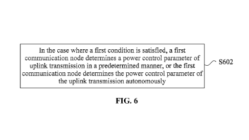
This embodiment provides a power control method. FIG. 6 is flowchart one of a
power
control method according to an embodiment of the present disclosure. As shown
in FIG. 6,
the method includes the following.
In S602, in the case where a first condition is satisfied, a first
communication node
determines a power control parameter of uplink transmission in a predetermined
manner, or
the first communication node determines the power control parameter of the
uplink
transmission autonomously.
In this embodiment, the first condition includes at least one of the
following: 1) an uplink
transmission resource being in an FRI frequency band, where the uplink
transmission
12
CA 03154507 2022-4-12
resource in the FRI frequency band may also be replaced by at least one of the
following
conditions: the first communication node being not configured with a type D
QCL parameter
or the first communication node being not configured with a spatial parameter;
2) the first
communication node being in an RRC CONNECTED mode; 3) the first communication
node being not configured with the power control parameter; 4) the power
control parameter
of the first communication node being not existed; 5) the first communication
node being
configured with or indicated at least one power control parameter; 6) the
first
communication node being configured with or indicated more than one power
control
parameter; 7) scheduling information of the uplink transmission not including
reference
signal information or spatial relation information; 8) the first communication
node being
configured or instructed to use the predetermined manner to determine the
power control
parameter; 9) the first communication node being configured or instructed to
determine the
power control parameter autonomously; or 10) the first communication node
being
configured or instructed to allow autonomous determination of the power
control parameter.
In S602, in the case where the first condition is satisfied, the first
communication node
determines the power control parameter of the uplink transmission in the
predetermined
manner, or the first communication node autonomously determines the power
control
parameter of the uplink transmission. In this manner, the first communication
node may
autonomously determine the power control parameter so as to solve the
following problem
in the related art: since a terminal does not distinguish between beams, when
scheduling the
uplink transmission, a base station cannot flexibly use change of a sending
beam to change
a corresponding power control parameter. Therefore, the flexibility of power
control is
improved.
The first communication node involved in the present application includes one
of a UE, a
terminal, a user, or a station.
In an optional embodiment of the present application, the manner in which the
first
communication node determines the power control parameter autonomously may
include:
determining, by the first communication node, an RS set for measuring a PL,
and
determining power of the uplink transmission according to the RS set for
measuring the PL.
13
CA 03154507 2022-4-12
The determining the power of the uplink transmission according to the RS set
for measuring
the PL includes: obtaining at least one PL according to part or all of RSs in
the RS set for
measuring the PL, and determining the power of the uplink transmission
according to one
or more minimum PL values among the at least one PL.
In this embodiment, the RS set for measuring the PL includes at least one of
the following:
1) the RS set for measuring the PL including at least one RS for measuring the
PL; 2) the
RS for measuring the PL including at least one of: a synchronization signal
block (SSB) or
a channel state information reference signal (CSI-RS); or 3) the RS set for
measuring the
PL including all or part of an SSB set of a second communication node and/or
all or part of
the RS set for measuring the PL configured by the second communication node
for the first
communication node.
The second communication node involved in the present application includes one
of the
following: a base station, a nodeB (NB, eNB, and gNB), a network side, or an
access point
(AP).
In another optional implementation of this embodiment, the method in the
present
embodiment may further include the following.
In S604, in the case where a second condition is satisfied, the first
communication node
sends change information of the RS for measuring the PL to a second
communication node.
In this embodiment, the second condition may include at least one of the
following: 1) a
difference between a minimum PL value in the RS set for measuring the PL and a
PL being
used being greater than a predetermined threshold; 2) an RS corresponding to
the PL
minimum value in the RS set for measuring the PL being different from an RS
corresponding
to the PL being used; 3) the RS corresponding to the minimum PL value in the
RS set for
measuring the PL not belonging to the RS set for measuring the PL configured
by the second
communication node; 4) the RS corresponding to the minimum PL value in the RS
set for
measuring the PL and an RS in the RS set for measuring the PL configured by
the second
communication node not having a QCL relation; 5) a capability of the first
communication
node supporting to send the change information of the RS for measuring the PL
sent to the
second communication node; or 6) the second communication node being
configured to
14
CA 03154507 2022-4-12
allow the first communication node to send the change information of the RS
for measuring
the PL to the second communication node.
Optionally, the change information of the RS for measuring the PL involved in
this
embodiment includes at least one of the following: 1) the difference between
the PL
minimum value in the RS set for measuring the PL and the PL being used in the
RS for
measuring the PL; 2) an indication in which the difference between the PL
minimum value
in the RS set for measuring the PL and the PL being used in the RS for
measuring the PL
exceeds a threshold; 3) a state indication in which the difference between the
PL minimum
value in the RS set for measuring the PL and the PL being used in the RS for
measuring the
PL exceeds the threshold; or 4) an RS recommended by the first communication
node for
measuring the PL.
Optionally, in this embodiment, the first communication node sends the change
information
of the RS for measuring the PL to the second communication node in one of the
following
manners: through a power headroom report (PHR); or through an independent PL
or an
MAC CE of the RS for measuring the PL. Where the MAC CE may be a MAC control
element (CE).
Optionally, in this embodiment, the determining, by the first communication
node, the
power control parameter in the predetermined manner includes one of: 1)
determining the
power control parameter of the uplink transmission according to a CORESET; and
determining the power control parameter of the uplink transmission according
to a search
space; where the CORESET refers to a control resource set; 2) determining the
power
control parameter of the uplink transmission according to a transmission
configuration
indicator (ICI) state with a minimum number in a TCI state set of an activated
physical
downlink shared channel (PDSCH); 3) determining the power control parameter of
the
uplink transmission according to a spatial relation associated with a sounding
reference
signal resource indicator (SRI) of the uplink transmission; or 4) determining
the power
control parameter of the uplink transmission according to a power control
parameter of a
sounding reference signal (SRS) resource set.
CA 03154507 2022-4-12
Optionally, the CORESET is determined according to one of' the following
characteristics:
1) a CORESET numbered 0; 2) a CORESET with a minimum number; 3) a CORESET
associated with the search space; 4) a CORESET associated with a common search
space;
5) a CORESET associated with a search space with a minimum number; 6) a
CORESET
monitored during a most recent predetermined period; or 7) a CORESET detected
on a
specific bandwidth part or carrier.
Optionally, in the present application, the search space is determined
according to one of the
following characteristics: 1) a search space numbered 0; 2) a search space
with a minimum
number; 3) a common search space; 4) a search space associated with CORESET 0;
5) a
search space monitored during a most recent predetermined period; or 6) a
search space of
a physical downlink control channel (PDCCH) for scheduling PDSCH transmission
including CORESET 0 information.
Optionally, in the present application, the determining the power control
parameter of the
uplink transmission according to the spatial relation associated with the SRI
of the uplink
transmission includes one of the following: in the case where the spatial
relation associated
with the SRI of the uplink transmission is a downlink reference signal, the
downlink
reference signal being an RS for measuring the PL of the uplink transmission;
or in the case
where the spatial relation associated with the SRI of the uplink transmission
is a periodic
downlink reference signal, the downlink reference signal being the RS for
measuring the PL
of the uplink transmission.
Optionally, in this embodiment, the power control parameter of the SRS
resource set
includes one of the following: 1) the power control parameter of the SRS
resource set
associated with the uplink transmission; 2) the power control parameter of the
SRS resource
set for a transmission configuration parameter of the uplink transmission; 3)
the power
control parameter of the SRS resource set for beam management; 4) the power
control
parameter of the SRS resource set for antenna switching; or 5) the power
control parameter
of the SRS resource set for positioning.
Embodiment two
16
CA 03154507 2022-4-12
This embodiment provides a power control method. FIG. 7 is flowchart two of a
power
control method according to an embodiment of the present disclosure. As shown
in FIG. 7,
the method includes the following.
In S702, in the case where a third condition is satisfied, a first
communication node reports
a measurement result to a second communication node.
In S704, the first communication node determines power of uplink transmission
according
to a power control parameter sent by the second communication node.
Optionally, in this embodiment, the third condition includes at least one of
the following: a
difference between a minimum PL value in an RS set for measuring a PL and a PL
of a path
loss measurement reference signal being used being greater than a preset
threshold value;
or a time interval between a current report and a previous report exceeding a
preset time
period.
Optionally, the measurement result in this embodiment includes at least one of
the following:
1) the difference between the PL minimum value in the RS set for measuring the
PL and the
PL being used in the RS for measuring the PL; 2) an indication in which the
difference
between the PL minimum value in the RS set for measuring the PL and the PL
being used
in the RS for measuring the PL exceeds a threshold; 3) a state indication in
which the
difference between the PL minimum value in the RS set for measuring the PL and
the PL
being used in the RS for measuring the PL exceeds the threshold; or 4) an
optimal RS
recommended by the first communication node for measuring the PL.
Optionally, the manner in which the first communication node reports the
measurement
result includes at least one of the following: through a PHR; through an
independent PL or
an MAC CE of a path loss measurement reference signal; or through a channel
state
information (CSI) report.
In this embodiment, the first condition includes at least one of the
following: 1) an uplink
transmission resource being in an FR1 frequency band; 2) the first
communication node
being in an RRC_CONNECTED mode; 3) the first communication node being not
configured with the power control parameter; 4) the power control parameter of
the first
communication node being not existed; 5) the first communication node being
configured
17
CA 03154507 2022-4-12
with or indicated at least one power control parameter; 6) the first
communication node
being configured with or indicated more than one power control parameter; 7)
scheduling
information of the uplink transmission not including spatial relation
information; 8) the first
communication node being configured or instructed to use the predetermined
manner to
determine the power control parameter; 9) the first communication node being
configured
or instructed to determine the power control parameter autonomously; or (10)
the first
communication node being configured or instructed to allow autonomous
determination of
the power control parameter.
In an optional embodiment of the present application, the manner in which the
first
communication node determines the power control parameter autonomously may
include:
determining, by the first communication node, an RS set for measuring a PL,
and
determining power of the uplink transmission according to the RS set for
measuring the PL.
The determining the power of the uplink transmission according to the RS set
for measuring
the PL includes: obtaining at least one PL according to part or all of RSs in
the RS set for
measuring the PL, and determining the power of the uplink transmission by
using one or
more minimum PL values among the at least one PL.
In this embodiment, the RS set for measuring the PL includes at least one of
the following:
1) the RS set for measuring the PL including at least one RS for measuring the
PL; 2) the
RS for measuring the PL including at least one of the following: a
synchronization signal
block (SSB) or a channel state information reference signal (CSI-RS); or 3)
the RS set for
measuring the PL including all or part of an SSB set of a second communication
node and/or
all or part of the RS set for measuring the PL configured by the second
communication node
for the first communication node.
In another optional implementation of this embodiment, the method in the
present
embodiment may further include the following.
In S604, in the case where a second condition is satisfied, the first
communication node
sends change information of the RS for measuring the PL to a second
communication node.
In this embodiment, the second condition may include at least one of the
following: 1) a
difference between a minimum value among at least one PL currently measured
and a PL
18
CA 03154507 2022-4-12
being used being greater than a predetermined threshold; 2) an RS
corresponding to the
minimum value among the at least one PL currently measured being different
from an RS
corresponding to the PL being used; 3) the RS corresponding to the minimum
value among
the at least one PL currently measured not belonging to the RS set for
measuring the PL
configured by the second communication node; 4) the RS corresponding to the
minimum
value among the at least one PL currently measured and an RS in the RS set for
measuring
the PL configured by the second communication node not having a QCL relation;
5) a
capability of the first communication node supporting to send the change
information of the
RS for measuring the PL sent to the second communication node; or 6) the
second
communication node being configured to allow the first communication node to
send the
change information of the RS for measuring the PL to the second communication
node.
Optionally, the change information of the RS for measuring the PL involved in
this
embodiment includes at least one of: 1) a difference between an optimal RS for
measuring
the PL and a PL being used in the RS for measuring the PL; 2) an indication in
which the
difference between the optimal RS for measuring the PL and the PL being used
in the RS
for measuring the PL exceeds a threshold; 3) a state indication in which the
difference
between the optimal RS for measuring the PL and the PL being used in the RS
for measuring
the PL exceeds the threshold; or 4) an RS recommended by the first
communication node
for measuring the PL.
Optionally, in this embodiment, the first communication node sends the change
information
of the RS for measuring the PL to the second communication node in one of the
following
manners: through an MAC CE of a PI-1R; or through an independent PL or an MAC
CE of
the RS for measuring the PL.
Optionally, in this embodiment, determining, by the first communication node,
the power
control parameter in the predetermined manner includes one of the following:
1)
determining the power control parameter of the uplink transmission according
to a
CORESET; and determining the power control parameter of the uplink
transmission
according to a search space; 2) determining the power control parameter of the
uplink
transmission according to a TCI state with a minimum number in a TCI state set
of an
19
CA 03154507 2022-4-12
activated PDSCH; 3) determining the power control parameter of the uplink
transmission
according to a spatial relation associated with an SRI of the uplink
transmission; or 4)
determining the power control parameter of the uplink transmission according
to a power
control parameter of an SRS resource set.
Optionally, the CORESET is determined according to one of the following
characteristics:
1) a CORESET numbered 0; 2) a CORESET with a minimum number; 3) a CORESET
associated with the search space; 4) a CORESET associated with a common search
space;
5) a CORESET associated with a search space with a minimum number; 6) a
CORESET
monitored during a most recent predetermined period; or 7) a CORESET detected
on a
specific bandwidth part or carrier.
Optionally, in the present application, the search space is determined
according to one of the
following characteristics: 1) a search space numbered 0; 2) a search space
with a minimum
number; 3) a common search space; 4) a search space associated with CORESET 0;
5) a
search space monitored during a most recent predetermined period; or 6) a
search space of
a PDCCH for scheduling PDSCH transmission including CORESET 0 information.
Optionally, in the present application, determining the power control
parameter of the uplink
transmission according to the spatial relation associated with the SRI of the
uplink
transmission includes one of the following: in the case where the spatial
relation associated
with the SRI of the uplink transmission is a downlink reference signal, the
downlink
reference signal is an RS for measuring the PL of the uplink transmission; or
in the case
where the spatial relation associated with the SRI of the uplink transmission
is a periodic
downlink reference signal, the downlink reference signal is the RS for
measuring the PL of
the uplink transmission.
Optionally, in this embodiment, the power control parameter of the SRS
resource set
includes one of: 1) the power control parameter of the SRS resource set
associated with the
uplink transmission; 2) the power control parameter of the SRS resource set
for a
transmission configuration parameter of the uplink transmission; 3) the power
control
parameter of the SRS resource set for beam management; 4) the power control
parameter of
CA 03154507 2022-4-12
the SRS resource set for antenna switching; or 5) the power control parameter
of the SRS
resource set for positioning.
Embodiment three
This embodiment provides a power control method. FIG. 8 is flowchart three of
a power
control method according to an embodiment of the present disclosure. As shown
in FIG. 8,
the method includes the following.
In S802, a first communication node receives a power control parameter sent by
a second
communication node.
In S804, the first communication node determines power of uplink transmission
according
to the power control parameter.
The power control parameter is determined according to at least one of the
following: an
effective time or a path loss mode.
The effective time is determined according to at least one of the following:
an occasion
when the power control parameter is received; delaying a first time; or a
sending occasion
of hybridautomatic repeat-request acknowledgement (HARQ-ACK) signaling
associated
with a physical downlink shared channel (PDSCH) carrying the power control
parameter.
A manner of determining the power control parameter according to the effective
time
includes one of the following.
1) In the case where a path loss measurement reference signal included in
power control
parameter information belongs to an RS set for measuring a PL of the first
communication
node, the power control parameter is effective after the power control
parameter is received
or after the HARQ-ACK signaling associated with the PDSCH carrying the power
control
parameter is sent.
2) In the case where the path loss measurement reference signal included in
the power
control parameter information does not belong to the RS set for measuring the
PL of the
first communication node, the power control parameter is effective after the
first time is
delayed or after the power control parameter is received and delayed for the
first time or
after the HARQ-ACK associated with the PDSCH carrying the power control
parameter is
sent and delayed for the first time.
21
CA 03154507 2022-4-12
The path loss mode involved in this embodiment includes a high layer filtering
path loss
mode or a physical layer filtering path loss mode.
In this embodiment, the path loss mode is determined according to at least one
of the
following: a physical layer filtering path loss capability of the first
communication node; or
the path loss mode configured or indicated by the second communication node.
The high layer filtering path loss mode, also referred to as a Layer 3 (L3)
filtering path loss
mode, is a mode in which a PL is determined according to reference signal
receiving power
(RSRP) of the high layer filtering. The physical layer filtering path loss
mode, also referred
to as a Layer I (Li) filtering path loss mode, is a mode in which a PL is
determined
according to the RSRP of the physical layer filtering.
In this embodiment, it is feasible that the first communication node reports
to the second
communication node whether the first communication node has a capability of
supporting
a physical layer filtering path loss. Alternatively, the second communication
node configures
the path loss mode through high layer signaling or indicates the path loss
mode to the first
communication node through MAC layer signaling or physical layer signaling.
In the case where the first communication node has the capability of
supporting the physical
layer filtering path loss, the second communication node may configure or
indicate the path
loss mode of the first communication node to be the high layer path loss mode
or the physical
layer path loss mode.
In the case where the path loss mode of the first communication node is the
physical layer
path loss mode, determining the power control parameter according to the
effective time
includes one of: the power control parameter being effective after the first
time is delayed;
the power control parameter being effective after the power control parameter
is received
and delayed for the first time; or the power control parameter being effective
after the
HARQ-ACK signaling associated with the PDSCH carrying the power control
parameter is
sent and delayed for the first time.
The first communication node receives the power control parameter in the
following manner:
the second communication node carries the power control parameter through RRC
signaling,
22
CA 03154507 2022-4-12
or the second communication node carries the power control parameter through
the MAC
CE.
In this embodiment, the first time is determined according to at least one of:
a path loss
measurement parameter indicated by power control parameter information
received at least
once; a predetermined duration; a duration configured by the second
communication node;
or a duration determined according to a capability of the first communication
node.
Power control parameter information being received or being effective before a
second time
when the uplink transmission starts is used for determining a transmit power
of the uplink
transmission.
The second time is determined by a sending occasion or a receiving occasion of
the DCI
that schedules or activates the uplink transmission, or the second time is
determined by the
capability of the first communication node. Determining the second time by the
sending
occasion or the receiving occasion of the DCI that schedules or activates the
uplink
transmission includes that the second time includes a duration from the
sending occasion or
the receiving occasion of the DCI that schedules or activates the uplink
transmission to a
starting time of the uplink transmission.
Embodiment four
This embodiment provides a sending method for uplink transmission. The method
includes
determining a sending type of uplink transmission according to reference
signal information
or a predetermined manner.
The sending type of the uplink transmission includes a first type and a second
type, and a
time interval between the uplink transmission of the first type and the uplink
transmission
of the second type is greater than or equal to a first time offset.
In this embodiment, the uplink transmission of the first type and the uplink
transmission of
the second type do not overlap in a time domain. A time sequence of the uplink
transmission
of the first type and the uplink transmission of the second type is not
limited. The time
interval between the uplink transmission of the first type and the uplink
transmission of the
second type refers to a time interval between an ending time of the earlier
transmission of
the two transmissions and a starting time of the later transmission of the two
transmissions.
23
CA 03154507 2022-4-12
Optionally, in this embodiment, the first time offset is determined according
to at least one
of the following manners: a capability of the first communication node; a
predefined value;
or a second communication node configuration value.
The first time offset determined by the capability of the first communication
node includes
an occasion when the first communication node completes the switching of a
flexible
antenna in different frequency bands.
The first time offset determined by the predefined value includes one of: 0
microseconds
(Rs), 35 ps, 140 Rs, or 900 ps.
The second communication node configuration value includes a value of the
first
communication node of which the second communication node informs the UE
through
high layer signaling, MAC layer signaling, or physical layer signaling.
Generally, the second
communication node indicates a value from one set. For example, the set
includes 0 his, 35
ps, 140 ps, or 900 ps, and one value of the set may be configured by the
second
communication node of the base station.
Optionally, in this embodiment, the sending type includes at least one of the
following
characteristics: a maximum number of ports for the uplink transmission of the
first type
being less than or equal to a maximum number of ports for the uplink
transmission of the
second type; or maximum power for the uplink transmission of the first type
being less than
maximum power for the uplink transmission of the second type.
In a second frequency band, the maximum number of ports for the uplink
transmission of
the first type is less than or equal to the maximum number of ports for the
uplink
transmission of the second type. In the second frequency band, the maximum
power for the
uplink transmission of the first type is less than the maximum power for the
uplink
transmission of the second type, and a first frequency band carries the uplink
transmission
of the first type and cannot carry the uplink transmission of the second type.
Optionally, the first frequency band is lower in frequency than the second
frequency band.
The uplink transmission of the first type is associated with a first case,
where characteristics
of the first case include at least one of the following: a flexibly
configurable antenna
operates in the first frequency band; transmission may be performed in the
first frequency
24
CA 03154507 2022-4-12
band and the second frequency band in parallel; a number of ports for
transmission in the
second frequency band is not greater than 1; a power level of the first
communication node
UE operating in the first frequency band is 3; a power level of the first
communication node
UE operating in the second frequency band is 3; maximum power of the first
communication
node UE operating in the first frequency band is 23 dBm; or maximum power of
the first
communication node UE operating in the second frequency band is 23 dBm.
In an embodiment, the uplink transmission of the first type is associated with
a second case,
and characteristics of the second case include at least one of the following:
the flexibly
configurable antenna operates in the second frequency band; transmission
cannot be
performed in the first frequency band; the number of ports for transmission in
the second
frequency band is greater than or equal to 1; maximum power for the second
frequency band
may reach 26 dBm; or a power level of the first communication node UE
operating in the
second frequency band in the second case is 2.
Optionally, a correspondence between an antenna port and a transmit antenna is
determined
according to at least one of the following: an antenna port numbered 0 being
corresponded
to a fixed transmit antenna; an antenna port numbered 1 being corresponded to
a flexible
transmit antenna; NI antenna ports with a minimum antenna port number being
corresponded to fixed MI transmit antennas, where Ni and MI are both non-zero
integers,
and NI is less than or equal to MI; N2 antenna ports with a maximum antenna
port number
being corresponded to flexibly configured M2 transmit antennas, where N2 and
M2 are both
non-zero integers, and N2 is less than or equal to M2; or the antenna port
numbered 0 being
corresponded to the fixed transmit antenna and a flexibly configured transmit
antenna.
The correspondence between the antenna port and the transmit antenna is
determined
according to at least one of the following: an antenna port of the first
frequency band
operating in the first case being corresponded to the flexibly configured
transmit antenna;
an antenna port of the second frequency band operating in the first case being
corresponded
to the fixed transmit antenna; an antenna port numbered 0 of the second
frequency band
operating in the second case being corresponded to the fixed transmit antenna;
an antenna
port numbered 1 of the second frequency band operating in the second case
being
CA 03154507 2022-4-12
corresponded to the flexibly configured transmit antenna; Ni antenna ports
with the
minimum antenna port number of the second frequency band operating in the
second case
being corresponded to MI fixed transmit antennas, where Ni and MI are non-zero
integers,
and Ni is less than or equal to Ml; N2 antenna ports with the maximum antenna
port number
of the second frequency band operating in the second case being corresponded
to M2
flexibly configured transmit antennas, where N2 and M2 are non-zero integers,
and N2 is
less than or equal to M2; or an antenna port numbered 0 of the second
frequency band
operating in the second case being corresponded to the fixed transmit antenna
and the
flexibly configured transmit antenna.
The first communication node sends the correspondence between the antenna port
and the
transmit antenna to the second communication node.
Sending, by the first communication node, the correspondence between the
antenna port and
the transmit antenna to the second communication node includes one of sending,
by the
first communication node, a correspondence between each antenna port and the
transmit
antenna to the second communication node; or sending, by the first
communication node, a
correspondence between the fixed transmit antenna and the antenna port to the
second
communication node.
Optionally, in this embodiment, determining the sending type of the uplink
transmission
according to the predetermined manner includes at least one of: determining
the sending
type of the uplink transmission according to a frame structure pattern;
determining the
sending type of the uplink transmission according to a time configuration
parameter of a
first case and/or a second case; determining the sending type of the uplink
transmission
according to the first case and/or the second case turned on or off;
determining the sending
type of the uplink transmission according to a default case; or detemfining
the sending type
of the uplink transmission according to a bandwidth part (BWP) of the
transmission.
In the case where the uplink transmission is transmission in the first
frequency band, the
sending type of the uplink transmission is the first type; and in the case
where the uplink
transmission is transmission in the second frequency band and a number of non-
zero power
26
CA 03154507 2022-4-12
transmission ports of the uplink transmission is greater than 1, the sending
type of the uplink
transmission is the second type.
Optionally, the uplink transmission in this embodiment includes at least one
of: SRS
transmission, PUSCH transmission, or PUCCH transmission.
The reference signal information includes one of: an SRS resource, an SRS
resource set, or
an SRS resource indicator.
Optionally, in this embodiment, the reference signal information includes at
least one of the
following characteristics: the reference signal information being associated
with the first
type and/or the second type; or the reference signal information being
associated with a first
case and/or a second case.
The reference signal information being associated with the first case and/or
the second case
includes one of the following: the SRS resource being associated with the
first case and/or
the second case; or the SRS resource set being associated with the first case
and/or the
second case.
Optionally, in this embodiment, association of the reference signal
information with the first
case and/or the second case is determined according to one of the following:
number of the
reference signal information; a function of the reference signal information;
or
pre c onfigure d information.
Association of the reference signal information with the first type and/or the
second type is
determined according to one of the following: number of the reference signal
information;
a function of the reference signal information; or preconfigured information.
Different SRS resources of the SRS resource set, which are respectively
associated with the
first case (or the first type) and the second case (or the second type), have
same time domain
parameters.
Different SRS resources of the SRS resource set, which are respectively
associated with the
first case (or the first type) and the second case (or the second type), have
same frequency
domain parameters.
All SRS resources with a port number of 1 in the SRS resource set correspond
to fixed
transmit antennas, and N3 SRS resources with the minimum number with a port
number of
27
CA 03154507 2022-4-12
1 in the SRS resource set correspond to M3 fixed transmit antennas. Where N3
and M3 are
non-zero integers, and N3 is less than or equal to M3.
Optionally, in this embodiment, determining the sending type of the uplink
transmission
according to the reference signal information or the predetermined manner
includes at least
one of the following: the sending type of SRS transmission associated with the
first case
being the first type; the sending type of the SRS transmission associated with
the second
case being the second type; the sending type of PUSCH transmission with
reference to the
reference signal information associated with the first case being the first
type; the sending
type of the PUSCH transmission with reference to the reference signal
information
associated with the second case being the second type; scheduling information
includes that
the sending type of the PUSCH transmission associated with the reference
signal
information of the first case being the first type; scheduling information
includes that the
sending type of the PUSCH transmission associated with the reference signal
information
of the second case being the second type; the sending type of the SRS
transmission
associated with different SRS resources of the first case and the second case
of an SRS
resource set being the second type; in the case where the sending type of the
SRS
transmission associated with the second case is the first type, only sending
the SRS
transmission whose number of ports are supported by the first type is sent,
wherein the
number of ports of the SRS transmission is ranged in an ascending order; the
uplink
transmission of the first type and the uplink transmission of the second type
referring to the
reference signal information being associated with the first case and the
reference signal
information associated with the second case, respectively; or the uplink
transmission of the
first type and the uplink transmission of the second type respectively
referring to the
reference signal information associated with the second case.
For example, the number of ports supported by the SRS transmission associated
with the
second case is 2, the number of ports supported by the first type is assumed
to be 1, the SRS
transmission associated with the second case only sends the SRS transmission
of port 0.
Determining the sending type of the uplink transmission according to the
reference signal
information or the predetermined manner further includes at least one of the
following: the
28
CA 03154507 2022-4-12
sending type of the PUCCH transmission with reference to the reference signal
information
associated with the first case being the first type; or the sending type of
the PUCCH
transmission with reference to the reference signal information associated
with the second
case being the second type.
The PUSCH transmission with reference to the reference signal information
associated with
the first case refers to scheduling information or grant information of the
PUSCH
transmission, or the DCI including the scheduling information including the
reference signal
information associated with the first case.
The PUCCH transmission associated with the reference signal information
associated with
the first case means that spatial relation information of the PUCCH
transmission includes
the reference signal information.
Referenced reference signal information of the uplink transmission means that
the
scheduling information of the uplink transmission includes the reference
signal information.
That is, the sending parameter of the uplink transmission is determined by
referenced
reference signal information. =The sending parameter includes at least one of:
an antenna
port, a filter parameter, or a precoding parameter.
Optionally, in this embodiment, the time interval between the uplink
transmission of the
first type and the uplink transmission of the second type being greater than
or equal to the
first time offset includes one of the following:
In the case where the uplink transmission of the first type and the uplink
transmission of the
second type belong to a same SRS resource set, determining the first time
offset according
to a time offset configured in the SRS resource set or a predetermined value;
or in the case
where the uplink transmission of the first type and the uplink transmission of
the second
type belong to different SRS resource sets, determining the first time offset
according to the
predetermined value or a BWP or a component carrier (CC) time offset of SRS
transmission
or according to a time offset of a first communication node of the UE, where
in the case
where different SRS resource sets are used for distinguishing the first case
and the second
case, the second communication node of the base station needs to indicate an
SRS resource
set ID to the first communication node HE.
29
CA 03154507 2022-4-12
This embodiment is described hereinafter in conjunction with specific
embodiments.
As shown in FIG. 9, two transmissions are deployed in two frequency bands, and
carrier
aggregation (CA) is used as an example for description here, where CC I and
CC2 represent
two frequency bands. CC is a component carrier in CA. CC I is a frequency band
with a
lower frequency (referred to as a lower frequency band for short), and CC2 is
a frequency
band with a higher frequency (referred to as a higher frequency band for
short). Generally,
one antenna is sufficient for transmission in the lower frequency band, while
multiple
antennas, for example, two antennas, may be used for transmission in the
higher frequency
band for better performance. In this manner, the TIE needs three antennas to
achieve
independent transmission of the preceding two frequency bands. In fact, from
the
perspective of cost reduction, the UE only needs to be configured with two
antennas, one of
which is fixed in one frequency band (referred to as a fixed antenna for
short), for example,
the higher frequency band CC2, and the other one of which is a flexibly
configured antenna
(referred to as a flexible antenna for short) and may be time-divisionally
switched between
CCI and CC2. There are two cases in the time domain, which are the first case
and the
second case and also referred to as case 1 and case 2. The first case and the
second case may
also be referred to as a case numbered 1 and a case numbered 2, respectively.
In the first
case, the flexibly configurable antenna operates in the lower frequency band,
and
independent transmission of one antenna in the lower frequency band and one
antenna in
the higher frequency band is feasible. In the second case, the flexibly
configurable antenna
operates in the higher frequency band, transmission of this antenna and
transmission of a
fixedly configured antenna are performed at the same time, and in this case,
the lower
frequency band has no antenna available and transmission cannot be performed
on the lower
frequency band.
In addition to the case where the preceding two frequency bands are CC! and
CC2, the two
frequency bands may also be replaced by other scenarios, for example, the
lower frequency
band is long term evolution (LIE), and the higher frequency band is NR.
Alternatively, the
lower frequency band is a supplementary uplink (SUL), and the higher frequency
band is
an uplink (UL) (also referred to as a non-SUE UL and a normal UL).
CA 03154507 2022-4-12
The UE operates in the first case when the UE needs to send transmission in a
low frequency
band. The UE operates in the second case when the UE needs to use two ports
for
transmission in a high frequency band, or when the UE needs to send
transmission with high
power. If there are no requirements for another case, the UE keeps operating
in the current
case.
In the preceding scenario, a relation among the first case, the second case,
the SRS
transmission and the PUSCH transmission is not clear. Description is made
below.
Number of a case to which a transmission period belongs, that is, the first
case or the second
case, is determined according to at least one of the following: a
predetermined manner.
Determining number of the case to which the transmission period belongs
according to the
predetermined manner includes one of the following: time parameters of the
first case and
the second case configured by the base station.
In an implementation of this embodiment, a period of the first case and a
period of the
second case are repeated in a periodic manner. For example, the base station
configures the
period of the first case, the period of the second case, and the time or
proportion of the first
case or the second case in the period.
In another implementation of this embodiment, a transmission period is
determined to be
belonged to the first case and the second case according to a preconfigured
frame structure
pattern.
The base station turns on or off the first case, and/or the base station turns
on or off the
second case.
1) The base station only configures or indicates the first case or the second
case being turned
on or being turned off. In this case, all time periods may only belong to the
first case or the
second case. That is, in the case where the first case is turned off, the
second case is turned
on; and in the case where the first ease is turned on, the second case is
turned off
2) The base station configures or indicates the first case and the second case
being turned
on or being turned off The two cases cannot be turned on at the same time, but
can be turned
off at the same time.
3
CA 03154507 2022-4-12
In a default case, in the case where an interval between an ending time of the
PDCCH
including scheduling information of the transmission and a starting time of
the transmission
is less than a predetermined threshold, that is, a capability of switching to
a case associated
with the transmission before the starting time of the transmission is not
achieved, then the
default case is used for determining number of a case of the transmission
period, such as the
first case.
For the BWP, different cases are associated with different bandwidth parts
(BWPs). The
case of uplink transmission is indicated by different BWP IDs.
For number of a case associated with the transmission, number of a case to
which the
transmission period belongs is determined according to number of the case
associated with
the transmission.
1) Number associated with the transmission is consistent with number of the
case to which
the transmission period belongs.
For example, when the UE sends the SRS transmission, in the case where the SRS
transmission is associated with the first case, a time period occupied by the
SRS
transmission belongs to the first case.
For example, when the UE sends the PUSCH transmission, in the case where the
PUSCH
transmission is associated with the second case, a time period occupied by the
PUSCH
transmission belongs to the second case.
2) In the case where an interval between an ending time of the PDCCH including
scheduling
information of the transmission and a starting time of the transmission is
greater than or
equal to a predetermined threshold, that is, a capability of switching to a
case associated
with the transmission before the starting time of the transmission is not
achieved, then
number associated with the transmission is consistent with number of a case
associated with
the transmission period.
The UE determines association of the reference signal with the first case
and/or the second
case. The reference signal includes at least one of: an SRS, a CSI-RS, a DMRS,
or an SSB.
The SRS is used as an example for description below.
32
CA 03154507 2022-4-12
The SRS information includes one of the following: an SRS resource, an SRS
resource set,
or an SRS resource indicator.
Association of the SRS information with the first case and/or the second case
is determined.
Determining the association of the SRS information with the first case and/or
the second
case includes one of the following.
A function of configuring the SRS information by the base station is the first
case and/or the
second case, that is, the SRS information is associated with the first case
and/or the second
case, respectively.
A function of the SRS information includes at least one of: the first case or
the second case.
For example, in the case where the SRS information is the SRS resource set,
and a function
of the SRS resource set is configured to be the first case or the second case,
the SRS resource
set is associated with the first case or the second case, respectively. In the
case where the
SRS information is the SRS resource, and a function of the SRS resource is
configured to
be the first case or the second case, the SRS resource is associated with the
first case or the
second case, respectively.
The association of the SRS information with the first case and/or the second
case is
determined according to number of the SRS information.
1) SRS information with a minimum number is associated with the first case,
and SRS
information with a maximum number is associated with the second case.
For example, the SRS resource set has two SRS resources, numbered 0 and 1,
respectively.
In the case where the reference signal information is the SRS resource, the
SRS resource
numbered 0 is associated with the first case, and the SRS resource numbered 1
is associated
with the second case.
For example, the SRS resource set has three SRS resources, numbered 0, 1, and
2,
respectively, then the SRS resource numbered 0 is associated with the first
case, and the
SRS resources numbered 1 and 2 are associated with the second case. The SRS
resource
numbered 0 is configured with one port, and the SRS resource numbered 1 is
configured
with two ports.
33
CA 03154507 2022-4-12
2) The SRS information with the minimum number is associated with the second
case, and
the SRS information with the maximum number is associated with the first case.
The association of the SRS information with the first case and/or the second
case is
determined according to preconfig,ured information.
For example, in the case where the SRS information is the SRS resource set,
the SRS
resource set is configured by higher layer signaling to be associated with the
first case or
the second case. In the case where the SRS information is the SRS resource,
the SRS
resource is configured by higher layer signaling to be associated with the
first case or the
second case.
The UL determines a sending mode of the SRS transmission according to
association of the
SRS with the first case and/or the second case. Determining, by the UE, the
sending mode
of the SRS transmission according to the association of the SRS with the first
case and/or
the second case includes one of the following.
The SRS transmission is sent only in a time period of a case associated with
the SRS.
Sending the SRS transmission only in the time period of the case associated
with the SRS
includes one of the following.
In the case where number of a case to which a transmission period belongs is
determined
according to a predetermined method, the SRS associated with the first case is
sent in a time
period of the first case, and the SRS associated with the second case is sent
in a time period
of the second case.
In the case where number of the case to which the transmission period belongs
is determined
according to number of a case associated with the transmission, in the case
where an interval
between an end time of the PDCCH including scheduling information of the SRS
transmission and a starting time of the SRS transmission is greater than or
equal to a
predetermined threshold, that is, a capability of switching to a case
associated with the SRS
transmission before the starting time of the SRS transmission is achieved,
then number
associated with the SRS transmission is consistent with number of a case to
which an SRS
transmission period belongs; and in the case where the interval between the
end time of the
PDCCH including scheduling information of the transmission and the starting
time of the
34
CA 03154507 2022-4-12
SRS transmission is less than the predetermined threshold, that is, the
capability of
switching to the case associated with the SRS transmission before the starting
time of' the
transmission is not achieved, then the default case is used for determining
number of a case
of the SRS transmission period, such as the first case.
In the case where number of the case to which the transmission period belongs
is determined
according to number of the case associated with the transmission, a time
offset between the
SRS resource associated with the first case and the SRS resource associated
with the second
case in the SRS resource set is predetermined or configured by RRC signaling.
Sending of the SRS transmission associated with the first case in the time
period of the
second case is supported.
In the case where the UE is in the second case, the SRS transmission
associated with the
first case can be sent without switching to the first case. The second case
may be a case to
which a time period of the transmission determined according to the
predetermined manner
or number of the case associated with the transmission belongs.
For example, in the case where an SRS resource set is configured with SRS
resource 1 and
SRS resource 2 that are associated with the first case and the second case,
respectively. In
the case where the UE is in the first case, only SRS resource 1 is sent; and
in the case where
the UE is in the second case, both SRS resource 1 and SRS resource 2 may be
sent without
switching to the first case to send SRS resource 1.
For example, in the case where an SRS resource set is configured with SRS
resource 1, SRS
resource 2, and SRS resource 3, SRS resource 1 is associated with the first
case and supports
1 port, SRS resource 2 is associated with the second case and supports 1 port,
and SRS
resource 3 is associated with the second case and supports 2 ports. In the
case where the HE
is in the first case, only SRS resource 1 is sent. In the case where the UE is
in the second
case, SRS resource 1, SRS resource 2, and SRS resource 3 may be sent without
switching
to the first case to send SRS resource 1.
An SRS sent only in a time period of the second case is supported, that is,
the SRS resource
associated with the first case is not sent.
CA 03154507 2022-4-12
For the PUSCH transmission associated with the first case, one of' the
following is used for
determining a sending parameter for the PUSCH transmission associated with the
first case.
A measurement result of part of ports in the SAS that is associated with the
second case and
sent in the time period of the second case.
The part of the ports in the SRS associated with the second case refers to
ports corresponding
to ports of the SRS associated with the first case. For example, SRS resource
1 is associated
with the second case and configured with 2 ports, where port 0 being
corresponded to the
port of the SRS associated with the first case so that a measurement result of
port 0 in the 2
ports of SRS resource 1 may be used as a measurement result of the SRS
associated with
the first case.
A correspondence between part of ports in the SRS associated with the second
case and the
ports of the SRS associated with the first case being predefined or determined
by the LIE
and reported to the base station.
Antennas of part of ports in the SRS that is associated with the second case
and sent in the
time period of the second case are consistent with antennas of ports of the
SRS associated
with the first case. For example, SRS resource 1 is associated with the second
case and
configured with 2 ports, where port 0 being corresponded to a fixed antenna,
port 1 being
corresponded to a flexibly configured antenna, and the SRS resource associated
with the
first case also being corresponded to a fixed antenna. Therefore, the
measurement result of
port 0 of SRS resource I may be used as the measurement result of the SRS
associated with
the first case.
A correspondence between ports and antennas is described below.
In manner 1, a fixedly configured antenna being corresponded to port 0, and a
flexibly
configured antenna being corresponded to port 1.
In manner 2, a fixedly configured antenna and a flexibly configured antenna
correspond to
port 0.
In manner 3, a correspondence among a fixedly configured antenna and a
flexibly
configured antenna and number of a port is flexibly configured.
36
CA 03154507 2022-4-12
A measurement result of the SRS that is associated with the first case and
sent in the time
period of the second case.
A measurement result of the SRS that is associated with the first case and
sent in the time
period of the first case.
For the PUSCH transmission associated with the first case, the closest result
to the PUSCH
transmission among the preceding results is used for determining the sending
parameter of
the PUSCH transmission associated with the first case.
1) The SRS resource may not be associated with number of a case, and the
measurement
results of the SRS are selected according to the first case or the second case
to which the
PUSCH transmission belongs. For example, the PUSCH transmission transmitted in
the
time period of the first case uses the measurement result of port 0 of the
SRS. The PUSCH
transmission transmitted in the time period of the second case uses a
measurement result of
the port of the PUSCH corresponding to the SRS. The port of the PUSCH may be
one virtual
port, or one or two of two ports.
2) Time-frequency domain resources of multiple SRS resources associated with
different
case numbers are the same, only the SRS resource of one port is sent in the
time period of
the first case, and the SRS resource of all ports is sent in the time period
of the second case.
In the case where full power transmission mode 1 is supported, the SRS
resource set includes
two SRS resources that are configured with 1 port and 2 ports, respectively.
The two SRS
resources are associated with the first case and the second case,
respectively.
In the case where full power transmission mode 2 is supported, the SRS
resource set includes
two SRS resources that are configured with 1 port and 1 port, respectively.
The two SRS
resources are associated with the first case and the second case,
respectively.
In the case where a multi-beam and multi-spatial relation or a multi-antenna
panel is
supported, in the case where the full power transmission mode 1 is supported,
in the SRS
resource set, each beam or spatial relation or an SRS resource group
associated with an
antenna panel includes 2 SRS resources that are configured with 1 port and 2
ports,
respectively. The 2 SRS resources are associated with the first case and the
second case,
respectively.
37
CA 03154507 2022-4-12
In the case where a multi-beam and multi-spatial relation or a multi-antenna
panel is
supported, in the case where the full power transmission mode 2 is supported,
in the SRS
resource set, each beam or spatial relation or an SRS resource group
associated with an
antenna panel includes 2 SRS resources that are configured with 1 port and I
port,
respectively. The 2 SRS resources are associated with the first case and the
second case,
respectively.
A sending manner of uplink transmission is determined according to reference
signal
information or a predetermined manner. The sending manner of the uplink
transmission
includes one of the following: a sending period of the uplink transmission
belonging to the
first case; or the sending period of the uplink transmission belonging to the
second case.
The uplink transmission includes at least one: SRS transmission, PUSCH
transmission, or
PUCCH transmission. A relation among the PUSCH and the SRS and the cases is
described
below with the PUSCH transmission as an example.
In the case where the uplink transmission is the PUSCH transmission, the
reference signal
information is the SRI included in the DCI that schedules the PUS CH
transmission.
For example, the base station schedules or triggers the UE to send the PUSCH
transmission,
an SRS resource indicator (SRI) is indicated. The SRI is an index of the SRS
resource in the
SRS resource set, where a function of the SRS resource set is the same as a
transmission
configuration parameter of the PUSCH. The PUSCH transmission is consistent
with a case
associated with the SRS resource indicated by the SRI, such as the first case
or the second
case.
In the case where the uplink transmission is the PUSCH transmission, the
reference signal
information is the SRS resource set or number of the SRS resource set included
in the DCI
that schedules the PUSCH transmission.
For example, the base station schedules or triggers the UE to send the PUSCH
transmission,
number of the SRS resource set and the SRI are indicated. The SRI is an index
of the SRS
resource in the SRS resource set, where a function of the SRS resource set
being the same
as a transmission configuration parameter of the PUSCH. The PUSCH transmission
is
38
CA 03154507 2022-4-12
consistent with the case associated with the SRS resource set, such as the
first case or the
second case.
Different SRS resources are associated with different cases, and an associated
case is
obtained through the SRI when the PUSCH is scheduled.
Different SRS resource sets are associated with different cases, and an
associated case is
obtained through number of the SRS resource set when the PUS CH is scheduled.
In the case where number of the case to which the transmission period belongs
is determined
according to the predetermined manner, the base station ensures that a case
associated with
scheduled PUSCH transmission is consistent with the case to which the
transmission period
belongs.
In the case where the case associated with the scheduled PUSCH transmission is
inconsistent with the case to which the transmission period belongs, in the
case where the
PUSCH transmission associated with the second case is sent in the time period
of the first
case, the PUSCH transmission is sent using only one port.
In the case where the case associated with the scheduled PUSCH transmission is
inconsistent with the case to which the transmission period belongs, in the
case where the
PUSCH transmission associated with the first case is sent in the time period
of the second
case, the PUSCH transmission is only sent by using one port corresponding to
the first case
among multiple ports in the second case.
In the case where number of the case to which the transmission period belongs
is determined
according to number of the case associated with the transmission, an interval
between
scheduling information of the transmission and the transmission is greater
than a
predetermined threshold. In this manner, it is ensured that there is enough
time for the LIE
to switch between different cases.
For the PUSCH transmission, reference is made to the SRS that is consistent
with the case
associated with the PUSCH transmission. For example, for CC2, the case
associated with
the SRS resource corresponding to the SRI in the DCI including the scheduling
information
of the PUSCH transmission is the same as the case associated with the PUSCH
transmission.
The following two cases are included: in the case where the case associated
with the PUSCH
39
CA 03154507 2022-4-12
is determined according to a time domain parameter of the PUSCH transmission,
that is,
number of the case to which the transmission period belongs is determined
according to the
predetermined manner, then the case associated with the SRS resource
corresponding to the
SRI is consistent with the case associated with the PUSCH transmission; in the
case where
number of the case to which the transmission period belongs is determined
according to
number of the case associated with the transmission, the case associated with
the PUSCH is
also consistent with the case associated with the SM.
In another embodiment, for the PUSCH transmission associated with the first
case, reference
may be made to the SRS associated with the second case. For example, the SRS
resource
associated with the second case is configured with 2 ports, and for the PUSCH
transmission
associated with the first case, reference is made to 1 port among the 2 ports.
A transmitted precoding matrix indicator (TPMI) is described below with
reference to Table
1.
In the case where the PUSCH transmission is associated with the first case,
the PUSCH
transmission is one-port transmission, and no indication of TPMI is required.
In the case where the PUSCH transmission is associated with the second case
and the
number of ports configured by the SRS resource associated with the SRI is 1,
then the
PUSCH transmission is one-port transmission, and no indication of TPMI is
required.
In the case where the PUSCH transmission is associated with the second case
and the
number of ports configured by the SRS resource associated with the SRI being
greater than
or equal to 1, then the PUSCH transmission still requires the indication of
TPMI. Assuming
that the number of ports configured by the SRS resource associated with the
SRI is 2, the
TPMI is parsed by a precoding codebook with 2 ports.
In the case where the UE operates in the second case, the base station
schedules the UE to
send the PUSCH transmission, and a codeword of the TPMI is ¨1 111. In the case
where
V2 0
an antenna corresponding to port 0 is a fixed antenna, the PUSCH transmission
may be a
transmission associated with the second case or a transmission associated with
the first case.
In the case where the antenna corresponding to port 0 is a flexible antenna,
the PUSCH
transmission is a transmission associated with the second case.
CA 03154507 2022-4-12
On a second carrier, the first case and the second case may be distinguished
by the TPMI.
The second case supports a precoding codebook with 2 ports, while the first
case can only
use part of codewords. For example, the transmission of the second case may
use all
codewords in the table below, while the transmission of the first case can
only use one
codeword 111
In the case where the UE operates in the second case, a first PUSCH
transmission uses the
TPMI with a codeword of ¨1 111 and a second PUS CH transmission uses other
codewords,
0
a time interval between the first PUSCH transmission and the second PUSCH
transmission
needs to be greater than a predetermined time.
A switching time between transmission sent in the first case and transmission
sent in the
second case, that is, between an ending time of the transmission sent earlier
and a starting
time of the transmission sent later, is not less than a predetermined time
interval or not less
than a time interval determined according to a capability of the UE.
On the second carrier, SRI! is used as a reference for PUSCH transmission 1
ending at an
occasion ti, and SRI2 is used as a reference for PUSCH transmission 2 starting
at an
occasion t2, where the an occasion ti is earlier than the occasion t2, SRI! is
associated with
the first case, SRI2 is associated with the second case, and a difference
between ti and t2 s
not less than a predetermined time interval or not less than the time interval
determined
according to the capability of the UE.
On the second carrier, SRI2 is used as a reference for PUSCH transmission 3
ending at an
occasion t3, and SRI1 is used as a reference for PUSCH transmission 4 starting
at an
occasion t4, where the an occasion t3 is earlier than the occasion t4, SRI1 is
associated with
the first case, SRI2 is associated with the second case, and a difference
between t3 and t4 is
not less than a predetermined time interval or not less than the time interval
determined
according to the capability of the UE.
In the present application, the first case being corresponded to the first
type, and the second
case being corresponded to the second type.
41
CA 03154507 2022-4-12
Non-coh UE Full coh LTE
Mode I Rank I Rankl
q11 1 ii
1111 q11
0 1
Rank 2 FC
I I- 1 1 111 1 1111
VZ [IL 1
Vikij
1 I"
o 1 Rank 2
po1 ill i1 1[1 i1
Lo 1
j 2 Li ¨11j 2 Li ¨ j
Mode 2 Rank 1 Rank!
Di i Fa] 101
Ld1,/ 2 L ¨,_ I J
1/2 Lu] L I
Rank 2 1-1I I I- 111 1 1111
1 1 1 rl
.\/. [11] ,\/.
1 01
..\3.11_0 11] Rank 2
1 [1 01 ill 1 ]
111 1 ]
ILO 11] ¨2[1 ¨11] ¨2
¨1]
From the description of the preceding embodiments, it is to be understood by
those skilled
in the art that the method of the preceding embodiments may be implemented by
means of
software plus a general-purpose hardware platform, or, of course, may be
implemented by
hardware. Based on such understanding, the technical solution provided by the
present
application may be embodied in the form of a software product. The computer
software
product is stored in a storage medium (such as a read-only memory (ROM), a
random-access
42
CA 03154507 2022-4-12
memory (RAM), a magnetic disk or an optical disk) and several instructions are
included
for enabling a terminal device (which may be a mobile phone, a computer, a
server or a
network device) to perform the method described in embodiments of the present
application.
Embodiment five
This embodiment further provides a power control apparatus. The apparatus is
used for
implementing the embodiments and optional embodiments described above. What
has been
described being not repeated herein. As used below, the term "module" may be
software,
hardware or a combination of software and hardware capable of implementing
predetermined functions. The apparatus in the embodiments described below may
be
implemented by software, but implementation by hardware or by a combination of
software
and hardware is also possible and conceived.
FIG. 10 is block diagram one of a power control apparatus according to an
embodiment of
the present disclosure. The apparatus is applied to a first communication node
side. As
shown in FIG. 10, the apparatus includes a first determination module 102
configured to, in
the case where a first condition is satisfied, determine a power control
parameter of uplink
transmission in a predetermined manner, or trigger that the first
communication node
determines the power control parameter of the uplink transmission
autonomously.
Embodiment six
FIG. 11 is block diagram two of a power control apparatus according to an
embodiment of
the present disclosure. The apparatus is applied to a first communication node
side. As
shown in FIG. 11, the apparatus includes a reporting module 112 configured to,
in the case
where a third condition is satisfied, report a measurement result to a second
communication
node; and a second determination module 114 coupled and connected to the
reporting
module 112 and configured to determine power of uplink transmission according
to a power
control parameter sent by the second communication node.
Optionally, in this embodiment, the third condition includes at least one of
the following: a
difference between an optimal PL-RS and a PL of the PL-RS being used being
greater than
a preset threshold value; or a time interval between a current report and a
previous report
exceeds a preset time period.
43
CA 03154507 2022-4-12
Optionally, in this embodiment, the measurement result includes at least one
of the
following: 1) a difference between an optimal RS for measuring the PL and a PL
being used
in the RS for measuring the PL; 2) an indication in which the difference
between the optimal
RS for measuring the PL and the PL being used in the RS for measuring the PL
exceeds a
threshold; 3) a state indication in which the difference between the optimal
RS for measuring
the PL and the PL being used in the RS for measuring the PL exceeds the
threshold; or 4)
an optimal RS recommended by the first communication node for measuring the
PL.
Optionally, the manner in which the first communication node reports the
measurement
result includes at least one of the following: through an MAC CE of a PHR;
through an
MAC CE of an independent PL or PL-RS; or through a CSI report.
Embodiment seven
FIG. 12 is block diagram three of a power control apparatus according to an
embodiment of
the present disclosure. The apparatus is applied to a first communication node
side. As
shown in FIG. 12, the apparatus includes a receiving module 122 configured to
receive a
power control parameter sent by a second communication node; and a third
determination
module 124 configured to determine power of uplink transmission according to
the power
control parameter. Where an effective time of the power control parameter is
determined
according to at least one of the following: in the case where PL-RS included
in power control
parameter information belongs to an RS set for measuring a PL of the first
communication
node, the power control parameter being effective after correctly received;
and in the case
where the PL-RS included in the power control parameter information not
belonging to the
RS set for measuring the PL of the first communication node, the power control
parameter
being effective after correctly received for a first time.
Optionally, in this embodiment, the receiving module 102 receives the power
control
parameter in the following manner: the second communication node carries the
power
control parameter through RRC signaling, or the second communication node
carries the
power control parameter through an MAC CE.
44
CA 03154507 2022-4-12
Optionally, the first time is determined according to at least one of the
following manners:
after the PL-RS indicated by the power control parameter information is sent
at least once;
a predefined duration; or a duration determined according to a capability of
the UE.
Power control parameter information received or effective before a second time
when the
uplink transmission starts is used for determining a transmit power of the
uplink
transmission.
Optionally, the second time is determined by a sending or receiving time of
the DCI that
schedules or activates the uplink transmission, or the second time is
determined by the
capability of the UE.
Optionally, determining the second time by the sending or receiving time of
the DCI that
schedules or activates the uplink transmission includes that the second time
includes a
duration from the sending or receiving time of the DCI that schedules or
activates the uplink
transmission to a starting time of the uplink transmission.
Embodiment eight
An embodiment of the present disclosure provides a sending apparatus for
uplink
transmission. The apparatus is applied to a first communication node side. The
apparatus
includes a fourth determination module configured to determine a sending type
of uplink
transmission according to reference signal information or a predetermined
manner.
The sending type of the uplink transmission includes a first type and a second
type; and a
time interval between the uplink transmission of the first type and the uplink
transmission
of the second type is greater than or equal to a first time offset.
It is to be noted that the various modules described above may be implemented
by software
or hardware. An implementation by hardware may, but may not necessarily, be
performed
in the following manners: the various modules described above are located in
the same
processor, or the various modules described above are located in their
respective processors
in any combination form.
Embodiment nine
CA 03154507 2022-4-12
An embodiment of the present application further provides a storage medium.
The storage
medium stores a computer program which is configured to, when executed,
perform the
steps in any one of the preceding method embodiments.
Optionally, in this embodiment, the preceding storage medium may be configured
to store
a computer program for performing the following.
In Si, in the case where a first condition is satisfied, a first communication
node determines
a power control parameter of uplink transmission in a predetermined manner, or
the first
communication node determines the power control parameter of the uplink
transmission
autonomously.
Optionally, in this embodiment, the preceding storage medium may be configured
to store
a computer program for performing the following.
In S3, in the case where a third condition is satisfied, a first communication
node reports a
measurement result to a second communication node.
In S2, the first communication node determines power of uplink transmission
according to
a power control parameter sent by the second communication node.
Optionally, in this embodiment, the preceding storage medium may be configured
to store
a computer program for performing the following.
In Si, a first communication node receives a power control parameter sent by a
second
communication node.
In S2, the first communication node determines power of uplink transmission
according to
the power control parameter. Where an effective time of the power control
parameter is
determined according to at least one of the following: in the case where PL-RS
included in
power control parameter information belongs to an RS set for measuring a PL of
the first
communication node, the power control parameter being effective after
correctly received;
and in the case where the PL-RS included in the power control parameter
information not
belonging to the RS set for measuring the PL of the first communication node,
the power
control parameter being effective after correctly received for a first time.
Optionally, in this embodiment, the preceding storage medium may be configured
to store
a computer program for performing the following.
46
CA 03154507 2022-4-12
In Si, a sending type of uplink transmission is determined according to
reference signal
information or a predetermined manner.
The sending type of the uplink transmission includes a first type and a second
type; and a
time interval between the uplink transmission of the first type and the uplink
transmission
of the second type is greater than or equal to a first time offset.
Optionally, in this embodiment, the storage medium may include, but is not
limited to, a
USB disk, an ROM, an RAM, a mobile hard disk, a magnetic disk, an optical disk
or another
medium capable of storing computer programs.
An electronic apparatus is further provided in an embodiment of the present
application and
includes a memory and a processor. The memory stores a computer program, and
the
processor is configured to execute the computer program to perform the steps
in any one of
the preceding method embodiments.
Optionally, the electronic apparatus may further include a transmission device
and an
input/output device. Both the transmission device and the input/output device
are connected
to the processor.
Optionally, in the embodiment, the processor may be configured to perform the
following
through a computer program.
In Si, in the case where a first condition is satisfied, a first communication
node determines
a power control parameter of uplink transmission in a predetermined manner, or
the first
communication node determines the power control parameter of the uplink
transmission
autonomously.
Optionally, in the embodiment, the processor may be configured to perform the
following
through a computer program.
In S3, in the case where a third condition is satisfied, a first communication
node reports a
measurement result to a second communication node.
In S2, the first communication node determines power of uplink transmission
according to
a power control parameter sent by the second communication node.
Optionally, in the embodiment, the processor may be configured to perform the
following
through a computer program.
47
CA 03154507 2022-4-12
In Si, a first communication node receives a power control parameter sent by a
second
communication node.
In S2, the first communication node determines power of uplink transmission
according to
the power control parameter; where an effective time of the power control
parameter is
determined according to at least one of the following: in the case where PL-RS
included in
power control parameter information belongs to an RS set for measuring a PL of
the first
communication node, the power control parameter being effective after
correctly received;
and in the case where the PL-RS included in the power control parameter
information not
belonging to the RS set for measuring the PL of the first communication node,
the power
control parameter being effective after correctly received for a first time.
Optionally, in the embodiment, the processor may be configured to perform the
following
through a computer program.
In Si, a sending type of uplink transmission is determined according to
reference signal
information or a predetermined manner.
The sending type of the uplink transmission includes a first type and a second
type; and a
time interval between the uplink transmission of the first type and the uplink
transmission
of the second type is greater than or equal to a first time offset.
Optionally, for specific examples in this embodiment, reference may be made to
the
examples described in the embodiments and optional embodiments described
above. Details
are not repeated here.
Apparently, it should be understood by those skilled in the art that each of
the preceding
modules or steps of the present disclosure may be implemented by a general-
purpose
computing apparatus, the modules or steps may be concentrated on a single
computing
apparatus or distributed on a network composed of multiple computing
apparatuses, and
optionally, the modules or steps may be implemented by program codes
executable by the
computing apparatus, so that the modules or steps may be stored in a storage
apparatus and
executed by the computing apparatus. In some circumstances, the illustrated or
described
steps may be executed in sequences different from those described herein, or
the modules
or steps may be made into various integrated circuit modules separately, or
multiple modules
48
CA 03154507 2022-4-12
or steps therein may be made into a single integrated circuit module for
implementation. In
this manner, the present application is not limited to any particular
combination of hardware
and software.
49
CA 03154507 2022-4-12