Note: Descriptions are shown in the official language in which they were submitted.
CA 03154924 2022-03-17
Control Strategy for Hot Surface Igniter
Technical Field
The disclosure relates to a control strategy, and in particular to a
temperature change control
strategy for a hot surface igniter in a working process.
Backdround
Combustion devices in regions/countries such as China usually adopt electric
spark ignition.
However, the electric spark ignition has problems such as unreliable ignition,
deflagration, and
electromagnetic interference. The unreliable ignition is because the electric
spark ignition is easily
affected by factors such as temperature, humidity, ignition gap, arc leakage,
and pollution. Therefore,
North American countries with many types of the combustion devices and more
advanced
combustion device application technologies adopt a hot surface ignition
technology. On the basis of
the hot surface ignition technology, after a hot surface igniter reaches a
high temperature in advance,
combustible gas/fuel enters a combustion area, and problems that may occur by
electric spark is
completely avoided.
The hot surface igniter is factory-set with a rated voltage and a rated
temperature itself. The
present hot surface igniter is controlled by using a constant voltage, so that
it takes a certain time
until the hot surface igniter reaches a final temperature, such as 5s, 10s or
even longer time. Then,
while a user wants the hot surface igniter to reach a required temperature
faster (usually within the
rated temperature), a voltage of a hardware circuit of the hot surface igniter
may be increased, as to
enable it to be heated faster. However, such an approach may shorten a service
life of the hot surface
igniter, and this approach needs to replace a power supply, so the cost is
increased. In addition,
while the voltage used by the user exceeds the rated voltage of the hot
surface igniter, not only the
service life of the hot surface igniter may be shortened rapidly, but also it
is more likely that the hot
surface igniter is damaged immediately at the moment of ignition.
Summary
An object of the disclosure is to provide a control strategy for a hot surface
igniter, specifically
an ignition time control strategy for a hot surface igniter. By means of the
ignition time control strategy
of the disclosure, ignition time of the hot surface igniter may be controlled,
as to solve problems that
a service life of the hot surface igniter is shortened or even damaged and a
power supply cost is
increased when the user wants to ignite in a short time. Ignition requirements
of the hot surface
1
Date Recue/Date Received 2022-03-17
CA 03154924 2022-03-17
igniter in different application scenarios are satisfied.
In order to achieve the above object, the disclosure suggests: a control
strategy fora hot surface
igniter, characterized in that: on the basis of a hardware circuit and a
software algorithm of the hot
surface igniter, working time of the hot surface igniter is divided into t1,
t2, ..., and tn time periods,
and in each time period, an output voltage or an output power of the hardware
circuit is adjusted by
the software algorithm to make the hot surface igniter reach an expected
temperature.
A control strategy for a hot surface igniter, including the following steps:
step I, obtaining a working time-temperature change curve that meets
requirements according
to product characteristics and application scenarios of the hot surface
igniter;
step II, dividing the working time of the hot surface igniter in step I into
t1, t2, ..., and tn time
periods; and
step III, in each time period, controlling, by the software algorithm, the
output voltage or output
power of the hardware circuit to make the hot surface igniter reach a
temperature value in the time
period.
Herein, in step III, in each time period, the output voltage is controlled to
make the igniter reach
the temperature value in each time period.
Herein, in step III, in each time period, the output power is controlled to
make the igniter reach
the temperature value in each time period.
Herein, in step III, in any time period, the output voltage or output power is
controlled to make
the igniter reach the temperature value in this time period.
Further, in step III, a constant voltage is inputted to control the
temperature value of the hot
surface igniter in the t1, t2 and/or tn time period, including the following
processes:
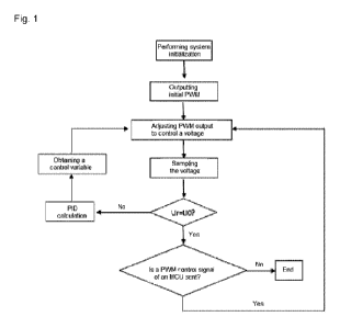
Si: performing system initialization of the software algorithm;
S2: inputting initial PWM;
S3: adjusting PWM output to perform voltage control;
S4: sampling the output voltage of the hardware circuit of the hot surface
igniter;
S5: determining whether a sampled voltage Ur is equal to an expected voltage
UO: if so, entering
S6, and if not, entering S7;
2
Date Recue/Date Received 2022-03-17
CA 03154924 2022-03-17
S6: determining whether a PWM control signal of an MCU is sent: if so,
returning to S3, and if
not, ending; and
S7: performing PID calculation to obtain a control variable, and returning to
S3.
Further, in step III, a constant power is outputted to control the temperature
value of the hot
surface igniter in the t1, t2 and/or tn time period, including the following
processes:
Si: performing system initialization;
S2: inputting initial PWM;
S3: adjusting PWM output to perform voltage control;
S4: sampling the output voltage of the hardware circuit of the hot surface
igniter;
S5: sampling a resistance value or a current of the hot surface igniter;
S6: calculating power according to a formula P=U2/R or P=UI;
S7: determining whether a voltage Pr in S6 is equal to an expected voltage PO:
if so, entering
S8, and if not, entering S9;
S8: determining whether a PWM control signal of an MCU is sent: if so,
returning to S3, and if
not, ending; and
S9: performing PID calculation to obtain a control variable, and returning to
S3.
Preferably, after sampling a resistance value or a current of the hot surface
igniter in S5, preform
the resistance value determination or the current determination in S10, if the
resistance value or the
current is normal, enter S6, and if the resistance value or the current is
anomalous, end.
Preferably, the working time of the hot surface igniter is divided into t1,
t2, ..., and tn time periods
according to a slope of the working time-temperature change curve, and time
intervals corresponding
to segments with consistent or similar continuous slopes of the working time-
temperature change
curve are set as one time period.
Beneficial effect:
The disclosure provides a control strategy for a hot surface igniter. Through
the control strategy
of the disclosure, the ignition time of the hot surface igniter may be easily
controlled. The
requirements of the user of igniting in a short time are satisfied.
3
Date Recue/Date Received 2022-03-17
CA 03154924 2022-03-17
In addition, the control strategy for the hot surface igniter of the
disclosure is performed within
the rated voltage of the hot surface igniter, and will not affect the service
life of the hot surface igniter
at all. In addition, there is no need to replace the power supply of the hot
surface igniter, so that the
application cost of the hot surface igniter is controlled and it is more
acceptable for the customers.
An application range of the hot surface igniter is improved, so that the same
hot surface igniter
may be used in application scenarios with different temperatures and time
requirements, such as a
stove, a water heater, and an engine, etc. In addition, this type of the hot
surface igniter is
independently researched and developed by the company, and until now, no
company in the world
has used or disclosed it. A competitive force of the company is improved, and
it also makes a great
contribution to the customers.
Brief Description of the Drawinds
Fig. 1 is a voltage control flow diagram in any time period;
Fig. 2 is a power control flow diagram in any time period;
Fig. 3 is a working time-temperature change curve of a hot surface igniter of
domestic or
commercial gas cooker and water heater in Embodiment I; and
Fig. 4 to Fig. 6 are hardware circuit diagrams.
Detailed Description of the Embodiments
The disclosure is described below through embodiments shown in the drawings,
but the
disclosure is not limited to the described implementation modes, any
improvements or replacements
in the basic spirit of this embodiment still belong to a scope of protection
claimed by the claims:
Embodiment: As shown in Figs. 1-6, this embodiment provides a control strategy
for an ignition
temperature of a hot surface igniter in working time, and it is divided into
constant voltage control,
constant power control, variable voltage control, variable power control, and
variable voltage and
variable power mixed control.
Herein, for application scenarios in which a temperature is required to be
linearly changed in
working time, the working temperature of the hot surface igniter may be
controlled in a constant
power mode or a constant voltage mode during the whole working time.
For application scenarios in which a temperature is nonlinearly changed in
working time, the
working temperature of the hot surface igniter may be controlled in a variable
voltage control mode,
4
Date Recue/Date Received 2022-03-17
CA 03154924 2022-03-17
a variable power control mode or a variable voltage and variable power mixed
control mode,
specifically including the following steps:
step I, obtaining a working time-temperature change curve that meets
requirements according
to product characteristics and application scenarios of the hot surface
igniter;
step II, dividing the working time of the hot surface igniter in step I into
t1, t2, ..., and tn time
periods; and
step III, in each time period, controlling, by the software algorithm, the
output voltage or output
power of the hardware circuit to make the hot surface igniter reach a
temperature value in the time
period.
Herein the working time-temperature change curve is set according to related
factors such as
product characteristics of the hot surface igniter itself, input power,
application scenarios, and
customer demands , and is also obtained by repeated experimental verification
and related
calculations according to these related factors. A size of a time scale of t1,
t2, ..., and tn is obtained
through the experimental verification and related calculations.
If the variable voltage control is used in step III, then the working time of
the hot surface igniter
is divided into t1, t2, ..., and tn time periods, so that the temperature in
any one time period may be
controlled by the same voltage, but the temperatures in different time periods
may be controlled by
the different voltages. Based on the temperature curve of each working time
period of the hot surface
igniter, an expected voltage UO in this time period is obtained, and a
hardware circuit is controlled
by a software algorithm so that a voltage in this time period is Ur=UO, and
the hot surface igniter
reaches the expected temperature. In another working time period, the hardware
circuit is controlled
by the software algorithm to make the voltage in this time period equal to the
expected voltage in
this time period, so that the hot surface igniter reaches the expected
temperature in this time period.
As shown in Fig. 1, a voltage control process in any one time period is as
follows:
Si: performing system initialization of the software algorithm;
S2: inputting initial PWM;
S3: adjusting PWM output to perform voltage control;
S4: sampling the output voltage of the hardware circuit of the hot surface
igniter;
S5: determining whether a sampled voltage Ur is equal to an expected voltage
UO: if so, entering
S6, and if not, entering S7;
Date Recue/Date Received 2022-03-17
CA 03154924 2022-03-17
S6: determining whether a PWM control signal of an MCU is sent: if so,
returning to S3, and if
not, ending; and
S7: performing PID calculation to obtain a control variable, and returning to
S3.
If the variable power control is used in step III, then the working time of
the hot surface igniter is
divided into t1, t2, ..., and tn time periods, so that the temperature in any
one time period may be
controlled by the same power, but the temperatures in different time periods
may be controlled by
different powers. According to the temperature curve of each working time
period of the hot surface
igniter, an expected power PO in this time period is obtained, and the
hardware circuit is controlled
by the software algorithm so that a power in this time period is Pr=PO, and
the hot surface igniter
reaches an expected temperature. In another working time period, the hardware
circuit is controlled
by the software algorithm to make the power in this time period equal to the
expected power in this
time period, so that the hot surface igniter reaches the expected temperature
in this time period.
As shown in Fig. 2, a power control process in any one time period is as
follows:
Si: performing system initialization;
S2: inputting initial PWM;
S3: adjusting PWM output to perform voltage control;
S4: sampling the output voltage of the hardware circuit of the hot surface
igniter;
S5: sampling a resistance value or a current of the hot surface igniter;
S6: calculating power according to a formula P=U2/R or P=UI;
S7: determining whether a voltage Pr in S6 is equal to an expected voltage PO:
if so, entering
S8, and if not, entering S9;
S8: determining whether a PWM control signal of an MCU is sent: if so,
returning to S3, and if
not, ending; and
S9: performing PID calculation to obtain a control variable, and returning to
S3.
As another implementation mode of this embodiment, after sampling a resistance
value or a
current of the hot surface igniter in S5, perform the resistance value
determination or perform the
current determination in S10, if the resistance value or the current is
normal, enter S6, and if the
resistance value or the current is anomalous, end.
6
Date Recue/Date Received 2022-03-17
CA 03154924 2022-03-17
If the variable voltage and variable power mixed control is used in step III,
then the working time
of the hot surface igniter is divided into t1, t2, ..., and tn time periods,
and different time periods are
selected to use the voltage control or power control, respectively. Herein a
selection standard is
based on efficiency, i.e. to choose the control mode that will reach the
expected temperature in a
shorter time. In each corresponding working time period, the voltage control
or power control is used
respectively, and a control flow is as above.
As one of selection modes, the working time period may be divided according to
a slope of the
working time-temperature change curve. For example, if the slope of a time
interval is continuously
consistent or does not change rapid, the time interval is set as a working
time period tn.
An example of applying the control strategy in this embodiment to an actual
using process of
the hot surface igniter is provided below. The application examples in
following two fields are only
used to illustrate an implementation process of the disclosure, and the
implementation process of
the disclosure is not limited to be only applied in these two fields.
Example 1: Application in domestic or commercial gas stove and water heater
While the gas stove or the water heater is used, long time from ignition to
ignition success may
arouse an anxious mood of people, and the time is generally best to be
controlled within 5 seconds.
However, in application scenarios in which there is no time requirement, in
order to guarantee
non-over-temperature and service life of the hot surface igniter, a control
mode of constant voltage
or constant power is generally used to slowly heat up the igniter.
In combination with the above, if the hot surface igniter is needed to be well
used in the gas
cooker or the water heater, two contradiction aspects must be balanced.
Therefore, the three types
of the control strategies including the variable voltage control, the variable
power control, and the
variable voltage and variable power mixed control in this embodiment may be
used to guarantee the
service life of the hot surface igniter and shorten the ignition time of the
gas cooker and the water
heater.
Fig. 3 is a working time-temperature change curve of domestic or commercial
gas cooker and
water heater. It uses a dedicated temperature measurement laboratory, uses a
high-precision
temperature measurement instrument, and monitors a working curve of the
igniter in real time
through a computer. Technical parameters are adjusted for purposes of the
different application
requirements, to obtain a best time scale.
Taking the working curve of the heating hot surface igniter in Fig. 3 as an
example, if the control
7
Date Recue/Date Received 2022-03-17
CA 03154924 2022-03-17
strategy of this embodiment is adopted, the hot surface igniter may present a
temperature A curve,
and may reach the highest temperature between t3 and t4 to ignite a
combustible gas. If common
voltage or power control is used, the hot surface igniter may show a
temperature B curve, the
combustible gas may be ignited at the time point of t10, or it may also show a
temperature C curve,
it is damaged at the time point of t5 to t6 due to over-temperature.
Applying the ignition strategy of this embodiment guarantees not only the
achievement of the
ignition in a short time, but also the using safety and service life of the
hot surface igniter.
For an application on an engine preheating system, a requirement for time is
not high, but a
requirement for power or temperature is high. To this end, the constant
voltage or constant power
control may be used according to the actual application.
In addition, in Figs. 4-6, circuit diagrams of hardware control of the hot
surface igniter of this
embodiment is also provided. Certainly, these circuit diagrams are only for
better explaining the
disclosure, and should not be understood as limitation to the disclosure.
Herein a circuit diagram including MCU is shown in Fig. 4. The MCU has two
routes of output,
one route is control signal output, and the other route is voltage acquisition
output.
A control signal output terminal is connected to a base of a triode Q1 after
being connected with
a resistor R4, an emitter of the triode is grounded, a collector is connected
to a resistor R2, and a
resistor R5 is connected between the base of the triode Q1 and a transmitter.
The other end of the
resistor R2 is connected with a grid of a field effect tube Si, a source of
the field effect tube Si is
connected with a power supply DC, a drain of the field effect tube is
connected with a positive
electrode of the hot surface igniter, and the negative electrode of the hot
surface igniter is grounded.
A voltage stabilizing diode D1 is also connected between the grid and the
source of the field effect
tube Si. A positive electrode of the voltage stabilizing diode D1 is connected
with the source of the
field effect tube Si, and a negative electrode is connected with the grid of
the field effect tube Si,
and a resistor R1 is also connected between the grid and the source of the
field effect triode Si. A
voltage acquisition output terminal is connected to a resistor R3 after being
connected with a resistor
R7, and the resistor R3 is connected to the negative electrode of the hot
surface igniter. In addition,
a branch connection resistor R6 is installed between R7 and R3, the R6 is
grounded, and a branch
connection capacitor C1 is installed between the MCU and R7, and the C1 is
grounded. The voltage
acquisition and signal control of the hot surface igniter may be achieved
through the hardware circuit
in Fig. 4. The variable voltage or constant voltage control may be achieved.
Fig. 5 shows another circuit diagram, including PLC. The PLC has three routes
of output, one
8
Date Recue/Date Received 2022-03-17
CA 03154924 2022-03-17
route is control signal output, one route is voltage acquisition output, and
the other route is current
acquisition output.
A control signal output terminal is connected to a base of a triode Q1 after
being connected with
a resistor R3, an emitter of the triode is grounded, and a resistor R5 is
connected between the base
of the triode Q1 and a transmitter. A collector of the triode is connected to
a negative electrode of a
diode D1, a positive electrode of the D1 is connected to a power supply VCC,
an electromagnetic
switch K1 is connected between the positive electrode and the negative
electrode of the diode D1,
one end of the electromagnetic switch K1 is connected to a positive electrode
of the hot surface
igniter, and the other end is connected to a negative electrode of the hot
surface igniter, and the
negative electrode of the hot surface igniter is also grounded through a
constantan wire. A voltage
acquisition output terminal is connected to a resistor R1 after being
connected with a resistor R6,
the resistor R1 is connected to the positive electrode of the hot surface
igniter, a branch connection
resistor R2 is installed between the resistors R6 and R1, and the resistor R2
is connected with the
negative electrode of the hot surface igniter. A branch connection capacitor
Cl is installed between
the PLC and R6, and the Cl is grounded. A current acquisition output terminal
is connected to the
negative electrode of the hot surface igniter after being connected with a
resistor R4. The signal
control, voltage acquisition and current acquisition of the hot surface
igniter may be achieved through
the hardware circuit in Fig. 5. The acquisition of power may be achieved
through the acquisition of
the voltage and current. Further, the constant voltage control, constant power
control, variable
voltage control, variable power control or variable voltage and variable power
mixed control of the
hot surface igniter is achieved.
Fig. 6 shows another circuit diagram, including a computer connected with an
industrial control
module, and the industrial control module has three routes of output, one
route is control signal
output, one route is voltage acquisition output, and the last route is
resistance acquisition output.
A control signal output terminal is connected to a base of a triode Q2 after
being connected with
a resistor R7, an emitter of the triode is grounded, a collector is connected
to a resistor R5, and a
resistor R8 is connected between the base of the triode Q2 and a transmitter.
The other end of the
resistor R5 is connected with a base of a triode Q1, an emitter of the triode
Q1 is connected with a
power supply DC, a collector is connected with a positive electrode of the hot
surface igniter, and
the negative electrode of the hot surface igniter is grounded. A resistor R4
is also connected between
the emitter and the base of the triode Ql, and the collector of the triode Q1
is also grounded through
a diode D3. A voltage acquisition output terminal is connected to a resistor
R6 after being connected
with a resistor R10, and the resistor R6 is connected to a positive electrode
of the hot surface igniter.
9
Date Recue/Date Received 2022-03-17
CA 03154924 2022-03-17
In addition, a branch connection resistor R9 is installed between R10 and R6,
the resistor R9 is
grounded, and a branch connection capacitor C2 is installed between the
industrial control module
and R10, and the C2 is grounded. A resistance value acquisition output
terminal is connected to the
positive electrode of the hot surface igniter after being sequentially
connected with the resistors R1
and R3. A branch connection capacitor C1 is installed between the industrial
control module and the
resistor R1, and grounded. Another branch connection diode D1 is installed
between the industrial
control module and the resistor R1, and grounded. A branch connector resistor
R2 and a diode D2
are installed between the resistors R1 and R3, and connected with a power
supply VCC. The signal
control, voltage acquisition and resistance value acquisition of the hot
surface igniter may be
achieved through the hardware circuit in Fig. 6. The acquisition of power may
be achieved through
the acquisition of the voltage and resistance. Furthermore, the constant
voltage control, constant
power control, variable voltage control, variable power control, or variable
voltage and variable power
mixed control of the hot surface igniter is achieved.
Date Recue/Date Received 2022-03-17