Note: Descriptions are shown in the official language in which they were submitted.
Attorney Docket No. 012263
RELOADABLE CONTAINERIZED SYSTEM FOR WET AND DRY
PROPPANTS AND METHODS OF MAKING AND USING SAME
CROSS-REFERENCE TO RELATED APPLICATIONS
[0001] This application claims priority to U.S. Provisional Patent
Application, Serial No.
63/175,450, titled "Systems and Methods for Reloading Material Storage
Containers," and filed
April 15, 2021. The disclosure of the '450 Provisional Application is
incorporated by reference
herein in its entirety.
BACKGROUND
[0002] During completion operations for oil and gas wells, hydraulic
fracturing operations
are often utilized to increase the production from the well. During such
hydraulic fracturing
operations, a hydraulic fracturing fluid comprising a mixture of fluids,
chemicals, and proppants
is blended and pumped into the well bore. The particular composition of a
hydraulic fracturing
fluid can vary from well to well. Further, because of the highly abrasive
nature of the fracturing
fluid, the fracturing fluid is typically blended at the well site in a blender
rather than being pumped
from offsite. Accordingly, the necessary components for the fracturing fluid
must be present at the
well site. Storing these components, and particularly the wet or dry
proppants, presents unique
challenges to ensure that the fracturing operations are able to proceed
efficiently and cost-
effectively.
SUMMARY
[0003] The following presents a simplified summary of the disclosure in
order to provide
a basic understanding of some aspects of the disclosure. This summary is not
an extensive
overview of the disclosure. It is not intended to identify critical elements
of the disclosure or to
delineate the scope of the disclosure. Its sole purpose is to present some
concepts of the disclosure
in a simplified form as a prelude to the more detailed description that is
presented elsewhere herein.
[0004] In some aspects, the techniques described herein relate to a
method for reloading a
container with proppant. A method comprises providing a system for reloading
containers. The
system includes a transloader having a conveyer belt and a discharge device,
and a reloading
1
Date Recue/Date Received 2022-04-13
Attorney Docket No. 012263
system. The reloading system comprises a bulk material storage bin having a
proppant receiving
area, a proppant dispensing device having an expandable loading tube, and a
gate. The system
further includes a reloader having a loading bay including a load cell. The
method includes
disposing the proppant onto the conveyer belt and causing the discharge device
to discharge the
proppant into the bulk material storage bin. The method comprises situating
the container in the
loading bay atop the load cell. The method includes opening the gate and
causing the expandable
loading tube to expand to deliver the proppant from the bulk material storage
bin into the container.
The method comprises removing the container from the loading bay after a
weight of the container
reaches a predetermined weight.
[0005] In another embodiment, a system for reloading a container with
proppant comprises
a transloader having a conveyer belt and a discharge device. The system
includes a reloading
system comprising a bulk material storage bin having a proppant receiving
area, a funnel having
an expandable loading tube, and a gate for controlling flow of the proppant
from the funnel into
the container. The system comprises a reloader comprising a loading bay
including a load cell and
the container disposed on the load cell.
[0006] In yet another embodiment, a method for reloading a container with
proppant
comprises providing a system for reloading containers. The system comprises a
transloader having
a conveyer belt and a discharge device, and a reloading system. The reloading
system includes a
bulk material storage bin having a proppant receiving area, a proppant
dispensing device having
an expandable loading tube, and a gate. The system further includes a reloader
comprising a
loading bay including a load cell. The method includes causing the discharge
device to discharge
the proppant into the bulk material storage bin, situating the container in
the loading bay, and
causing the expandable loading tube to expand to deliver the proppant from the
bulk material
storage bin into the container.
BRIEF DESCRIPTION OF THE DRAWINGS
[0007] Illustrative embodiments of the disclosure are described in detail
below with
reference to the attached drawings.
[0008] FIG. 1 is a schematic illustration of a system for reloading
storage containers
according to embodiments of the disclosure.
2
Date Recue/Date Received 2022-04-13
Attorney Docket No. 012263
[0009] FIG. 2A illustrates a bulk material storage bin of the system of
FIG. 1.
[00010] FIG. 2B is a bottom view of the bulk material storage bin of FIG. 2A.
[00011] FIG. 2C is a front view of a funnel of the bulk material storage bin
of FIG. 2A.
[00012] FIG. 3 is a perspective view of a reloader of the system of FIG. 1
according to
embodiments of the disclosure.
[00013] FIG. 4 illustrates a front view of a bulk material storage bin as
supported by a
reloader according to embodiments of the disclosure.
[00014] FIGs. 5A and 5B are side views of the bulk material storage bin as
supported by
the reloader according to embodiments of the disclosure.
[00015] FIG. 6 is a schematic of an automated control system for operating the
bulk material
storage bin, a transloader, and a reloader of the system for reloading storage
containers of FIG. 1,
according to embodiments of the disclosure.
[00016] FIG. 7 is a flow diagram of a method of operating a reloading system
according to
embodiments of the disclosure.
DETAILED DESCRIPTION
[00017] Many different storage systems exist for storing proppants for
hydraulic fracturing
operations. In one example, a silo-style system incorporates a plurality of
silos that are transported
to a well site where the silos are erected and filled with proppant. The
proppant may be delivered
to the well site via a truck and trailer, and then conveyed or pneumatically
transferred the silos for
storage. When the time comes to hydraulically fracture the well, the proppant
is dispensed from
the silo(s) onto a conveyor or gravity fed and into the blender where it is
mixed with water and
other chemicals before being sent downhole. The silo systems are beneficial
because they offer
higher payload compared to other containerized systems. However, the silo
systems are expensive,
loading systems can be unreliable, and may require specialty equipment in
order to erect and/or
operate the system.
[00018] Containerized storage systems utilize smaller containers to transport
and store
proppant. Such systems are less expensive and can be safer than silo systems
when it comes to
reducing silica dust, for example. Additionally, containerized systems are
more versatile, as the
containers can be more easily moved between locations, and can even be
directly coupled to the
blender preventing the need for proppant conveyors (and therefore reducing
silica dust). However,
3
Date Recue/Date Received 2022-04-13
Attorney Docket No. 012263
the containers are not able to hold as much proppant with holding capacities
ranging from about
12 tons of proppant per box to around 25 tons of proppant per box.
Additionally, containers often
require specialized trailers for transport and/or discharge of proppant at the
well site. In order to
provide the required amount of proppant for a fracking operation, many
delivery trucks may be
required to deliver numerous containers, sometimes over 100 boxes, increasing
the possibility for
accidents. Once on location, the storage area for the boxes may be 10,000
square feet or more.
[00019] Systems and methods for utilizing a reloadable containerized storage
system for a
hydraulic fracturing operation are described herein. According to embodiments
of the disclosure,
a containerized system utilizes a plurality of containers known to the
industry for storing proppant.
A reloading system allows the containers to be reloaded such that fewer
containers are required to
be stored at the wellsite. Transportation of proppant to the reloader can be
accomplished with any
style of bulk material trailer including but not limited to grain style and
pneumatic style trailers.
Payloads with such trailers can be higher than traditional containerized sand
trailers reducing the
number of loads to location and environmental impact. Thus, the system blends
the efficiencies of
silo systems with the reliability and versatility of box systems.
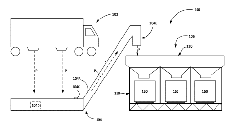
[00020] Referring to FIG. 1, a system 100 for reloading proppant containers
includes a
delivery vehicle 102, a transloader 104, and a reloading system 106. The
reloading system 106,
described in detail below, generally includes a bulk material storage bin 110
and a reloader 130.
In a highly generalized summary, proppant P for use in hydraulic fracturing
operations is delivered
to a wellsite via the delivery vehicle 102 and offloaded onto the transloader
104 which deposits
the proppant P into the reloading system 106 for reloading containerized
proppant units (or simply
"containers") 150. The flow of proppant P from the vehicle 102 to the
reloading system 106 is
represented by the arrows in FIG. 1. One or more components of the system 100
may be in data
communication with and controllable by an automated control system 200 (FIG.
6), described in
more detail herein.
[00021] The proppant P may be dry proppant DP or wet proppant WP. The moisture
content
of the proppant P may impact the flow of the proppant P from the bulk material
storage bin 110
into the container 150 (e.g., all other things being equal, wet proppant WP
may flow from the bulk
material storage bin 110 into the container 150 at a slower rate than dry
proppant DP, and wet
proppant WP may have a higher likelihood of getting jammed in the bulk
material storage bin 110
relative to dry proppant DP). In embodiments, certain features and workings of
the system 100
4
Date Recue/Date Received 2022-04-13
Attorney Docket No. 012263
may be adaptively modified based on the moisture content of the proppant P. In
other
embodiments, one reloading system 100 may be configured exclusively or
primarily for dry
proppant DP and another reloading system 100 may be configured exclusively or
primarily for wet
proppant WP, in line with the teachings of the present disclosure. The term
"wet proppant," as
used herein, refers to proppant P with a moisture content greater than or
equal to one percent. The
moisture content may be measured using Equation 1 below or using other
suitable methods known
in the art or developed in the future.
Equation 1:
moisture content of proppant
(weight of moist proppant ¨ weight of dry proppant)
. ____________________________________________________________________
weight of dry proppant
[00022] For instance, if the weight of moist proppant is 102g and the weight
of dry proppant
is 90g, the moisture content of this proppant P is 0.133 or 13.3%. As such,
this proppant P may be
characterized as wet proppant WP.
[00023] The delivery vehicle 102 can be any vehicle configured to deliver
proppant P to the
wellsite, such as a grain trailer, pneumatic trailer, and the like. Because
the delivery vehicle 102
does not need to be specially configured, any available delivery vehicle, or
multiple types of
delivery vehicles, may deliver proppant to the wellsite. This is beneficial
because the operator is
not limited by the availability of specific types of trailers or drivers for
such trailers. Typically,
however, the trailer will have a hopper bottom designed for offloading
material at the well site.
[00024] The transloader 104 may have a conveyer belt 104A, a discharging
device 104B, a
moisture content reader 104C, and a controller 104D.
[00025] The transloader 104 may be any conveyor-type known to those of skill
in the art,
for example, an RBT-style transloader, mobile conveyor or auger, or any other
conveying
mechanism. Regardless of the type, the transloader 104 receives the proppant
material P from the
delivery vehicle 102 and, via the conveyer belt 104A and discharging device
104B thereof,
conveys the proppant material P to the reloading system 106. Specifically, the
conveyer belt 104A
may convey the proppant material P to the discharging device 104B and the
discharging device
104B may convey the proppant material P to the bulk material storage bin 110
of the reloading
Date Recue/Date Received 2022-04-13
Attorney Docket No. 012263
system 106. The proppant P may ultimately be conveyed from the bulk material
storage bin 110
of the reloading system 106 to the container 150 as set forth herein.
[00026] The discharging device 104B may be located at a distal end of the
transloader 104
and may optionally be selectively movable in order to discharge the proppant P
into a particular
area of the bulk material storage bin 110. The discharging device 104B is
discussed in more detail
with reference to FIG. 4.
[00027] The moisture content reader 104C may be located on the conveyer belt
104A of the
transloader 104 and/or elsewhere (e.g., on the discharging device 104B, within
the bulk material
storage bin 110, et cetera). The moisture content reader 104C may be any
suitable sensor now
known or developed in the future that allows for the moisture of the proppant
P to be determined,
e.g., so as to distinguish between wet proppant WP and dry proppant DP. In
embodiments, the
readings of the moisture sensor 104C may be fed to the controller 104D in a
wired or wireless
manner. The moisture content reader 104C may, in embodiments, comprise a
grouping of moisture
sensors that are placed on the transloader 104 and/or reloading device 106.
[00028] The controller 104D may control the operation of the transloader 104
based, e.g.,
on input from the automated control system 200. For example, the controller
104D may control
the operation of the conveyer belt 104A (e.g., start, stop, speed up, or slow
down the belt 104A)
and/or control the operation of the discharging device 104B (e.g., cause the
discharging device
104B to convey proppant P to a particular area of the bulk material storage
bin 110) based on input
from the automated control system 200. The controller 104D may, in
embodiments, use the
readings from the moisture content reader 104C to identify the proppant P as
one of wet proppant
WP and dry proppant DP and communicate same to the automated control system
200. In other
embodiments, the controller 104D may communicate the reading of the moisture
content reader
104C to the automated control system 200 and the automated control system 200
may determine
whether the proppant P is to be categorized as dry proppant DP or wet proppant
WP.
[00029] As noted above, the reloading system 106 broadly includes a bulk
material storage
bin 110 and a reloader 130. The bulk material storage bin 110 is a storage
vessel for holding and
dispensing proppant material P to the containers 150, and may be configured to
temporarily store
at least 10 tons of proppant. In embodiments, the bulk material storage bin
110 may hold 20, 30,
40, 50, 60, 70, 80, 90, or 100 or more tons of proppant.
6
Date Recue/Date Received 2022-04-13
Attorney Docket No. 012263
[00030] Referring now to FIGs. 2A and 2B, the bulk material storage bin 110
includes a
proppant receiving area 110A and a proppant dispensing area 110B. The proppant
dispensing area
110B may be proximate the reloader 130 relative to the proppant receiving area
110A. Proppant P
may be delivered by the transloder 104, and specifically the discharging
device 104B thereof, to
the proppant receiving area 110A of the bulk material storage bin 110. The
proppant P may flow
from the proppant receiving area 110A down into the proppant dispensing area
110B and into one
or more of the containers 150. The flow of the proppant P from the bulk
material storage bin 110
into the containers 150 may be due to gravity, and as discussed herein, may be
aided by vibration
devices and the like as appropriate. The surfaces of the bulk material storage
bin 110 may be
configured to ensure that the proppant P flows from the bulk material storage
bin 110 into the
containers 150 at an appropriate rate such that the containers 150 are filled
quickly and efficiently
without spillage.
[00031] The proppant dispensing area 110B may comprise one or more funnels (or
proppant
dispensing devices) 111. While four funnels 111 are shown in FIG. 2A, it shall
be understood by
those of skill in the art that the bulk material storage bin 110 may have
fewer than four (e.g., one
two, or three ¨ such as shown in FIG. 1) or greater than four (e.g., five or
more) funnels 111. Each
funnel 111 defines an opening 112 in the bottom of the bulk material storage
bin 110 through
which proppant P is permitted to flow.
[00032] A gate 116 covers each of the openings 112. Each gate 116 may be
configured as a
knife gate, butterfly gate, or the like. The gate 116 may be coupled to a
regulator 118 (FIG. 2B)
that is operable to open and close the gate 116 to control the flow of
proppant P from the bulk
material storage bin 110. The regulator 118 may be controlled hydraulically,
pneumatically,
electrically, or otherwise as is known to those of skill in the art. As
described below, the regulator
118 may be in communication with the automated control system 200 (FIG. 6)
that controls the
regulator 118, and therefore, the position of the gate 116.
[00033] A loading tube 120 may be secured around the opening 112 of each
funnel 111, and
may be designed to expand and contract to deliver proppant P from the bulk
material storage bin
110. A distal end 120D of the loading tube 120 may include a diffuser 122,
such as a witch's hat,
to aid in spreading the discharged proppant P. The diffuser 122 may facilitate
the even spread of
the discharged proppant P into the container 150. In embodiments, the
expansion and contraction
of the loading tube 120 may be controlled via the automated control system
200.
7
Date Recue/Date Received 2022-04-13
Attorney Docket No. 012263
[00034] As shown in FIG. 2A, the bulk material storage bin 110, and
specifically the
proppant receiving area 110A thereof, may optionally be equipped with one or
more partitions or
dividers 114 separating the vessel 110 into sections 115A, 115B, and 115C.
Each section 115A,
115B, and 115C may have associated therewith a solitary funnel 111 or a
grouping of funnels 111.
The sections 115A, 115B, and 115C may receive different proppant materials P
for use in the
fracking fluid (e.g., section 115A and section 115B may receive proppant P
having different
moisture contents). Two partitions 114 are disclosed in the figures; however,
it will be understood
by those of skill in the art that a single partition 114, or more than two
partitions 114, may be
situated within the bulk material storage bin 110 to create sections for
receiving different types of
proppant materials.
[00035] The dividers 114, where employed, may be removable or may be fixed.
Where the
dividers 114 are removable, the bulk material storage bin 110 may be divided
into one or more
sections in line with the requirements of the job. For example, a divider 114
may be employed to
create a section for housing and dispensing dry proppant DP and another
section for housing and
dispensing wet proppant WP. Dividers 114 may likewise be used to guide the
proppant P into a
particular container 150. As such, different sections of the bulk material
storage bin 110 may have
the same type of proppant P.
[00036] The bulk material storage bin 110 may comprise one or more measurement
devices
113A and one or more actuating devices 113B. The measurement devices 113A and
the actuating
devices 113B may be situated in the proppant receiving area 110A, the proppant
dispensing area
110B (e.g., proximate the gate 116), and/or at another suitable location
inside the bulk material
storage bin 110.
[00037] In embodiments, at least one measurement device 113A and at least one
actuating
device 113B may be associated with each funnel 111. Thus, while FIG. 2A shows
one
measurement device 113A and one actuating device 113B associated with each
funnel 111, in
embodiments, two or a different number of measurement devices 113A and two or
a different
number of actuating devices 113B may be associated with each funnel 111. In
embodiments, one
funnel 111 may have a different number of measurement devices 113A or
actuating devices 113B
associated with it relative to another funnel 111. In some embodiments, the
actuating devices 113B
may mounted at multiple locations within the system 100 to aid in the flow of
proppant P. In
8
Date Recue/Date Received 2022-04-13
Attorney Docket No. 012263
embodiments, one or more measurement devices 113A and/or actuating devices
113B may be
omitted.
[00038] The measurement device 113A, in embodiments, is a sensing device that
allows for
the determination of a property of the proppant P associated with a particular
funnel 111 and/or a
section (e.g., section 115A) of the bulk material storage bin 110 associated
with that funnel 111.
The measurement device 113A may, e.g., be a contact and/or non-contact height
sensor, a volume-
determining device, or other appropriate device for determining at least one
property of the
proppant P associated with a particular funnel 111 or section. For example,
the measurement
device 113A may be a mechanical height sensor, a radar level measurement
device, an ultrasonic
level sensor, a LIDAR volume sensor, et cetera. The measurement device 113A
may, for instance,
allow for a height and/or volume of proppant P in the funnel 111 to be
determined, so as to ensure
that the area of the material storage bin 110 associated with the measurement
device 113A is not
overfull with proppant P or has an inadequate amount of proppant P.
[00039] The actuating device 113B may be any device configured to facilitate
the flow of
proppant P from the material storage bin 110, e.g., the funnel 111 thereof,
into the container 150.
The actuating device 113B may, e.g., be a pneumatic vibrator device, an
electrical vibrator device,
or other suitable device configured to urge the proppant P from the bulk
material storage bin 110
into the container 150. The actuating device 113B may be controlled by the
automated control
system 200. The actuating device 113B may further be actuated manually by an
operator as
desired.
[00040] The bulk material storage bin 110 may include a controller 113C, which
may be
housed within the bulk material storage bin 110 or at a suitable location
outside the bulk material
storage bin 110. The controller 113C may be in data communication with the
automated control
system 200, and may interact with the measurement device 113A, the actuating
device 113B,
and/or the regulator 118. For example, the controller 113C may convey
measurements taken by
the measurement device 113A to the automated control system 200 and control
the actuating
device 113B and/or the gate 116 based on directions provided by the automated
control system
200. For instance, where the measurements from the measurement device 113A
indicate that the
proppant P is not flowing through the funnel 111 into the container 150 or is
flowing downstream
at too slow a rate (e.g., at less than 10001bs per 30 seconds), the automated
control system 200
9
Date Recue/Date Received 2022-04-13
Attorney Docket No. 012263
may cause the controller 113C to activate the actuation device 113B to speed
up the flow of
proppant P into the container 150 and/or cause the regulator 118 to more fully
open the gate 116.
[00041] The automated control system 200 may further control the operation of
the
transloader 104 based on input from the measurement device 113A. For instance,
where the
measurement device 113A indicates that a particular section (e.g., section
115A) is nearing
capacity, the automated control system 200 may cause the discharging device
104B of the
transloader 104 to discharge proppant P to a different section (e.g., section
115B) .
[00042] The automated control system 200 may also regulate the speed of the
transloader
conveyer belt 104A based on the measurements taken by the measurement
device(s) 113A. For
example, where the measurement devices 113A indicate the bulk material storage
bin 110 is
nearing capacity (e.g., the bulk material storage bin 110 is at 85% capacity),
the automated control
system 200 may, in communication with the transloader controller 104D, reduce
the speed of the
conveyer belt 104A and generate an alarm (e.g., an audible alarm, a visual
alarm, an electronic
communication delivered to a mobile device of an operator, et cetera) so that
operation of the
system 100 may be evaluated. The automated control system 200 may further halt
the conveyer
belt 104A where the measurements from the measurement devices 113A indicate
the bulk material
storage bin 110 is at capacity.
[00043] FIG. 2C shows an example funnel 111 in more detail. Each funnel 111
may be
symmetrical (e.g., a left half of the funnel 111 may be a mirror image of the
right half thereof).
Alternately, the shape of the funnel 111 may be irregular and may be
configured in line with the
particular application. Not all funnels 111 need to be identical.
[00044] In embodiments, each funnel 111 may have at least one angled wall
section 111A
and one angled wall section 111B. The angled wall section 111A may make an
exterior angle a
with a horizontal plane H and the angled wall section 111B may make an
exterior angle p with the
horizontal plane H. The angle a may, in embodiments, be disparate from the
angle I.
[00045] While not required, the angles a and p of the wall sections 111A and
111B,
respectively, may be adjustable. For example, where the proppant P is
determined to be dry
proppant DP, at least one of the angle a and the angle p may be set to about
thirty degrees (30 ) as
these angles a and/or p may allow for the dry proppant DP to freely flow from
the material storage
bin 110 to the container 150 at the appropriate rate. Alternately, where the
proppant P is determined
to be wet proppant WP, one or both of the angles a and p may be increased,
e.g., to about thirty-
Date Recue/Date Received 2022-04-13
Attorney Docket No. 012263
five degrees (35 ) or more. The increased slope of the wall sections 111A
and/or 111B may ensure
the wet proppant P travels into the appropriate container 150 at the desired
rate despite the moisture
content of the proppant P.
[00046] The wall sections 111A and/or 111B, and therefore the angles a and/or
13, may be
adjusted manually. Alternately, the wall sections 111A and/or 111B may be
motorized and a user
may set the angles a and/or 0 or the automated control system 200 may
automatically set these
angles based, e.g., on the moisture content of the proppant P and its flow
rate into the container
150. In other embodiments still, the wall sections 111A and/or 11 !B may be
fixed. In these
embodiments, a bulk material storage bin 110 may be created for dry proppant
DP and a separate
bulk material storage system 110 may be created for wet proppant WP such that
the angles a and/or
13 of the wet proppant material storage system 110 are greater than the angles
a and/or13 of the dry
proppant material system 110. In some embodiments, certain funnels 111 of a
solitary bulk
material storage bin 110 may be designed for wet proppant WP and other funnels
111 of that same
bulk material storage bin 110 may be designed for dry proppant DP.
[00047] Other changes may likewise be made to the system 100 based on whether
the
proppant P is dry proppant DP or wet proppant WP. For example, where the
reloading system 100
is configured for wet proppant WP, the surfaces of one or more components that
are to come into
contact with the wet proppant WP may be coated with anti-friction coatings to
reduce proppant
surface tension and facilitate the flow of the wet proppant WP from the
transloader 104 ultimately
into the container 150.
[00048] Moving on to FIGs. 3-5B, the bulk material storage bin 110 may be
supported on
the reloader 130. The reloader 130 includes a frame 132 defining a receiving
area 134. The frame
132 has a bottom surface 135 that contacts the ground when in use, and a
platform surface or
channel guide 136 for supporting one or more containerized proppant units 150.
A plurality of
partitions 138 may extend between the platform surface 136 and a top of the
frame 132 thereby
defining a plurality of individual reloading (or loading) bays 140A, 140B, and
140C. While three
reloading bays (generally 140) are shown in FIG. 3, it shall be understood
that the reloader 130
may have greater than or fewer than three reloading bays. For example, in FIG.
4, the reloader 130
is shown as having four reloading bays 140A-140D. The reloader 130 may, in
embodiments, have
a solitary reloading bay.
11
Date Recue/Date Received 2022-04-13
Attorney Docket No. 012263
[00049] The bulk material storage bin 110 may be lifted to a position atop the
reloader 130
using any lifting mechanism, including but not limited to a forklift, standard
loader, crane, et
cetera, such that each of the funnels 111 extends generally into (or above) a
respective reloading
bay 140A, 140B, or 140C. The bulk material storage bin 110, in embodiments,
may comprise
outriggers or another anchoring system that couples the bin 110 to the ground
and ensures the bin
110 is not displaced when faced with heavy winds, earthquakes, and the like.
[00050] Each reloading bay 140 may include a load cell 142 configured to
receive a
container 150. The load cell 142 measures a weight of the container 150 in
real time. The load cell
142 may be incorporated into a one-size-fits-all table that can receive any
container 150. In
embodiments, the load cell 142 may be incorporated into an adjustable channel
guide configured
to receive multiple types of containers 150. Regardless, the load cell 142 may
be in operable
communication with the automated control system 200 to control the flow of the
proppant out of
the bulk material storage bin 110 and into the respective container(s) 150
based at least in part on
the weight of the respective container(s) 150. In other words, each load cell
142 measures the
weight of the respective container 150, and the position of the gate 116
(i.e., open, partially open,
or closed) may be automatically controlled based on the weight of the
container 150. Further, the
actuating device 113B may be activated where the measurements from the load
cell 142 indicate
that proppant P is not flowing into the container 150 at a suitable rate.
[00051] Each empty container 150 may be placed into a respective reloading bay
140 using,
for example, a forklift. When the container 150 is placed in the reloading bay
140, a releasing
mechanism (e.g., hooks, magnets, etc.) on the reloader 130 may automatically
open a fill port or
hatch 152 on the container 150 such that the container 150 can receive
proppant from the bulk
material storage bin 110.
[00052] To receive the proppant, the loading tube 120 may expand downwardly
toward the
open fill port in the container 150. As illustrated in FIG. 4, in embodiments,
the loading tube 120
may expand into the container 150 through the open fill port, thereby reducing
the amount of silica
dust created by movement of the proppant. The tube 120 may have a sealing ring
(e.g., rubber,
fiber, etc.) that is configured to form a seal on top of the container 150 to
reduce the amount of
silica dust. The automated control system 200 may control the position of the
loading tube 120
relative to the container 150. In embodiments, the loading tube 120 may
automatically lower when
12
Date Recue/Date Received 2022-04-13
Attorney Docket No. 012263
an empty container 150 (e.g., as determined by the load cell 142) is placed
into a reloading bay
140 and may automatically raise when the container 150 is filled.
[00053] When the load cell 142 determines that the container 150 is full, the
gate 116 may
be closed and a light 155 on the reloader 130 above the respective reloading
bay 140 may be
activated to alert a user that the container 150 is filled and ready to be
removed from the reloader
130. As described in greater below, a display may convey the weight of the box
and may
correspond with a computing device, such as a tablet or computer.
Additionally, as the container
150 is removed from the reloader 130, or prior to the container 150 being
removed from the
reloader 130, the hatch 152 may be automatically closed via the releasing
mechanism. In
embodiments, the weight of the container 150 may be indicated on the container
150, using, e.g.,
an RFID tag, an electronic display meter, and/or using other means.
[00054] The reloader 130 may further include an enclosure 148 that generally
wraps around
the bulk material storage bin 110 and the top of the reloader 130 to control
silica dust generated
by the moving proppant. In embodiments, the enclosure 148 may include a vacuum
unit 149 for
further filtering the air around the reloader 130.
[00055] The reloader 130 may be generally configured as a trailer for easy
transport.
Accordingly, the reloader may include a plurality of wheels 144 and a hitch
146 for connecting to
a vehicle as is known to those in the art. The wheels 144 may be built into
the trailer such that
when the reloader 130 is in the working position, the bottom surface 135
contacts the ground and
the wheels 144 are non-weight bearing. In embodiments, the reloader 130 may be
a skid mounted
unit that is transported on a separate trailer.
[00056] FIG. 4 shows the discharging device 104B of the transloader 104 in
more detail. In
embodiments, the discharging device 104B may have proppant dispensing arms
105A, 105B, and
105C, and so on. While three arms 105A-105C are shown in FIG. 4, one of skill
in the art will
understand that the discharging device 104B may include a greater or fewer
number of arms.
[00057] In some embodiments, the arms 105A-105C may be movable. The movement
of
the arms 115A-115C may be effectuated manually or using automated devices
(e.g., using
actuating devices controlled by the automated control system 200). A proppant
dispensing arm
(e.g., arm 105A) may be moved and resituated to cause that arm to dispense
proppant P into the
appropriate area of the bulk material storage bin 110 (e.g., to cause arm 105A
to dispense proppant
Pinto section 115B instead of section 115A). In embodiments, the slope of the
arms 105A-105A
13
Date Recue/Date Received 2022-04-13
Attorney Docket No. 012263
may be adjustable, e.g., may be increased when the proppant P is wet proppant
WP to facilitate
the transfer of the wet proppant WP from the transloader 104 to the bulk
material storage bin 110.
The distal ends of the arms 105A-105C may be provided with a diffuser or
spreader, e.g., a witch's
hat, to ensure that the proppant P is distributed into the bulk material
storage bin 110, and
specifically the sections 115A-115C thereof, relatively evenly.
[00058] Attention is now directed to FIG. 6, which schematically illustrates
an automated
control system 200 for controlling the reloading system 100. The system 200
includes a computing
device 210 communicatively coupled (e.g., via wires or wirelessly over a
network 205) to the
transloader 104, the bulk material storage bin 110, the reloader 130, and
optionally other
computing devices. The computing device 210 includes a processor 215
communicatively coupled
to a network interface 220, at least one input/output device 225, and memory
230. The processor
215 operates software 235 housed in the memory 230.
[00059] Processor 215 represents one or more digital processors. In some
example
embodiments, the processor 215 may be configured through particularly
configured hardware,
such as an application specific integrated circuit (ASIC), field-programmable
gate array (FPGA),
etc., and/or through execution of software to perform functions in accordance
with the disclosure
herein. Network interface 220 may be implemented as one or both of a wired
network interface
and a wireless network (e.g., Wi-Fi, Internet, Bluetooth, Cellular, etc.)
interface, as is known in
the art.
[00060] The input/output device 225 may include one or more input and/or
output devices
which may be embodied in a single device or multiple devices. The input/output
device 225 may
include a keyboard, a mouse, a stylus pen, buttons, knobs, switches, and/or
any other device that
may allow a user to provide an input to the system 200 via the computing
device 210. In some
embodiments, the input/output device 225 may comprise a media port (such as a
USB port, or a
SD or microSD port) to allow for media (e.g., a USB drive, a SD or microSD
drive, laptop memory,
smart phone memory, etc.) to be communicatively coupled to the computing
device 210. The
input/output device 225 may further include one or more visual indicators
(e.g., a display), audible
indicators (e.g., speakers), or any other such output device now known or
subsequently developed.
A user may functionally interact with the system 200 via the input/output
device 225.
[00061] Memory 230 represents one or more of volatile memory (e.g., RAM) and
non-
volatile memory (e.g., ROM, FLASH, magnetic media, optical media, etc.).
Although shown
14
Date Recue/Date Received 2022-04-13
Attorney Docket No. 012263
within the computing device 210, memory 230 may be, at least in part,
implemented as a network
storage that is external to the computing device 210 and accessed via the
network interface 220.
The memory 230 may house software 235, which may be stored in a transitory or
non-transitory
portion of the memory 230. Software 235 includes machine readable instructions
that are executed
by processor 215 to perform the functions described herein. Memory 230 may
additionally house
a database 240 which may include, for example, information relating to
features of the containers
(e.g., specific features of specific containers such as the weight of an
empty/full PropX0 container,
or general features such as the average weight of an empty/full, non-specific
container). The
database 240 may comprise additional information required to operate the
system 100, such as the
appropriate rate of flow of wet proppant WP and dry proppant DP into the
containers 150, the
funnel wall section 111A and 111B angles for wet proppant WP and dry proppant
DP, the
appropriate speed of the conveyer belt 104A based on the moisture content of
the proppant P, et
cetera.
[00062] The computing device 210 may selectively communicate over the network
205 with
the transloader 104, the bulk material storage bin 110, and the reloader 130.
The computing device
210 may further communicate with other components, such as a mobile device of
an operator, and
in embodiments, may cause operational data to be stored at a remote location,
e.g., on the cloud.
[00063] In operation, the processor 215 of the computing device 210 may
communicate
with controllers associated with each of the transloader 104, the bulk
material storage bin 110, and
the reloader 130. In some embodiments, some or all of the functionality of the
controllers
associated with the transloader 104, the bulk material storage bin 110, and
the reloader 130 may
be incorporated in the controller 215 of the computing device 210. The
computing device 210 may
be situated within the system 100 (e.g., within an enclosure created in the
reloader 130 or
elsewhere) or may be remote from the system 100.
[00064] As described above, the transloader 104 may have a conveyer belt 104A,
a
discharge device 104B, a moisture sensor 104C, and a processor 104D. The
conveyer belt 104A,
the discharge device 104B, and the moisture sensor 104C may be in data
communication with the
processor 104D. The processor 104D may further be communicatively coupled to a
network
interface 220T, which may in-turn be coupled over the network 205 to the
processor 215 of the
computing device 210. In operation, the processor 215 may employ the software
235 and the
processor 104D to control the transloader 104. For example, where the
processor 215 determines
Date Recue/Date Received 2022-04-13
Attorney Docket No. 012263
that the bulk material storage bin 110 is nearing capacity, the processor 215
may, via the software
235 and the processor 104D, slow down the speed of the conveyer belt 104A.
Similarly, the
processor 215 may employ the software 235 and the processor 104D to facilitate
discharging of
proppant P by the discharging device 104B into the appropriate section 115A-
115C of the bulk
material storage bin 110 (e.g., where the measurement device(s) 113A indicate
that one section,
such as section 115A, is nearing or at capacity, the automated control system
200 may divert the
proppant P into a different section, such as section 115B and/or 115C) . The
readings of the
moisture sensor 104C may be communicated by the processor 104D to the
processor 215; and,
where the angled wall sections 111A and 111B are adjustable, the processor 215
may adjust these
angled wall sections based on the moisture content of the proppant P, to
ensure suitable delivery
of the proppant (e.g., wet proppant WP) into the container 150.
[00065] The bulk material storage bin 110, as described above, may comprise
measurement
devices 113A, actuating devices 113B, regulators 118, loading tubes 120, and a
processor 113C.
The processor 113C may communicate via a network interface 220B with the
processor 215, and
the processor 215 may control the operation of the bulk material storage bin
110 and/or other
components based on the software 235. For example, where a measurement device
113A indicates
that the proppant P is not being conveyed to the respective container 150 at a
desirable rate (e.g.,
is jammed), the processor 215 may cause the actuating device 113B to be
activated and/or cause
the regulator 118 to more fully open the gate 116. Or, for instance, where a
measurement device
113A indicates that the bulk material storage bin 110 or a section 115A-115C
thereof is overfull,
the processor 215 may halt the conveyer belt 104A and generate an alarm. As
another example,
the processor 215 may, using the software 235, cause the loading tube 120 to
expand downwardly
into a container 150 for dispensing the proppant P therein.
[00066] The reloader 130, as detailed above, may include a load cell 142 and a
light 155.
The reloader may further comprise a processor 130C and a network interface
220R to allow for
bidirectional communication between the reloader 130 and the processor 215.
For example, where
the load cell 142 indicates that the container 150 is empty and ready to be
refilled, the processor
215 may use this information to cause the regulator 118 to open the gate 116
and start the refilling
process. Similarly, the processor 215 may cause the regulator 118 to close the
gate where the load
cell 142 indicates the container 150 is full (e.g., has reached a weight of a
full container 150 as set
16
Date Recue/Date Received 2022-04-13
Attorney Docket No. 012263
forth in the database 240), or partially open or close the gate based on the
actual versus desired
flow rate of proppant P into the container.
[00067] Thus, the automated control system 200 may control one or more
components of
the transloader 104, the bulk material storage bin 110, and the reloader 130,
to ensure that the
containers 150 are refilled as desired.
[00068] FIG. 7 is a flow chart generally illustrating the application of
software 235 for
controlling the system 100. At step 702, the process begins. Optionally, at
step 703, a user inputs
(e.g., via the input/output device 225 or a remote device) information about
the container 150 (e.g.,
selects a type of container such that the computing device 210 can pull
relevant data from the
database 240). At step 704, a container 150 is received onto the load cell 142
and the loading tube
120 lowers to the container 150. The load cell 142 registers the weight of the
container 150 at step
706, and the weight of the container 150 is sent to the computing device 210
(or is requested by
the computing device 210) at step 708.
[00069] At step 710, the computing device 210 compares the weight of the
container 150 as
determined by the load cell 142 to the expected weight of a full container 150
as stored in the
database 240. If the weight of the container 150 is less than the expected
weight of a full container
150, the computing device 210 controls the components of the system 100 to
facilitate efficient
reloading of the container 150.
[00070] Step 712 may comprise one or more of a plurality of sub-steps, as
described in
greater detail herein. For example, step 712 may include causing the regulator
118 to partially
open, partially close, or fully open the gate 116, activating the actuating
devices 113B to urge
proppant P into the container 150 where it is determined the proppant P is not
flowing into the
container 150 at a desirable rate, altering the angles of the wall sections
111A and/or 111B based
on the moisture content of the proppant P, regulating the speed of the
conveyer belt 104A, etcetera.
[00071]
Steps 706-712 are repeated until the load cell 142 registers that the weight
of the
container 150 is approaching the expected weight of a full container 150, as
outlined in the
database 240. When the load cell 142 registers that the weight of the
container 150 is approaching
the expected weight of a full container 150, the process moves to step 714,
where the position of
the gate 116 is adjusted to slow the rate of the proppant P from the bulk
material storage bin 110
to the container 150. Step 714 may be repeated as necessary until the load
cell 142 determines that
the container is full, at which point the process moves to step 716. At step
716, the tube 120 may
17
Date Recue/Date Received 2022-04-13
Attorney Docket No. 012263
be retracted. Then, at step 718, the hatch 152 on the container 150 may be
closed. Finally, at step
720, the light 155 on the reloader 130 at the corresponding reloading bay 140
is activated to signal
that the container 150 is ready to be removed from the reloader 130. When the
container 150 is
removed from the reloading bay 140, the process starts over. The process may
begin again at step
703 with information being input into the system, or the process may skip to
step 704 with a
container 150 being loaded into a reloading bay 140 for filling. At each step
in the process, relevant
information, such as the weight of the container 150, may be displayed via the
input/output device
225 of the one or more computing devices 210.
[00072] Each of the various components described herein may be powered using
an external
power source, such as a generator, a turbine, or pulling from powered system
such as a
containerized sand belt. However, any power source, or multiple power sources,
may be utilized
to provide power to the system.
[00073] By incorporating a system for reloading containerized sand units 150
as described
herein, it may be possible to reduce the containerized sand footprint at the
wellsite by reducing the
number of containers needed substantially (e.g., a reduction of 5% to 30% or
more). With fewer
containers at the wellsite, it may be easier to track the containers at the
wellsite. Additionally, it
may be possible to reduce the amount of space required to operate the system
100 as compared to
standard container systems.
[00074] Many different arrangements of the various components depicted, as
well as
components not shown, are possible without departing from the spirit and scope
of the disclosure.
Embodiments of the disclosure have been described with the intent to be
illustrative rather than
restrictive. Alternative embodiments will become apparent to those skilled in
the art that do not
depart from its scope. A skilled artisan may develop alternative means of
implementing the
aforementioned improvements without departing from the scope of the
disclosure. It will be
understood that certain features and subcombinations are of utility and may be
employed without
reference to other features and subcombinations are and contemplated within
the scope of the
disclosure.
18
Date Recue/Date Received 2022-04-13