Note: Descriptions are shown in the official language in which they were submitted.
WO 2021/090107 PCT/I132020/060019
1
Light-field virtual and mixed reality system having foveated
projection
Field
[0001] The present disclosure relates to a near-
eye light-field virtual and
mixed reality system and in particular to a near-eye light-field virtual and
mixed reality system having foveated projection.
5 Description of related art
[0002] Human eye has a very wide field of view
(FOV). Individually,
human eye eyes have a horizontal FOV of about 135 and a vertical FOV of
just over 180 . FOV allows for coverage of an area rather than a single
focused point. In virtual reality (VR) and/or mixed reality device, a large
10 FOV is essential to getting an immersive, life-like experience. Wider
FOV
also provides better sensor coverage or accessibility for many other optical
devices.
[0003] Virtual or mixed reality device would have
to provide some 400
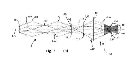
000 000 pixel to cover this FOV with regularly distributed pixels to satisfy
15 the highest resolution of the eye.
[0004] However, the resolution of an eye is not
evenly distributed. It
has high resolution only in some 20 FOV around its fovea. A full HD
display (1920x1080) covering 20 FOV already reaches retinal resolution at
fovea. The eye resolution gradually drops farther from fovea. Whole FOV
20 (outside fovea) can be covered with about the same amount of information
as inside the fovea putting the total number of pixels needed to some 4
000 000.
[0005] So called foveated rendering and
projection is being introduced
to virtual and mixed reality headsets to exploit exactly this feature of
25 human vision. But this is still performed with flat images. Light-field
devices do not have any solution yet for foveated projection.
CA 03155574 2022-4-21
WO 2021/090107 PCT/1B2020/060019
2
[0006] Document U520190324272 discloses a three-
dimensional (3D)
image display apparatus. The apparatus includes a plurality of light
sources; a spatial light modulator configured to modulate light from the
plurality of light sources according to 3D image information; and a focusing
5 optical system configured to focus an image formed by the spatial light
modulator onto a focal plane. The plurality of light sources may be
arranged such that multiple focal points, respectively corresponding to the
plurality of light sources, are formed on the focal plane near a pupil of a
user.
Summary
[0007] The present disclosure concerns a light-
field projection system,
comprising: a pin-light array comprising a plurality of point-lights and
generating an incident light-field illuminating an optical light modulator
configured for modulating the incident light-field and projecting a plurality
of modulated light-field components along a projection axis; a first optical
element configured for forming first pin-light images in a first pin-light
plane and modulator images in a modulator image plane; and a second
optical element defining an eye-box region and configured for forming
second pin-light images in a second pin-light plane within the eye-box;
20 wherein the first and second pin-light planes and modulator image plane
are substantially perpendicular to the projection axis and wherein the
modulator image plane is between the first optical element and second
optical element; and wherein the system further comprising at least one
optical device at the first pin-light plane and being configured to deflect at
25 least one of the modulated light-field components, such as to s
spatially
shift the modulator image in the modulator image plane.
[0008] The light-field projection system is able
to provide virtual and
mixed reality experience to the eyes of any human, animal or a camera. A
user of the light-field projection system can experience realistic mixing of
30 real and virtual 3D scenes. The light-field projection system is
suitable for
delivering 3D virtual and augmented reality information with the comfort
of the correct eye accommodation.
CA 03155574 2022-4-21
WO 2021/090107
PCT/1112020/060019
3
[0009] The light-field projection system can
comprise an eye-tracking
and steering device. The eye-tracking and steering device may be used to
determine where a viewer is looking to thereby determine where the
foveal region is in relation to the projected image.
5 [0010] The light-field projection system allows for foveated
projection.
In particular, the light-field projection system can create light-field which
provides higher angular resolution image in a narrow field of view (FOV)
and low angular resolution image for wide FOV. The light-field projection
system reduces the rendering workload by greatly reducing the image
10 quality in the peripheral vision (outside of the zone gazed by the
fovea).
Brief Description of the Drawings
[0011] The invention will be better understood
with the aid of the
description of an embodiment given by way of example and illustrated by
the figures, in which:
15 Fig. la illustrates a light-field projection system
comprising an
optical light modulator projecting modulated light-field components;
Figs. lb and lc show projected images of the optical light
modulator as seen by a viewer when a viewer's eye focuses at infinity (Fig.
1 b) and closer than at infinity (Fig. 1c);
20 Fig. 2a shows the light-field projection system comprising
an a
deflecting prism interacting with at least one of the modulated light-field
components, according to an embodiment;
Figs. 2b and 2c show projected images of the optical light
modulator of the system of Fig. 2a, when a viewer's eye focuses at infinity
25 (Fig. 2b) and closer than at infinity (Fig. 2c);
Fig. 2d shows a layout of a modulated light-field component
passing through the deflecting prism;
Fig. 3a shows the light-field projection system comprising a
plurality of deflecting prisms, according to an embodiment
CA 03155574 2022-4-21
WO 2021/090107 PCT/1112020/060019
4
Figs. 3b and 3c show projected images of the optical light
modulator of the system of Fig. 3a, when a viewer's eye focuses at infinity
(Fig. 3b) and closer than at infinity (Fig. 3c);
Figs. 4a and 4b show the optical device comprising an array of a
5 plurality of deflecting prisms (Fig. 4a) and a plurality of deflecting
prisms
and neutral optical elements (Fig. 4b), according to an embodiment;
Figs. 5a-c show a specific configuration of light-field projection
system of Fig. 3a (Fig. 5a) creating a patchwork of spatially separated
images seen by the viewer focusing at infinity (Fig. 5b) and closer than at
10 infinity (Fig. 5c), according to an embodiment;
Fig. 6a shows the light-field projection system comprising
offsetting lens interacting with at least one of the modulated light-field
components, according to an embodiment;
Figs. 6b and 6c show projected images of the optical light
15 modulator of the system of Fig. 6a, when a viewer's eye focuses at
infinity
(Fig. 6b) and closer than at infinity (Fig. 6c);
Fig. 7 illustrates the optical device comprising an array of a
plurality of offsetting lens, according to an embodiment;
Fig. 8a shows the light-field projection system comprising
20 imaging lens interacting with at least one of the modulated light-field
components, according to an embodiment;
Figs. 8b and 8c show projected images of the optical light
modulator of the system of Fig. 8a, when a viewer's eye focuses at infinity
(Fig. 8b) and closer than at infinity (Fig. 8c);
25 Fig. 9 illustrates the optical device comprising an array of
a
plurality of imaging lens, according to an embodiment;
Fig. 10 shows a pin-light array comprising an array of point lights;
Fig 11 illustrates a patchwork of projected second pin-light
images seen by a viewer using the light-field projection system comprising
30 deflecting prisms and the pin-light array comprising nine point-lights;
Fig. 12 illustrates a patchwork of projected second pin-light
images when the pin-light array comprising 25 point-lights;
CA 03155574 2022-4-21
WO 2021/090107 PCT/1112020/060019
Fig. 13 shows another example of patchwork of projected second
pin-light images;
Fig. 14 shows yet another example of patchwork of projected
second pin-light images;
5 Fig. 15 shows the light-field projection system, according
to an
alternative configuration;
Fig. 16 shows the light-field projection system, according to
another alternative configuration;
Fig. 17 shows the light-field projection system, according to yet
another alternative configuration.
Detailed Description of possible embodiments
[0012] Fig. la illustrates a light-field
projection system 1 comprising a
pin-light array 10 generating an incident light-field 100 illuminating an
optical light modulator 20 configured for modulating the incident light-
field 100 and projecting a plurality of modulated light-field components
110 along a projection axis 170. The system 1 further comprises a first pin-
light optical element 70 configured for forming first pin-light images 31 in
a first pin-light plane 30 substantially perpendicular to the projection axis
170.. The first pin-light optical element 70 can comprise an imaging lens.
20 The system 1 further comprises a second optical element 40 defining an
eye-box region 121 and configured for forming second pin-light images 120
in a second pin-light plane 124 within the eye-box 121. The second pin-
light plane 124 is substantially perpendicular to the projection axis 170.
The second pin-light plane 124 can correspond to a virtual image aperture,
25 or an exit pupil, within the eye box 121, the exit pupil 124 comprising
the
plurality of second pin-light images 120 (three second pin-light images 120
are represented in Fig. 2a).
[0013] Optionally, the light-field projection
system 1 can comprise a
modulator optical element 32 configured for forming modulator images
30 114 of the optical light modulator 20 in a modulator image plane 115,
also
substantially perpendicular to the projection axis 170. The modulator
CA 03155574 2022-4-21
WO 2021/090107 PCT/1112020/060019
6
image plane 115 is projected by the second optical element 40 at a distance
D from the eye-box region 121. The distance D can be infinity or any
distance along the projection axis 170, at either side of the eye-box region
121. The distance D at infinity or any distance along the projection axis 170
5 is typically outside the accommodation range of a viewer.
[0014] Alternatively, the modulator image plane
115 can be created by
the first pin-light optical element 70 with corresponding optical power or
by placing the first pin-light optical element 70 at a different distance
along the projection axis 170.
10 [0015] The second optical element 40 can comprise an eye piece. The
eye-piece 40 can comprise optical elements, such as a convex lens, mirror,
curved mirror, semi-transparent mirror or set of lenses, mirrors or semi-
transparent mirrors can be configured to place the modulator images 115
at an image distance D from the eye-box region 121. The distance D can be
15 set to infinity or any distance along the projection axis 170, at either
side of
the eye-box region 121.
[0016] The light-field projection system 1 can
comprise a Fourier filter 34
located at the first pin light plane 30. We note that the Fourier filter 34 is
not necessarily placed exactly in the Fourier plane of the optical light
20 modulator 20. For each viewpoint, the Fourier filter 34 can be
configured
to remove all but one diffraction component from the modulated light-
field components 110, that are reflected and diffracted on the optical light
modulator 20. Here, the term "viewpoint" corresponds to one modulated
light-field component 110.
25 [0017] The Fourier filter 34 can comprise at least one imaging lens
which
creates image plane of the modulated light-field component 110. The
Fourier filter 34 can comprise a pinhole array, for example made of an
optically non-transparent and non-translucent plate or other filtering
pattern. The Fourier filter 34 can be alternatively arranged in a reflection
30 mode, where the pinholes or other filtering pattern are substituted with
micromirrors. The Fourier filter 34 generates a modulated and filtered
CA 03155574 2022-4-21
WO 2021/090107 PCT/1112020/060019
7
virtual light-field 112. Here, the viewpoint corresponds to one light-field
component 110 passing through one pinhole.
[0018] The light-field projection system 1 is
destined to be worn by a
viewer for virtual and mixed reality applications. The light-field projection
5 system can be configured such that, when it is worn by the viewer the eye-
box 121, and the exit pupil 124, is within the viewer's eye 90. The second
optical element 40 transmits the modulated light-field components 110
towards the pupil 130 of the viewer's eye 90, such that the modulated
light-field components 110 are projected on the retina 92.
10 [0019] The double lines from each represented modulated light-field
component 110 are used to describe the limitation of real system which
need to be taken into account. Neither the pin-light array 10 nor the
Fourier filter 34 have zero aperture. The image of the optical light
modulator 20 must be treated in such a way that the light from each pixel
15 is projected towards the eye-box 121 (and thus towards the viewer's eye
90)
in more or less collimated narrow beam (the best is if it is slightly
converging to a point far behind the eye-box 121 so that viewer's eye 90
cannot focus on it and therefore all images in accommodation range of the
viewer appear similar).
20 [0020] Fig. lb shows projected images 140 of the optical light
modulator
20, for the three second pin-light images 120 when a viewer wear the light-
field projection system 1, when the viewer's eye 90 focuses at infinity.
[0021] Fig. lc shows the projected images 140
when the viewer's eye 90
focuses closer than at infinity. Here, the viewer sees three projected images
25 141, 142, 143 for each of the three second pin-light images 120, where
the
three projected images 141, 142, 143 are slightly shifted one with respect to
the other.
[0022] Fig. 2a shows the light-field projection
system 1, according to an
embodiment. The light-field projection system 1 further comprises at least
30 one optical device 60 at the first pin-light plane 30. The optical
device 60 is
CA 03155574 2022-4-21
WO 2021/090107 PCT/1112020/060019
8
configured for interacting with at least one of the modulated light-field
components 110. More particularly, the optical device comprises a
deflecting prism 60 configured to deflect one of the modulated light-field
components 110 such that the modulator image 114 is spatially shifted in
5 its modulator image plane 115. The spatial shift of the modulator image
114 in the modulator image plane 115 is indicated by the white triangles.
The non-shifted modulator images 114 are indicated by the black triangles.
The deflecting prism 60 does not change the location of the modulator
image 114 along the projection axis 170, relative to the modulator image
10 plane 115 without use of the prism 60. The rest of the optics (first and
second optical elements 70, 40 and modulator optical element 32) does also
not change the position of the modulator image 114 of the modulated
light-field component 110 that is deflected by the deflecting prism 60.
[0023] A layout of a modulated light-field
component 110 passing
15 through the deflecting prism 60 is shown in Fig. 2d. The deflection angle
OD can be defined as the angle from the incident modulated light-field
component 110a to the exit modulated light-field component 110b of the
exit of the deflection prism 60. The deflection angle OD depends on the
difference in orientation between the incident face 611 and the exit face of
20 the deflecting prism 60, or the apex angle O. in Fig. 2d. Other
configurations of the deflection prism 60 can be considered. For example,
the deflection prism 60 shape can includes uniform triangular prism having
equal base angles or can be substituted by a diffraction grating.
[0024] Fig. 2b shows projected images of the
optical light modulator 20,
25 i.e., the second pin-light images 120 when a viewer wear the light-field
projection system 1, when the viewer's eye 90 focuses at infinity. If one
calls "viewpoints" the second pin-light images 120 (and the first pin-light
images 31 in the first pin-light plane 30), then from the viewpoints, the
viewer sees a patchwork of projected images 140 corresponding to the FOV
30 of the viewer (in a plane). More particularly, the viewer sees a non-
shifted
projected image 141 corresponding to one of the non-deflected modulated
light-field components 110, and a shifted projected image 143
corresponding to the modulator images 114 spatially shifted in the
CA 03155574 2022-4-21
WO 2021/090107 PCT/1112020/060019
9
modulator image plane 115 by the deflecting prism 60 and projected by the
eye-piece 40 to a distance D from the exit pupil 124.
[0025] Fig. 2c shows the projected images 140
when the viewer's eye 90
focuses closer than at infinity. The shifted projected image 143,
5 corresponding to the modulator images 114 spatially shifted in the
modulator image plane 115 by the deflecting prism 60, has larger shift
relative to the projected images 141, 142 corresponding to the modulator
images 114 of the non-deflected modulated light-field components 110.
[0026] In Fig. 3a, the light-field projection
system 1 is represented
10 comprising two deflecting prisms 60, wherein each deflecting prism 60 is
configured to deflect one of the modulated light-field components 110 by
a predetermined angle. Figs. 3b and 3c compare the non-shifted projected
image 142 with the shifted projected images 141, 143 seen by the viewer
focusing at infinity (Fig. 3b) and seen by the viewer focusing at a distance
15 closer than infinity (Fig. 3c).
[0027] The spatial shift of the two deflected
modulated light-field
components 110 is shown by the white triangles while the position in the
modulator image plane 115 of the non-deflected modulated light-field
components 110 is indicated by the black triangles.
20 [0028] The light-field projection system 1 can comprise more than
two
deflecting prisms 60 in order to deflect a plurality of modulated light-field
components 110.
[0029] Figs. 4a and 4b show a cross-section view
of the optical device
comprising an array 160 including a plurality of deflecting prisms 60. For
25 example, the array 160 can be an array of microprisms.
[0030] The array 160 can be configured such that
each deflecting prisms
60 interacts with one modulated light-field component 110. The array 160
can further be configured such that each deflecting prisms 60 interacts with
more than one modulated light-field component 110, or such that multiple
CA 03155574 2022-4-21
WO 2021/090107
PCT/1112020/060019
prisms 60 perform identical optical transformation on multiple light-field
components 110.
[0031] In one aspect, the array 160 is configured
such that different
deflecting prisms 60 of the array 160 may have different apex angle Oa. In
5 the example of Figs. 4a and 4b, the apex angle Oa increases from the
center
of the array 160 to the periphery, such that the modulated light-field
components 110 are deflected with increasing deflection angle OD from the
center toward the periphery of the array 160. Other configurations of the
deflecting prisms 60 in the array 160 is possible. For example, the apex
10 angle Oa of the deflecting prisms 60 can decrease from the center of the
array 160 to the periphery or can be substantially the same for all
deflecting prisms 60 in the array 160.
[0032] In one aspect, the array 160 comprises at
least one neutral optical
element 61. The modulated light-field component 110 interacting with
15 such neutral optical element 61 is not spatially shift the modulator
image
plane 115. The modulator image 114 of the modulated light-field
component 110 interacting with such neutral optical element 61 is also not
shifted along the projection axis 170, relative to the modulator image
plane 115.
20 [0033] The neutral optical element 61 can comprise a flat lens. In
Fig.
4a, the array 160 comprises a neutral optical element 61 in the center of
the array 160. In the example of Fig. 4b, the array 160 comprises deflecting
prims 60 and neutral optical elements 61 in alternance, from the center to
the periphery of the array 160. The center of the array is made of a neutral
25 optical elements 61. The Fourier filter 34 is also represented in Figs.
4a and
4b.
[0034] Fig. 5a shows a specific configuration of
the light-field projection
system 1 of Fig. 3, where two modulated light-field components 110 are
deflected by the prism array 160 to such an extent that they do not overlap
30 in the FOV of the viewer, but create a patchwork of spatially separated
images 141 and 143. Fig. 5b shows the non-shifted image 142 and shifted
CA 03155574 2022-4-21
WO 2021/090107
PCT/1112020/060019
11
images 141, 143 seen by the viewer focusing at infinity and Fig. 5c shows
the non-shifted image 142 and shifted images 141, 143 seen by the viewer
focusing at a distance closer than infinity. Their partial overlap with other
viewpoints constitutes a light-field, while the periphery is covered by single
5 images passing through their individual viewpoints.
[0035] Fig. 6a shows the light-field projection
system 1 comprising
offsetting lenses 64 interacting with the modulated light-field components
110. Each of the offsetting lens 64 is configured such that the modulated
light-field component 110 is spatially shifted in the modulator image plane
10 115 and such that the modulator image 114 of the modulated light-field
component 110 is shifted along the projection axis 170 relative to the
modulator image plane 115. In Fig. 6a, the black triangles show that the
deflected modulated light-field components 110 are not spatially shifted in
the modulator image plane 115 but that the corresponding modulator
15 images 114 are shifted along the projection axis 170 to the left of the
modulator images 115 of the non-deflected modulated light-field
component 110 being in the modulator image plane 115.
[0036] The offsetting lens 64 can be made from an
imaging lens lenses
combined with a deflection prism.
20 [0037] In Fig. 6a, the two offsetting lenses 64 at the periphery of
the
first pin-light plane 30 can be formed from cut out parts of a same imaging
lens, and different from the offsetting lens 64 at the center of the first pin-
light plane 30. The modulated light-field components 110 passing through
the two peripheric offsetting lens 64 may thus generate modulator images
25 114 that is shifted along the projection axis 170 relative to the
modulator
image plane 115 and relative to the position of the modulator image 114
generated by the modulated light-field component 110 passing through
the central offsetting lens 64.
[0038] Fig. 6b shows the non-shifted image 141
and shifted images 143
30 seen by the viewer focusing at infinity. Fig. fic shows the non-shifted
image
142 and shifted images 141, 143 seen by the viewer focusing at a distance
CA 03155574 2022-4-21
WO 2021/090107
PCT/1112020/060019
12
closer than infinity. In this configuration, the system 1 displays the
modulated light-field component 110 by using two different base depth
planes by which it generates full range of depths in the same way like the
system with one base depth plane. Here, the expression "base depth
5 plane" corresponds to an image plane of the optical light modulator 20 as
seen by the viewer. In Figs. 6a-6c, the offsetting lenses 64 cause a viewer to
see the images in different image plane (or base depth planes) of the
optical light modulator 20 SLM, depending on the offsetting lens 64 being
traversed by the modulated light-field components 110. Having at least
one another base depth plane can be useful for displaying high spatial-
frequency images or classical flat content, such as text, at different image
distance D from the eye-box region 121 than the rest of the image. Such a
different image distance D can be about 50 cm. Another base depth plane
can further be used for non-light-field part of the scene at infinity, etc.
15 [0039] The system 1 can provide better resolution images in the
specific
depths or it can be used as a projector of volumetric images with only
several distinct depths such as one flat screen closer and second farther, or
combination of a flat screen and a light-field.
[0040] Fig. 7 shows a cross-section view of the
optical device comprising
20 an array 160 including a plurality of offsetting lens 64. In a possible
variant, the array 160 comprising offsetting lens 64 can be obtained from a
rings cut out from different imaging lenses and assembled together and
concentric. Alternatively, the array 160 comprising offsetting lens 64 can
be obtained from cubes cut from an imaging lense such as to create an
25 array of different concentric imaging lens portions where several, not
necessarily symmetrically distributed portions being part of the same
original imaging lens, with the axis of the concentric lenses coinciding with
the axis of the whole optical system.
[0041] In one aspect, the array 160 comprising
offsetting lens 64 further
30 comprises one or several neutral optical elements 61, similarly to the
microprism array described with Figs. 4a and 4b.
CA 03155574 2022-4-21
WO 2021/090107
PCT/1112020/060019
13
[0042] For example, if the modulated light-field
components 110 are
projected simultaneously through the array 160 comprising offsetting lens
64, the corresponding modulator images 114 will be formed at different
optical distances along the projection axis 170. The modulated light-field
5 components 110 are also deflected by the offsetting lens 64, spatially
shifting the modulator images 114 in the modulator image plane 115.
Thus, the light-field projection system 1 comprising the array 160 of
offsetting lens 64 creates images at different optical distances along the
projection axis 170 and at different positions in the modulator image plane
10 115.
[0043] In one aspect, the array 160 comprising
offsetting lens 64 may
further comprise one or several deflecting prisms 60.
[0044] In another embodiment illustrated in Fig.
8a, the light-field
projection system 1 comprises at least one imaging lens 63 configured to
15 shift the modulator image 114 of the modulated light-field component 110
passing through the imaging lens 63 along the projection axis 170, relative
to the modulator image plane 115. The imaging lens 63 does not
substantially spatially shift the modulated light-field components 110 in the
modulator image plane 115. This can be seen from the shifted position
20 (white triangles) of the modulator images 114 along the projection axis
170
of the modulated light-field components 110 passing through the imaging
lens 63, relative to the non-shifted modulator images 114 (black triangles)
of the modulated light-field components 110 that do not pass through the
imaging lens 63.
25 [0045] In contrast to the deflecting prism 60, the imaging lens 63
(and
the offsetting lens 64) changes the vergence of the modulated light-field
components 110 beam. The deflecting prism 60 does not change the
vergence of the modulated light-field components 110 beam (it remains
collimated), while it produces convergent (or divergent) modulated light-
30 field component 110 beams. Thus the imaging lens 63 changes the optical
position of the modulator images 114 along the projection axis 170.
CA 03155574 2022-4-21
WO 2021/090107
PCT/1112020/060019
14
[0046] This plays a role when the pin-lights and
holes in the Fourier
filter have considerably large diameter (such as more than 1 mm). It is
therefore possible to display images in different optical distances
depending on through which lens the image component passed
5 [0047] Fig. 8b shows the image 143, 142, 141 seen by the viewer
focusing at infinity. Flgs. 8c shows the image 143, 142, 141 seen by the
viewer focusing at a distance closer than infinity. In addition to their
apparent spatial shift, the images 143, 142, 141 can also blur or sharpen
depending on the optical distance of each of the subimage. Here, the term
10 "subimage" corresponds to a modulated light-field component 110 of one
viewpoint. The subimage can be considered to be in focus since the depth
of field is small due to the small modulated light-field component 110 and
the pinhole. In reality, however, each viewpoint has also its own optical
distance which plays a role especially when the modulated light-field
15 component 110 and the pinhole are not small enough. Thus, the optical
distance of each of the subimage may vary.
[0048] Fig. 9 shows a cross-section view of the
optical device comprising
an array 160 including a plurality of imaging lens 63. In a possible variant,
the array 160 comprising imaging lens 64 can further comprise one or
20 several neutral optical elements 61.
[0049] In an aspect, the light-field projection
system 1 can comprise any
one or a plurality, alone or in combination of the deflecting prism 60, the
neutral optical element 61, the imaging lens 63 and the offsetting lens 64.
Of course, in order to obtain spatial shift in the modulator image plane 115
25 of the modulated light-field components 110, the light-field projection
system 1 must comprise at least a deflecting prism 60 or an offsetting lens
64.
[0050] In an embodiment, the array 160 is
configured to interact with
each of said modulated light-field components 110.
CA 03155574 2022-4-21
WO 2021/090107
PCT/1112020/060019
[0051] In an aspect, one modulated light-field
components 110 passes
through an optical device 60, 61, 63, 64 of the array 160.
[0052] Fig. 10 shows a possible implementation of
the pin-light array 10
comprising an array containing 100 pin lights 101. The pin lights 101 can
5 be illuminated simultaneously such that the modulated light-field
components 110 are projected simultaneously. Alternatively, the pin lights
101 can be illuminated sequentially such that the modulated light-field
components 110 are projected sequentially. The latter option is shown in
Fig. 10 by the active pin lights 101a and the inactive pin lights 101b. The
10 active pin lights 101a project incident light-fields 100 illuminating
the
optical light modulator 20, such as to project the corresponding modulated
light-field components 110 along a projection axis 170. In Fig. 10; the
numerals 1 to 8 illustrate a possible sequence of illumination of the
different pin lights 101 in the pin-light array 10. Other illumination
15 sequences can also be considered.
[0053] Fig 11 illustrates a patchwork of
projected modulator images 114
as would be seen by a viewer using the light-field projection system 1
comprising the microprism array 160 at the first pin-light plane 30 and a
pin-light array 10 comprising nine pin-lights 101. The external periphery of
20 the rectangle corresponds to the size of the projected image 144
corresponding to the FOV of the viewer (in a plane). All nine modulator
images 114 (viewpoints) overlap in a central area 145 of the projected
image. There is less and less overlap of the modulator images 114 farther
from the central area 145. There is only one modulator image 114 in the
25 corners. Thus, the central area 145 corresponds to a narrow FOV having
high light-field and color resolution and the peripheral area corresponds to
a wider FOV having lower light-field (depth) and color resolution. In other
words the central area 145 corresponds to a foveated area having high
light-field and color resolution. The light-field projection system 1 can thus
30 provide a combination of high light-field and color resolution in narrow
FOV and low resolution in large FOV.
CA 03155574 2022-4-21
WO 2021/090107
PCT/1112020/060019
16
[0054] Fig. 12 illustrates a patchwork of
projected modulator images 114
as would be seen by a viewer using the light-field projection system 1
comprising the microprism array 160 at the first pin-light plane 30 and a
pin-light array 10 comprising 25 point-lights 101. The same reasoning holds
5 as for Fig. 11 while showing the situation of more realistic higher
resolution
system.
[0055] Fig. 13 shows another example of patchwork
of projected
modulator images 114 distributed by deflecting prisms 60 so that the center
area 145 creates multi-component light-field (comprising a plurality of
10 modulator images 114) while the periphery is covered by 8 individual
shifted modulator images 114.
[0056] Flg. 14 shows another example of patchwork
of projected
modulator images 114, where the modulated light-field components 110
are projected simultaneously through the array 160 such as to create the
15 wide FOV peripheral image with low angular, color and depth resolution
while the center area 145 creates high resolution multi-component light-
field (comprising a plurality of modulator images 114).
[0057] In an embodiment, the light-field
projection system 1 comprises
an eye-tracking and projection steering device. The eye-tracking and
20 projection steering device may be used to determine where a viewer is
looking to thereby determine where the foveal region is in relation to the
projected image 144. Here, the foveal region corresponds to the center
area 145 of the projected image 144.
[0058] It is understood that the present
invention is not limited to the
25 exemplary embodiments described above and other examples of
implementations are also possible within the scope of the patent claims.
[0059] The optical light modulator 20 can
comprise a spatial light
modulator (SLM), for example a transmissive spatial light modulator or a
reflective spatial light modulator. The SLM can comprises a fast reflective
30 SLM such as a liquid crystal on silicon (LCoS) or a ferroelectric liquid
crystal
CA 03155574 2022-4-21
WO 2021/090107
PCT/1112020/060019
17
on silicon (FLCoS), a digital micromirror device (DMD), or other suitable
modulator.
100601 The light-field projection system 1 can
comprise a collimating or
partly collimating lens 50. The pin-light array 10 illuminates the optical
5 light modulator 20 through the collimating or partly collimating lens 50.
The collimating or partly collimating lens 50 can comprise reflective or
holographic element having the same function as a collimating or partly
collimating lens.
100611 Fig. 15 shows the light-field projection
system 1 according to an
10 alternative configuration whereby the collimating or partly collimating
lens
50 and the first pin-light optical element 70 can be the same optical
element being placed on the surface of a reflective spatial light modulator
20.
100621 Fig. 16 shows the light-field projection
system 1 according to an
15 alternative configuration whereby the collimating or partly collimating
lens
50 and the first pin-light optical element 70 are the same optical element
being placed on the surface of a reflective spatial light modulator 20.
Moreover, the pin-light array 10 coincides with the optical device 60, 61, 63,
64 in the first pin-light plane 30. The pin-light array 10 may also coincide
20 with the Fourier filter 34 if such filter is present. In such
configuration, the
pin-light array 10 should comprise holes (openings) to let the modulated
light-field components 110 pass through the pin-light array 10 and reach
the modulator optical element 32.
100631 Fig. 17 shows the light-field projection
system 1 according to
25 another alternative configuration whereby the second optical element 40
comprises a combiner. The combiner 40 is configured for reflecting the
modulated light-field components 110 coming from the modulator optical
element 32 and for forming second pin-light images 120 in the second pin-
light plane 124 within the eye-box 121. The combiner 40 can comprise
30 waveguides with holographic grating which provide images in a fixed
focal
plane (a stack of waveguides can be used to provide multiple focal planes),
CA 03155574 2022-4-21
WO 2021/090107
PCT/1112020/060019
18
a holographic reflector including a holographic pattern, a dome shape
semi-transparent mirrors with a beam splitter or an ellipsoid combiner. The
combiner 40 can further comprise a semi-transparent first element
including a first reflecting surface having a concave and ellipsoid shape.
5 The combiner 40 can further comprise a general free-form surface. The
combiner 40 can comprise array of differently or identically inclined
mirrors.
100641 The combiner can be further configured for
transmitting natural
light from the real world towards the eye box, such that both projected
10 virtual light-field and natural light are projected, via the combiner,
within
the eye box region 121.
CA 03155574 2022-4-21
WO 2021/090107
PCT/1112020/060019
19
Reference Numbers and Symbols
pin-light array
optical light modulator, spatial light modulator (SLM),
first pin-light plane
5 31 first pin-light images
32 modulator optical element
34 Fourier filter
second optical element
collimating or partly collimating lens
10 60 deflecting prism
61 neutral optical element
63 imaging lens
64 offsetting lens
70 first pin-light optical element
15 90 eye
92 retina
100 incident light-field
101 point-light
101a active point-light
20 101b inactive point-light
110 modulated light-field component
110a incident modulated light-field
component
110b exit modulated light-field component
112 modulated and filtered virtual light-
field
25 114 modulator image
115 modulator image plane
120 second pin-light images, viewpoints
121 eye-box region
124 second pin-light plane, exit pupil
30 130 pupil
140, 141 projected image
142, 143 projected image
145 central area of the projected image
160 microprism array
35 162 imaging lens array
163 lens element
164 offsetting lens array
165 offsetting lens element
170 projection axis
40 Oa apex angle
OD deflection angle
D image distance
CA 03155574 2022-4-21