Note: Descriptions are shown in the official language in which they were submitted.
WO 2021/118984
PCT/US2020/063757
TITLE
VEHICLE WHEELS ANT) METHODS OF MAKING VEHICLE WHEELS
FIELD OF USE
100011 The present disclosure relates to vehicle wheels and methods of making
vehicle
wheels.
BACKGROUND
100021 Vehicle wheels comprising undesired mass distributions can causes
vibrations and/or
poor fuel mileage during operation of a vehicle. To correct the undesired mass
distributions,
wheel weights can be added to regions of the vehicle wheels in order to
balance the vehicle
wheels. Additionally, the mass of the vehicle wheels can affect the fuel
mileage of the
vehicle. Designing vehicle wheels to accept wheel weights and achieve
desirable fuel
mileage of a vehicle presents challenges.
SUMMARY
100031 According to one aspect of the present disclosure, a vehicle wheel is
provided. The
vehicle wheel comprises a generally annular first region, a second region, and
a flange
region. The first region comprises an outer surface, an inner surface, a first
end, and a second
end. The second region extends radially inwardly from the first region, and
the second region
is configured to mount to a vehicle axle. The flange region extends from the
first region.
The flange region comprises a first flange end adjacent to the first end of
the first region, a
second flange end, and a curved elongate portion extending intermediate the
first flange end
and the second flange end. The curved elongate portion comprises a first
thickness no greater
than 0.3 inches and a second thickness greater than 0.3. The vehicle wheel
comprises
aluminum or an aluminum alloy.
100041 According to another aspect of the present disclosure, a vehicle wheel
is provided.
The vehicle wheel comprises a generally annular first region, a second region,
a first flange
region, and a second flange region. The first region comprises an outer
surface, an inner
surface, a first end, and a second end. The second region extends radially
inwardly from the
first region adjacent to the first end of the first region. The second region
is configured to
1
CA 03155781 2022-4-22
WO 2021/118984
PCT/US2020/063757
mount to a vehicle axle. The first flange region extends from the first
region. The first flange
region comprises a first flange end adjacent to the first end of the first
region, a second flange
end, and a first curved elongate portion extending intermediate the first
flange end and the
second flange end. The first curved elongate portion comprises a first
thickness no greater
than 03 inches and a second thickness greater than 03 inches. The second
flange region
extends from the first region, opposite the first flange region. The second
flange region
comprises a third flange end adjacent to the second end of the first region, a
fourth flange
end, and a second curved elongate portion extending intermediate the third
flange end and the
fourth flange end. The second curved elongate portion comprises a third
thickness no greater
than 03 inches and a fourth thickness greater than 0.3 inches. The vehicle
wheel comprises
aluminum or an aluminum alloy.
100051 According to yet another aspect of the present disclosure, a method of
making a
vehicle wheel is provided. The method comprises providing a vehicle wheel by a
method
comprising at least one of forming, curing, forging, casting, and additive
manufacturing. The
vehicle wheel comprises at least one of metal and a metal alloy. The vehicle
wheel
comprises a generally annular first region, a second region, and a flange
region. The first
region comprises an outer surface, an inner surface, a first end, and a second
end. The second
region extends radially inwardly from the first region, and the second region
is configured to
mount to a vehicle axle. The flange region extends from the first region. The
flange region
comprises a first flange end adjacent to the first end of the first region, a
second flange end,
and a curved elongate portion extending intermediate the first flange end and
the second
flange end. The curved elongate portion comprises a first thickness no greater
than 0.3
inches and a second thickness greater than 0.3 inches. The vehicle wheel
comprises
aluminum or an aluminum alloy.
100061 It is understood that the inventions disclosed and described in this
specification are
not limited to the aspects summarized in this Summary. The reader will
appreciate the
foregoing details, as well as others, upon considering the following detailed
description of
various non-limiting and non-exhaustive aspects according to this
specification.
2
CA 03155781 2022-4-22
WO 2021/118984
PCT/US2020/063757
BRIEF DESCRIPTION OF THE DRAWINGS
[0007] The features and advantages of the examples, and the manner of
attaining them, will
become more apparent, and the examples will be better understood, by reference
to the
following description taken in conjunction with the accompanying drawings,
wherein:
[0008] FIG. 1 is a front perspective view of a non-limiting embodiment of a
vehicle wheel
according to the present disclosure;
[0009] FIG. 2 is a cross-sectional detail view of a portion of the vehicle
wheel of FIG. 1
taken along line 2-2 of FIG. 1;
100101 FIG. 3 is a detail view of area 3 of FIG. 2;
[0011] FIG. 4 is a detail view of area 4 of FIG. 2;
[0012] FIG. 5A is a perspective view of a non-limiting embodiment of a wheel
weight;
[0013] FIG. 5B is a cross-sectional view of the wheel weight of FIG. 5A taken
along line 58-
5B of FIG. 5A; and
[0014] FIG. 6 is a cross-sectional detailed view of area 4 of the vehicle
wheel of FIG. 2 with
the wheel weight of FIG. 5A installed thereon.
[0015] Corresponding reference characters indicate corresponding parts
throughout the
several views. The exemplifications set out herein illustrate certain
embodiments, in one
form, and such exemplifications are not to be construed as limiting the scope
of the appended
claims in any manner.
DETAILED DESCRIPTION
[0016] Various embodiments are described and illustrated herein to provide an
overall
understanding of the structure, function, and use of the disclosed articles
and methods. The
various embodiments described and illustrated herein are non-limiting and non-
exhaustive.
Thus, an invention is not limited by the description of the various non-
limiting and non-
exhaustive embodiments disclosed herein. Rather, the invention is defined
solely by the
claims. The features and characteristics illustrated and/or described in
connection with
various embodiments may be combined with the features and characteristics of
other
3
CA 03155781 2022-4-22
WO 2021/118984
PCT/US2020/063757
embodiments. Such modifications and variations are intended to be included
within the
scope of this specification. As such, the claims may be amended to recite any
features or
characteristics expressly or inherently described in, or otherwise expressly
or inherently
supported by, this specification. Further, Applicant reserves the right to
amend the claims to
affirmatively disclaim features or characteristics that may be present in the
prior art. The
various embodiments disclosed and described in this specification can
comprise, consist of,
or consist essentially of the features and characteristics as variously
described herein.
[0017] Any references herein to "various embodiments," "some embodiments,"
"one
embodiment," "an embodiment," or like phrases mean that a particular feature,
structure, or
characteristic described in connection with the example is included in at
least one
embodiment. Thus, appearances of the phrases "in various embodiments," "in
some
embodiments," "in one embodiment," "in an embodiment," or like phrases in the
specification do not necessarily refer to the same embodiment. Furthermore,
the particular
described features, structures, or characteristics may be combined in any
suitable manner in
one or more embodiments. Thus, the particular features, structures, or
characteristics
illustrated or described in connection with one embodiment may be combined, in
whole or in
part, with the features, structures, or characteristics of one or more other
embodiments
without limitation. Such modifications and variations are intended to be
included within the
scope of the present embodiments.
100181 In this specification, unless otherwise indicated, all numerical
parameters are to be
understood as being prefaced and modified in all instances by the term
"about," in which the
numerical parameters possess the inherent variability characteristic of the
underlying
measurement techniques used to determine the numerical value of the parameter.
At the very
least, and not as an attempt to limit the application of the doctrine of
equivalents to the scope
of the claims, each numerical parameter described herein should at least be
construed in light
of the number of reported significant digits and by applying ordinary rounding
techniques.
[0019] Also, any numerical range recited herein includes all sub-ranges
subsumed within the
recited range. For example, a range of "1 to 10" includes all sub-ranges
between (and
including) the recited minimum value of 1 and the recited maximum value of 10,
that is,
having a minimum value equal to or greater than I and a maximum value equal to
or less than
10. Also, all ranges recited herein are inclusive of the end points of the
recited ranges. For
example, a range of"! to 10" includes the end points 1 and 10. Any maximum
numerical
4
CA 03155781 2022-4-22
WO 2021/118984
PCT/US2020/063757
limitation recited in this specification is intended to include all lower
numerical limitations
subsumed therein, and any minimum numerical limitation recited in this
specification is
intended to include all higher numerical limitations subsumed therein.
Accordingly,
Applicant reserves the right to amend this specification, including the
claims, to expressly
recite any sub-range subsumed within the ranges expressly recited. All such
ranges are
inherently described in this specification.
100201 The grammatical articles "a," "an," and "the," as used herein, are
intended to include
"at least one" or "one or more," unless otherwise indicated, even if "at least
one" or "one or
more" is expressly used in certain instances. Thus, the foregoing grammatical
articles are
used herein to refer to one or more than one (i.e., to "at least one") of the
particular identified
elements. Further, the use of a singular noun includes the plural and the use
of a plural noun
includes the singular, unless the context of the usage requires otherwise.
[0021] As used herein, a referenced element or region that is "intermediate"
two other
elements or regions means that the referenced element/region is disposed
between, but is not
necessarily in contact with, the two other elements/regions. Accordingly, for
example, a
referenced element that is "intermediate" a first element and a second element
may or may
not be immediately adjacent to or in contact with the first and/or second
elements, and other
elements may be disposed between the referenced element and the first and/or
second
elements.
[0022] Typically, different wheel weights are used to balance different
vehicle wheel types
(e.g., sizes, materials). For example, a wheel weight used to balance a steel
vehicle wheel
may be different than a wheel weight used to balance an aluminum vehicle
wheel. Stocking
multiple varieties of wheels weights can be costly, and determining which of
the variety of
wheel weights to use on a particular vehicle wheel can be time consuming.
Additionally, the
inventors of the present disclosure discovered the flange regions of vehicle
wheels can be
susceptible to gutter cracks and wear that can result in a failure of the
vehicle wheel or a tire
mounted to the vehicle wheel. Accordingly, vehicle wheels and methods of
making vehicle
wheels are provided herein that can include a mounting feature accepting a
wheel weight
common to various types and/or sizes of wheels (e.g., an 17 series wheel
weight 550 as
illustrated in FIGs. 5A-5B), reduce the occurrence of gutter cracks, and/or
reduce the
occurrence of wear to flange regions of the wheel. For example, the 17 series
wheel weight
CA 03155781 2022-4-22
WO 2021/118984
PCT/US2020/063757
550 can be installed on the vehicle wheel according to the present disclosure
as shown in
FIG. 6, described below.
100231 Additionally, a sturdy vehicle wheel can be heavy, which can reduce
vehicle mileage
and increase vehicle fuel costs. According to the present disclosure, a
vehicle wheel is
provided that can comprise a sturdy structure suitable to support a load
carried by the vehicle
and which has a decreased mass relative to certain conventional vehicle
wheels. The
decreased mass can result in fuel savings while operating the vehicle.
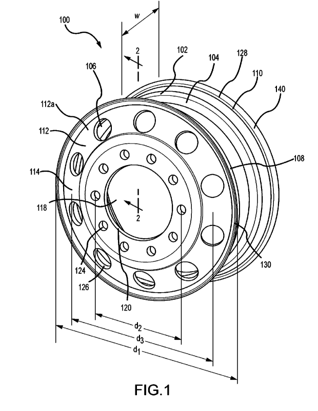
100241 FIGs. 1-4 illustrate a non-limiting embodiment of a vehicle wheel
according to the
present disclosure. The vehicle wheel 100 comprises a first region 102, a
second region 112,
a flange region 130, and a flange region 140. The first region 102 can be
generally annular
and can comprise an outer surface 104, an inner surface 106, a first end 108,
and a second
end 110. The outer surface 104 can comprise a tire mount 128, which can be
disposed about
a circumference of the outer surface 104 of the first region 102. The tire
mount 128 can be
configured so that a tire can be mounted thereon. For example, the tire mount
128 can, as
shown, comprise a tire bead set configured to receive a tire. The tire can
comprise any
suitable dimensions for mounting on the tire mount 128. For example, depending
on the
dimensions of the tire mount 128, the tire can comprise dimensions of 11R22.5,
295/75R22.5,
11R24.5, 285/75R24.5, or other suitable dimensions.
100251 The first region 102 can comprise a nominal rim width and a nominal rim
diameter
adapted to receive a tire. In various non-limiting embodiments, the first
region 102 can
comprise a nominal rim width, w, in a range of 1 inch (2.54 mm) to 100 inches
(2540 mm),
such as, for example, 6 inches (152.4 mm) to 24 inches (609.6 mm), or 6 inches
(152.4 mm)
to 12 inches (304.8 mm). For example, and without limitation, in certain non-
limiting
embodiments, the nominal rim width, w, of the first region 102 can be 8.25
inches (209.6
mm) or 11 inches (279.4 mm).
100261 In various non-limiting embodiments, the first region 102 can comprise
a nominal rim
diameter, di, in a range of 1 inch (2.54 mm) to 200 inches (5080 mm), such as,
for example,
14 inches (406.4 mm) to 25 inches (635 mm), or 19 inches (482.6 mm) to 25
inches (635
mm). For example, and without limitation, in certain non-limiting embodiments,
the nominal
rim diameter, di, of the first region 102 can be 22.5 inches (571.5 mm) or
24.5 inches (622.3
mm).
6
CA 03155781 2022-4-22
WO 2021/118984
PCT/US2020/063757
100271 In various embodiments, the first region 102 can comprise a valve stem
mount (not
shown). The valve stem mount can be configured to receive a valve stem in
order to control
gas transport into and out of a tire mounted on the tire mount 128.
[0028] The second region 112 can extend radially inwardly from the first
region 102. In
certain non-limiting embodiments, the second region 112 is integral with and
extends radially
inwardly from the inner surface 106 of the first region 102. In various non-
limiting
embodiments, the second region 112 extends in a direction that is
substantially perpendicular
to the inner surface 106 of the first region 102. The second region 112 can
comprise a first
surface 114, a second surface 116, and an opening 118 extending from the first
surface 114 to
the second surface 116.
[0029] The second region 112 can be configured to mount to a vehicle axle (not
shown). For
example, the opening 118 can be configured to receive at least a portion of a
hub of the
vehicle axle. Additionally, a hub surface 120 of the second region 112 can be
configured to
engage the hub of the vehicle axle and facilitate alignment of the vehicle
wheel 100 with the
hub of the vehicle axle. In various non-limiting embodiments, the hub surface
120 can
comprise a pilot bore suitable to engage a pilot tab of the hub of the vehicle
axle.
[0030] In various non-limiting embodiments, the second region 112 can comprise
at least two
bores 124 extending from the first surface 114 to the second surface 116. Each
of the at least
two bores 124 can be configured to receive a stud on a hub of a vehicle axle.
Center points of
each of bores 124 can be disposed evenly about a mounting circle. In various
non-limiting
embodiments, the mounting circle has a center common with the second region
112. In
various non-limiting embodiments, the mounting circle can comprise a diameter,
d2, in a
range of 1 inch (25.4 mm) to 15 inches (381 mm). For example, the diameter,
d2, can be
11.25 inches (285.75 mm). In various non-limiting embodiments, each bore 124
can have a
diameter in a range of 0.1 inches (2.54 mm) to 2 inches (50.8 mm). For
example, each bore
124 can have a diameter of 1.023 inches (26 mm). In various non-limiting
embodiments, the
second region 112 can comprise ten bores 124.
[0031] In various non-limiting embodiments, the second region 112 can comprise
at least two
peripheral openings 126 disposed about a periphery 112a of the second region
112 and
proximal to the first region 102. The at least two peripheral openings 126 can
reduce a
weight of the vehicle wheel 100. In various non-limiting embodiments, the
second region
7
CA 03155781 2022-4-22
WO 2021/118984
PCT/US2020/063757
112 can comprise ten peripheral openings 126. In various non-limiting
embodiments, the
peripheral openings 126 can be disposed about the second region 112 offset
from the bores
124, as illustrated in FIG. 1, or can be disposed about the second region 112
substantially in
line with the bores 124 (not shown). An offset disposition of the bores 124
and the peripheral
openings 126, such as is shown in FIG. 1, can increase a load rating of the
vehicle wheel 100.
In various non-limiting embodiments, each peripheral opening 126 can be
disposed evenly
about a peripheral circle. In various non-limiting embodiments, the peripheral
circle has a
center common with the second region 112. The peripheral circle, for example,
can comprise
a diameter, d3, in a range of 2 inches (50.8 mm) to 22 inches (558.8 mm). For
example, the
diameter, d3, can be 17.3 inches (439.42 mm).
100321 Referring to FIG. 3, the flange region 130 can extend from the first
region 102. The
flange region 130 can comprise a first flange end 132 adjacent to the first
end 108 of the first
region 102, a second flange end 134, and a curved elongate portion 136
extending
intermediate the first flange end 132 and the second flange end 134.
Similarly, referring to
FIG. 4, the flange region 140 can extend from the first region 102 opposite
the first flange
region 130. The flange region 140 can comprise a first flange end 142 adjacent
to the second
end 110 of the first region 102, a second flange end 144, and a curved
elongate portion 146
extending intermediate the first flange end 142 and the second flange end 144.
In various
non-limiting embodiments, the flange region 140 can be a mirror image of the
flange region
130. In certain non-limiting embodiments, the flange regions 130 and 140 are
configured to
receive and engage a wheel weight (e.g., a clip-on wheel weight), such as, for
example, an 17
series wheel weight as illustrated in FIGs. 5A-5B and as described below with
reference to
FIG. 6.
100331 Referring again to FIG. 3, in certain non-limiting embodiments of
vehicle wheel 100
the curved elongate portion 136 can comprise an inner curved surface 136a
comprising an
inner radius of curvature, rt, and a first outer curved surface 136b
comprising an outer radius
of curvature, n. Each radius of curvature, rt and r2, can have the same center
or different
centers. For example, as shown in FIG. 3, when the radii of curvature, rt and
r2, have
different centers (as represented by dots), the thickness of the curved
elongate portion 136
can vary along its. In certain non-limiting embodiments, as shown in FIG. 3,
the center of the
outer radius of curvature, n, can be closer to inner curved surface 136a than
the center of the
inner radius of curvature, rt. In various non-limiting embodiments, the
thickness of the
8
CA 03155781 2022-4-22
WO 2021/118984
PCT/US2020/063757
curved elongate portion 136 can decrease (e.g., taper) as one moves away from
the first
region 102. The first outer curved surface 136b can extend a first distance
and the inner
curved surface 136a can extend a second distance greater than the first
distance.
100341 Similarly, referring to FIG. 4, in certain non-limiting embodiments of
vehicle wheel
100 the curved elongate portion 146 can comprise an inner curved surface 146a
comprising
an inner radius of curvature, n, and a first outer curved surface 146b
comprising an outer
radius of curvature, r4. Each radius of curvature, n and r4, can have the same
center or
different centers. For example, as shown in FIG. 4, when the radii of
curvature, n and r4,
have different centers (as represented by dots), the thickness of the curved
elongate portion
146 can vary along its length. In certain embodiments, as shown in FIG. 4, the
center of the
outer radius of curvature, r4, can be closer to inner curved surface 146a than
the center of the
inner radius of curvature, n. In various embodiments, the thickness of the
curved elongate
portion 146 can decrease (e.g., taper) as one moves away from the first region
102. The first
outer curved surface 146b can extend a third distance, and the inner curved
surface 146a can
extend a fourth distance greater than the third distance.
00351 The inner radii of curvature, ri and n, can be at least 0.3 inches (7.62
mm), such as,
for example, at least 0.35 inches (8.89 mm) or at least 0.4 inches (10.16 mm).
In various
non-limiting embodiments, the inner radii of curvature, rt and n, can be no
greater than 0.5
inches (12.7 mm), such as, for example, no greater than 0.4 inches (10.16 mm)
or no greater
than 0.35 inches (8.89 nun). In certain non-limiting embodiments, the inner
radii of
curvature, n and n, can be in a range of 0.3 inches (7.62 mm) to 0.5 inches
(12.7 mm), such
as, for example, in a range of 0.35 inches (8.89 mm) to 0.4 inches (10.16 mm).
00361 The outer radii of curvature, r2 and r4, can be at least 0.4 inches
(10.16 mm), such as,
for example, at least 0.45 inches (11.43 mm) or at least 0.5 inches (12.7 mm).
In various
non-limiting embodiments, the outer radii of curvature, r2 and r4, can be no
greater than 0.6
inches (15.24 mm), such as, for example, no greater than 0.5 inches (12.7 mm)
or no greater
than 0.45 inches (11.43 mm). In certain non-limiting embodiments, the outer
radii of
curvature, r2. and r4, can be in a range of 0.4 inches (10.16 mm) to 0.6
inches (15.24 mm),
such as, for example, in a range of 0.45 inches (11.43 mm) to 0.6 inches
(15.24 mm). In
various non-limiting embodiments, the outer radius of curvature, r2, can be
greater than the
inner radius of curvature, rt, and the outer radius of curvature, r4, can be
greater than the inner
radius of curvature, n.
9
CA 03155781 2022-4-22
WO 2021/118984
PCT/US2020/063757
100371 As discussed herein, the thickness of the curved elongate portions 136
and 146 can
vary along their lengths. Referring to FIGs. 3 and 4, the curved elongate
portion 136 can
comprise thicknesses, ti and t2, which can be different, and the curved
elongate portion 146
can comprise thicknesses, t3 and 14, which can be different. The thickness tr
can extend a first
distance along the curved elongate portion 136 and the thickness t2 can extend
a second
distance along the curved elongate portion 136. The first and second distances
can be the
same or different. The thickness /3 can extend a third distance along the
curved elongate
portion 146 and the thickness t4 can extend a fourth distance along the curved
elongate
portion 146. The third and fourth distances can be the same or different. The
first and third
distances can be substantially the same or different and the second and fourth
distances can
be substantially the same or different. The first distance and second distance
can be sized and
configured to enable a wheel weight to be received by the respective flange
portion 130 or
140. The second distance and fourth distance can be sized and configured such
that the
respective flange portion 130 and 140 can engage a wheel weight with a desired
amount of
contact area.
00381 The thicknesses, ti and /3, can be no greater than 0.3 inches (7.62 mm),
such as, for
example, no greater than 0.25 inches (6.35mm), no greater than 0.2 inches
(5.08 mm), or no
greater than 0.1 inches ( 2.54 min). In various non-limiting embodiments, the
thicknesses, /4
and t3, can be at least 0.05 inches (1.27 mm), such as, for example, at least
0.1 inches (2.54
mm), at least 0.2 inches (5.08 mm), or at least 0.25 inches (6.35mm). In
certain non-limiting
embodiments, the thicknesses, ti and /3, can be in a range of 0.05 inches
(1.27 mm) to 0.3
inches (7.62 mm), such as for example, 0.1 inches (2.54 mm) to 0.3 inches
(7.62 mm).
100391 In various non-limiting embodiments, the thicknesses, /2 and /4, can be
at least 0.3
inches (7.62 mm), such as, for example, at least 0.35 inches (8.89 mm), at
least 0.4 inches
(10.16 mm), or at least 0.5 inches (12.7 mm). The thicknesses, /2 and 14, can
be no greater
than 03 inches (17.78 mm), such as, for example, no greater than 0.5 inches
(12.7 mm), no
greater than 0.4 inches (10.16 mm), or no greater than 0.35 inches (8.89 mm).
In certain non-
limiting embodiments, the thicknesses, /2 and t4, can be in a range of greater
than 0.03 inches
(7.62 mm) to 0.7 inches (17.78 mm), such as for example, 0.35 inches (8.89 mm)
to 0.5
inches (12.7 mm).
100401 Referring again to FIG. 3, in certain non-limiting embodiments of
vehicle wheel 100
the curved elongate portion 136 can comprise a second outer surface 136c
intermediate the
CA 03155781 2022-4-22
WO 2021/118984
PCT/US2020/063757
first outer curved surface 136b and the first end 108 of the first region 102.
The first outer
curved surface 136b and the second outer surface 136c can meet at an
inflection point 138.
Referring again to FIG. 4, the curved elongate portion 146 can comprise a
second outer
curved surface 146c intermediate the first outer curved surface 146b and the
second end 110
of the first region 102. The first outer curved surface 146b and the second
outer surface 146c
can meet at an inflection point 148.
100411 Referring to FIG. 3 yet again, the flange region 130 can comprise a
first chamfer 152
and a second chamfer 154. The first chamfer 152 and the second chamfer 154 can
each be
intermediate the second flange end 134 and the curved elongate portion 136.
The first
chamfer 152 can be positioned adjacent to the outer curved surface 136b and
the second
chamfer 154 can be positioned adjacent to the inner curved surface 136a. The
first chamfer
152 can define an angle, ai, and the second chamfer 154 can define an angle,
az.
[0042] Referring again to FIG. 4, in certain non-limiting embodiments of
vehicle wheel 100
the flange region 140 can comprise a third chamfer 156 and a fourth chamfer
158. The third
chamfer 156 and the fourth chamfer 158 can each be intermediate the second
flange end 144
and the curved elongate portion 146. The third chamfer 156 can be positioned
adjacent to the
outer curved surface 146b and the fourth chamfer 158 can be positioned
adjacent to the inner
curved surface 146a. The third chamfer 156 can define an angle, a3, and the
fourth chamfer
158 can define an angle, cu.
[0043] In various non-limiting embodiments, each angle, ai-a4, can be at least
20 degrees,
such as, for example, at least 30 degrees. In various non-limiting
embodiments, each angle,
ai-a4, can be no greater than 40 degrees, such as, for example, no greater
than 30 degrees. In
certain non-limiting embodiments, each angle, at-att, can be in a range of 20
degrees to 40
degrees.
100441 Referring to FIGs. 3 and 4, the size and configuration of the flange
regions 130 and
140 can affect the mass of the vehicle wheel 100. Thus, the weight of the
vehicle wheel 100
can be reduced by decreasing the mass of the flange regions 130 and 140.
Additionally, the
flange regions 130 and 140 may not be load-bearing portions of the vehicle
wheel 100.
Therefore, decreasing mass of the flange regions 130 and 140 can reduce the
weight of the
vehicle wheel 100 while maintaining the load rating of the vehicle wheel 100.
In various
non-limiting embodiments, reducing mass of the flange regions 130 and 140 can
allow the
11
CA 03155781 2022-4-22
WO 2021/118984
PCT/US2020/063757
addition of more material/mass to load-bearing bearing portions of the vehicle
wheel 100 to
increase the load rating of the wheel, while maintaining overall wheel weight
such that the
fuel economy of the vehicle on which the wheel is mounted can be unchanged.
100451 In various non-limiting embodiments of vehicle wheel 100, flange
regions 130 and
140 can be less rigid than a typical vehicle wheel flange region, which can
reduce forceful
contact between a tire mounted on the vehicle wheel 100 and the flange regions
130 and 140,
resulting in a reduction in the formation of gutter cracks and/or reduced wear
on the flange
regions 130 and 140.
100461 FIGs. 5A-5B show an 17 series wheel weight 550. The 17 series wheel
weight 550
can comprise a cupped portion 552 and an opening diameter, do. The opening
diameter, do,
can be sized and configured to receive the thickness, 1/, of flange region 130
and/or the
thickness, 13, of flange region 140. The opening diameter, do, can be sized
and configured to
engage the thickness, t2, of flange region 130 and the thickness, to, of
flange region 140 such
that a clamping force is achieved between the 17 series wheel weight 550 and
the respective
flange region 130 or 140. For example, the opening diameter, do, can be 0.3
inches. In
various non-limiting embodiments, the 17 series wheel weight 550 can weigh 1
ounce to 16
ounces.
100471 One or more wheel weights can be installed on the vehicle wheel
according to the present
disclosure. An operator can determine the desired wheel weight for an
application by inspecting the
flange region 130 or 140 that will receive the wheel weight. For example,
referring to FIG. 6, the 17
series wheel weight 550 is shown installed on the vehicle wheel 100. The
operator can determine an
imbalanced point on the vehicle wheel 100 and position the cup portion 552 of
the wheel weight
550 over the respective flange region 130 and 140 at that point As illustrated
in FIG. 6, the 17 series
wheel weight 550 was positioned over flange region 140. Thereafter, the
operator may apply a force
to the 17 series wheel weight 550 to urge the cupped portion 552 to at least
partially contact the
flange region 140 and engage the thickness, t4. In various embodiments, the
vehicle wheels
according to the present disclosure can comprise a metal or metal alloy. For
example, the
vehicle wheel according to the present disclosure can comprise at least one of
aluminum, an
aluminum alloy, titanium, a titanium alloy, magnesium, a magnesium alloy,
iron, and an iron
alloy. In various embodiments, the vehicle wheel can comprise aluminum or an
aluminum
alloy.
12
CA 03155781 2022-4-22
WO 2021/118984
PCT/US2020/063757
100481 In various embodiments, vehicle wheels according to the present
disclosure can be,
for example, at least one of a bonded wheel, a welded wheel, a formed wheel
(e.g., vacuum
formed), a cured wheel, a cast wheel, a forged wheel, and an additively
manufactured wheel.
For example, the vehicle wheels according to the present disclosure can be
forged wheels. In
various embodiments, the flanged portions of the vehicle wheel are not formed
by rolling.
For example, the flanged portions of the vehicle wheels can be formed by
forging. The
vehicle wheels according to the present disclosure may have been subjected to
further
processing to provide the final vehicle wheel, such as, for example, a lathe
procedure.
[0049] In various non-limiting embodiments, the vehicle wheels according to
the present
disclosure can weigh at least 10 pounds (lbs.) (4.5 kg), such as, for example,
at least 25 lbs.
(11.3 kg), at least 35 lbs. (15.9 kg), or at least 40 lbs. (18.1 kg). In some
embodiments, the
vehicle wheels according to the present disclosure can weigh no greater than
50 lbs. (22.7
kg), such as, for example, no greater than 40 lbs. (18.1 kg), no greater than
35 lbs. (15.9 kg),
no greater than 25 lbs. (11.3 kg), or no greater than 10 lbs. (4.5 kg). In
some embodiments,
the vehicle wheels according to the present disclosure can weigh in a range of
10 lbs. (4.5 kg)
to 50 lbs. (22.7 kg), such as, for example, 25 lbs. (11.3 kg) to 40 lbs. (18.1
kg).
[0050] In various non-limiting embodiments, the load rating of vehicle wheels
according to
the present disclosure can be at least 1,000 pounds (lbs.) (453.6 kg), such
as, for example, at
least 5,000 lbs. (2268 kg), at least 9,000 lbs. (4082.3 kg), at least 10,000
lbs. (4535.92 kg), at
least 13,000 lbs. (5896.7 kg), or at least 15,000 lbs. (6803.89 kg). In
various non-limiting
embodiments, the load rating of vehicle wheels according to the present
disclosure can be no
greater than 20,000 lbs. (9071.85 kg), such as, for example, no greater than
15,000 lbs.
(6803.89 kg), no greater than 13,000 lbs. (5896.7 kg), no greater than 10,000
lbs. (4535.92
kg), no greater than 9,000 lbs. (4082.3 kg), or no greater than 5,000 lbs.
(2268 kg). In various
non-limiting embodiments, the load rating of vehicle wheels according to the
present
disclosure can be 1,000 lbs. (453.6 kg) to 20,000 lbs. (9071.85 kg), such as,
for example,
5,000 lbs. (2268 kg) to 15,000 lbs. (6803.89 kg) or 9,000 lbs. (4082.3 kg) to
13,000 lbs.
(5896.7 kg). In various embodiments, the load rating of vehicle wheels
according to the
present disclosure can be at least 10,000 lbs. (4535.92 kg) and the vehicle
wheel can weigh
less than 40 lbs. (18.1 kg).
100511 A method for using a vehicle wheel according to the present disclosure
is provided.
The method comprises mounting a vehicle wheel according to the present
disclosure on a
13
CA 03155781 2022-4-22
WO 2021/118984
PCT/US2020/063757
steer axle of a vehicle, a drive axle of a vehicle, or a trailer axle of a
trailer. The vehicle can
comprise a vehicle weight class in a range of 1 to 8, such as, for example, 3
to 8, as defined
by the U.S. Federal Highway Administration. For example, in various non-
limiting
embodiments the gross weight of the vehicle can be at least 10,001 lbs.
(4536.48 kg) or at
least 26,000 lbs. (11,798.4 kg). The vehicle can be, for example, a light-
duty, medium-duty,
or heavy-duty vehicle, such as, for example, a medium-duty or heavy-duty
vehicle. In
various non-limiting embodiments, the vehicle can be a truck (e.g., pick-up,
full-sized, tractor
(e.g., semi-truck)), a van, or a bus. The vehicle can comprise at least two
axles, such as, for
example, at least three axles, at least four axles, at least five axles, or at
least six axles. In
various non-limiting embodiments, the vehicle can comprise no greater than ten
axles such
as, for example, no greater than six axles, no greater than five axles, no
greater than four
axles, or no greater than three axles. In various non-limiting embodiments,
the vehicle can
comprise a quantity of axles in a range of two to ten.
100521 The trailer can comprise a single axle or at least two axles, such as,
for example, at
least three axles, at least four axles, at least five axles, or at least six
axles. In various non-
limiting embodiments, the trailer can comprise no greater than ten axles, such
as, for
example, no greater than six axles, no greater than five axles, no greater
than four axles, or no
greater than three axles. In various non-limiting embodiments, the trailer can
comprise one to
ten axles.
00531 A method of producing a vehicle wheel according to the present
disclosure also is
provided. The method comprises forming, curing, forging, casting, and/or
additively
manufacturing at least one of a metal and a metal alloy to provide a vehicle
wheel according
to the present disclosure. In various embodiments, the method of making the
vehicle wheel
comprises steps in addition to the forming, curing, casting, forging, or
additive
manufacturing. For example, the flange regions of the vehicle wheels can be
formed utilizing
a lathe. Creating the flange regions with a geometry suitable to be formed on
a lathe can
enable rapid manufacture of the vehicle wheels.
100541 Various aspects of the invention include, but are not limited to, the
aspects listed in
the following numbered clauses.
1. A vehicle wheel comprising:
14
CA 03155781 2022-4-22
WO 2021/118984
PCT/US2020/063757
a generally annular first region comprising an outer surface, an inner
surface, a
first end, and a second end;
a second region extending radially inwardly from the first region, the second
region configured to mount to a vehicle axle; and
a flange region extending from the first region, the flange region comprising
a
first flange end adjacent to the first end of the first region, a second
flange end, and a
curved elongate portion extending intermediate the first flange end and the
second
flange end, wherein the curved elongate portion comprises a first thickness no
greater
than 0.3 inches and a second thickness greater than 0.3 inches,
wherein the vehicle wheel comprises aluminum or an aluminum alloy.
2. The vehicle wheel of clause 1, wherein a thickness of the curved
elongate portion
varies along a length of the curved elongate portion.
3. The vehicle wheel of any one of clauses 1-2, wherein the curved elongate
portion
comprises an inner curved surface comprising an inner radius of curvature in a
range of 0.3 to
0.5 inches.
4. The vehicle wheel of any one of clauses 1-3, wherein the curved elongate
portion
comprises a first outer curved surface comprising an outer radius of curvature
in a range of
0.4 to 0.6 inches.
5, The vehicle wheel of clause 4, wherein the curved
elongate portion comprises a
second outer surface intermediate the first outer curved surface and the first
end of the first
region.
6. The vehicle wheel of clause 5, wherein the first outer curved surface
and second outer
surface meet at an inflection point.
7. The vehicle wheel of any one of clauses 1-6, wherein the first outer
curved surface
extends a first distance and the inner curved surface extends a second
distance greater than
the first distance.
CA 03155781 2022-4-22
WO 2021/118984
PCT/US2020/063757
8. The vehicle wheel of any one of clauses 1-7, further comprising a first
chamfer
intermediate the second flange end and the elongate portion.
9. The vehicle wheel of clause 8, wherein the first chamfer defines an
angle in a range of
20 degrees to 40 degrees.
10. The vehicle wheel of any one of clauses 8-9, further comprising a
second chamfer
intermediate the second flange end and the elongate portion.
11. The vehicle wheel of any one of clauses 1-10, further comprising a
second flange
region extending from the first region, opposite the first flange region, the
second flange
region comprising a third flange end adjacent to the second end of the first
region, a fourth
flange end, and a second curved elongate portion extending intermediate the
third flange end
and the fourth flange end, wherein the second curved elongate portion
comprises a third
thickness no greater than 0.3 inches and a fourth thickness greater than 0.3
inches.
12. The vehicle wheel of any one of clauses 1-11, wherein the vehicle wheel
comprises at
least one of a metal and a metal alloy.
13. The vehicle wheel of any one of clauses 1-12, wherein the first region
comprises a
nominal rim diameter in a range of 1 inch to 200 inches, and a nominal rim
width in a range
of 1 inch to 100 inches.
14. The vehicle wheel of any one of clauses 1-13, wherein the first region
comprises a
nominal rim diameter in a range of 19 inches to 24 inches, and a nominal rim
width in a range
of 6 inches to 24 inches.
15. A vehicle wheel comprising:
a generally annular first region comprising an outer surface, an inner
surface, a
first end, and a second end;
a second region extending radially inwardly from the first region adjacent to
the first end of the first region, the second region configured to mount to a
vehicle
axle;
16
CA 03155781 2022-4-22
WO 2021/118984
PCT/US2020/063757
a first flange region extending from the first region, the first flange region
comprising a first flange end adjacent to the first end of the first region, a
second
flange end, and a first curved elongate portion extending intermediate the
first flange
end and the second flange end, wherein the first curved elongate portion
comprises a
first thickness no greater than 0.3 inches and a second thickness greater than
0.3
inches; and
a second flange region extending from the first region, opposite the first
flange
region, the second flange region comprising a third flange end adjacent to the
second
end of the first region, a fourth flange end, and a second curved elongate
portion
extending intermediate the third flange end and the fourth flange end, wherein
the
second curved elongate portion comprises a third thickness no greater than 0.3
inches
and a fourth thickness greater than 0,3 inches,
wherein the vehicle wheel comprises aluminum or an aluminum alloy.
16. The vehicle wheel of clause 15, wherein the first curved elongate
portion comprises a
first inner curved surface comprising an inner radius of curvature in a range
of 0.3 to 0.5
inches, and the second curved elongate portion comprises a second inner curved
surface
comprising an inner radius of curvature in a range of 0.3 to 0.5 inches.
17. The vehicle wheel of any one of clauses 15-16, wherein the first curved
elongate
portion comprises a first outer curved surface comprising an outer radius of
curvature in a
range of 0.4 to 0.6 inches, and the second curved elongate portion comprises a
second outer
curved surface comprising an outer radius of curvature in a range of 0.4 to
0,6 inches.
18. A method of producing a vehicle wheel, the method comprising:
providing a vehicle wheel by a method comprising at least one of forming,
curing,
forging, casting, and additive manufacturing, the vehicle wheel comprising at
least one of
metal and a metal alloy, the vehicle wheel comprising:
a generally annular first region comprising an outer surface, an inner
surface, a
first end, and a second end;
a second region extending radially inwardly from the first region, the second
region configured to mount to a vehicle axle; and
a flange region extending from the first region, the flange region comprising
a
first flange end adjacent to the first end of the first region, a second
flange end, and a
17
CA 03155781 2022-4-22
WO 2021/118984
PCT/US2020/063757
curved elongate portion extending intermediate the first flange end and the
second
flange end, wherein the curved elongate portion comprises a first thickness no
greater
than 0.3 inches and a second thickness greater than 0.3 inches,
wherein the vehicle wheel comprises aluminum or an aluminum alloy.
19. The method of clause 18, wherein the curved elongate portion comprises
an inner
curved surface comprising an inner radius of curvature in a range of 0.3 to
0.5 inches.
20. The method of any one of clauses 18-19, wherein the curved elongate
portion
comprises an outer curved surface comprising an outer radius of curvature in a
range of 0.4 to
0.6 inches.
[0055] One skilled in the art will recognize that the herein described
articles and methods,
and the discussion accompanying them, are used as examples for the sake of
conceptual
clarity and that various configuration modifications are contemplated.
Consequently, as used
herein, the specific examples/embodiments set forth and the accompanying
discussion are
intended to be representative of their more general classes. In general, use
of any specific
exemplar is intended to be representative of its class, and the non-inclusion
of specific
components, devices, operations/actions, and objects should not be taken to be
limiting.
While the present disclosure provides descriptions of various specific aspects
for the purpose
of illustrating various aspects of the present disclosure and/or its potential
applications, it is
understood that variations and modifications will occur to those skilled in
the art.
Accordingly, the invention or inventions described herein should be understood
to be at least
as broad as they are claimed and not as more narrowly defined by particular
illustrative
aspects provided herein.
18
CA 03155781 2022-4-22