Note: Descriptions are shown in the official language in which they were submitted.
CA 03155886 2022-03-24
WO 2021/061826 PCT/US2020/052287
Filter Flags for Subpicture Deblocking
CROSS-REFERENCE TO RELATED APPLICATIONS
[0001] This patent application claims priority to U.S. Prov. Patent App.
No. 62/905,231 filed
on September 24, 2019 by Futurewei Technologies, Inc. and titled "Deblocking
Operation for
Subpictures In Video Coding," which is incorporated by reference.
TECHNICAL FIELD
[0002] The disclosed embodiments relate to video coding in general and
filter flags for
subpicture deblocking in particular.
BACKGROUND
[0003] The amount of video data needed to depict even a relatively short
video can be
substantial, which may result in difficulties when the data is to be streamed
or otherwise
communicated across a communications network with limited bandwidth capacity.
Thus, video
data is generally compressed before being communicated across modern day
telecommunications
networks. The size of a video could also be an issue when the video is stored
on a storage device
because memory resources may be limited. Video compression devices often use
software
and/or hardware at the source to code the video data prior to transmission or
storage, thereby
decreasing the quantity of data needed to represent digital video images. The
compressed data is
then received at the destination by a video decompression device that decodes
the video data.
With limited network resources and ever increasing demands of higher video
quality, improved
compression and decompression techniques that improve compression ratio with
little to no
sacrifice in image quality are desirable.
SUMMARY
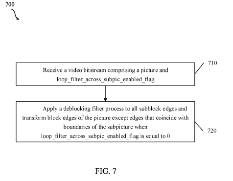
[0004] A first aspect relates to a method implemented by a video decoder
and comprising:
receiving, by the video decoder, a video bitstream comprising a picture and
loop filter across subpic enabled flag, wherein the picture comprises a
subpicture; and
applying a deblocking filter process to all subblock edges and transform block
edges of the
1
CA 03155886 2022-03-24
WO 2021/061826 PCT/US2020/052287
picture except edges that coincide with boundaries of the subpicture when
loop filter across subpic enabled flag is equal to 0.
[0005]
In a first embodiment, when two subpictures are adjacent to each other (e.g.,
the right
boundary of the first subpicture is also the left boundary of the second
subpicture or the bottom
boundary of the first subpicture is also the top boundary of the second
subpicture), and the values
of loop filter across subpic enabled flag[ i ] of the two subpictures are
different, two
conditions apply to deblocking of the boundary shared by the two subpictures.
First, for the
subpicture with loop filter across subpic enabled flag[ i] equal to 0,
deblocking is not applied
to the blocks at the boundary shared with the adjacent subpicture. Second, for
the subpicture
with loop filter across subpic enabled flag[ i ] equal to 1, deblocking is
applied to the blocks
at the boundary shared with the adjacent subpicture. To implement that
deblocking, boundary
strength determination is applied per the normal deblocking process, and
sample filtering is
applied only to samples belonging to the subpicture
with
loop filter across subpic enabled flag[ i] equal to 1. In a second embodiment,
when there is a
subpicture with the value of subpic treated as_pic flag[ i ] equal to 1 and
loop filter across subpic enabled flag[ i ] equal to 0,
the value of
loop filter across subpic enabled flag[ i ] of all subpictures shall be equal
to 0. In a third
embodiment, instead of signaling loop filter across subpic enabled flag[ i ]
for each
subpicture, only one flag is signaled to specify whether or not loop filter
across subpictures is
enabled. The disclosed embodiments reduce or eliminate the artifacts described
above and result
in fewer wasted bits in the encoded bitstream
[0006]
Optionally, in any of the preceding aspects, loop filter across subpic enabled
flag
equal to 1 specifies that in-loop filtering operations may be performed across
boundaries of a
subpicture in each coded picture in a CVS.
[0007]
Optionally, in any of the preceding aspects, loop filter across subpic enabled
flag
equal to 0 specifies that in-loop filtering operations are not performed
across boundaries of a
subpicture in each coded picture in a CVS.
[0008]
A second aspect relates to A method implemented by a video encoder and
comprising: generating, by the video encoder, loop filter across subpic
enabled flag so that a
deblocking filter process is applied to all subblock edges and transform block
edges of a picture
except edges that coincide with boundaries of a subpicture when
2
CA 03155886 2022-03-24
WO 2021/061826 PCT/US2020/052287
loop filter across subpic enabled flag is equal to 0; encoding, by the video
encoder,
loop filter across subpic enabled flag into a video bitstream; and storing, by
the video
encoder, the video bitstream for communication toward a video decoder.
[0009]
Optionally, in any of the preceding aspects, loop filter across subpic enabled
flag
equal to 1 specifies that in-loop filtering operations may be performed across
boundaries of a
subpicture in each coded picture in a CVS.
[0010]
Optionally, in any of the preceding aspects, loop filter across subpic enabled
flag
equal to 0 specifies that in-loop filtering operations are not performed
across boundaries of a
subpicture in each coded picture in a CVS.
[0011]
Optionally, in any of the preceding aspects, the method further comprises
generating
seq_parameter set rbsp; including loop
filter across subpic enabled flag in
seq_parameter set rbsp; and further encoding loop filter across subpic enabled
flag into the
video bitstream by encoding seq_parameter set rbsp into the video bitstream.
[0012]
A third aspect relates to a method implemented by a video decoder and
comprising:
receiving, by the video decoder, a video bitstream comprising a picture, EDGE
VER, and
loop filter across subpic enabled flag, wherein the picture comprises a
subpicture; and setting
filterEdgeFlag to 0 if edgeType is equal to the EDGE VER, a left boundary of a
current coding
block is a left boundary of the subpicture, and the loop filter across subpic
enabled flag is
equal to 0.
[0013]
Optionally, in any of the preceding aspects, the edgeType is a variable
specifying
whether a vertical edge or a horizontal edge is filtered.
[0014]
Optionally, in any of the preceding aspects, the edgeType equal to 0 specifies
that the
vertical edge is filtered, and wherein the EDGE VER is the vertical edge.
[0015]
Optionally, in any of the preceding aspects, the edgeType equal to 1 specifies
that the
horizontal edge is filtered, and wherein the EDGE HOR is the horizontal edge.
[0016] Optionally, in any of the preceding aspects,
the
loop filter across subpic enabled flag equal to 0 specifies that in-loop
filtering operations are
not performed across boundaries of a subpicture in each coded picture in a
CVS.
[0017]
Optionally, in any of the preceding aspects, the method further comprises
filtering the
picture based on the filterEdgeFlag.
3
CA 03155886 2022-03-24
WO 2021/061826 PCT/US2020/052287
[0018] A fourth aspect relates to a method implemented by a video decoder
and comprising:
receiving, by the video decoder, a video bitstream comprising a picture, EDGE
HOR, and
loop filter across subpic enabled flag, wherein the picture comprises a
subpicture; and setting
filterEdgeFlag to 0 if edgeType is equal to the EDGE HOR, a top boundary of a
current coding
block is a top boundary of the subpicture, and the loop filter across subpic
enabled flag is
equal to 0.
[0019] Optionally, in any of the preceding aspects, the edgeType is a
variable specifying
whether a vertical edge or a horizontal edge is filtered.
[0020] Optionally, in any of the preceding aspects, the edgeType equal to 0
specifies that the
vertical edge is filtered, and wherein the EDGE VER is the vertical edge.
[0021] Optionally, in any of the preceding aspects, the edgeType equal to 1
specifies that the
horizontal edge is filtered, and wherein the EDGE HOR is the horizontal edge.
[0022] Optionally, in any of the preceding aspects,
the
loop filter across subpic enabled flag equal to 0 specifies that in-loop
filtering operations are
not performed across boundaries of a subpicture in each coded picture in a
CVS.
[0023] Optionally, in any of the preceding aspects, the method further
comprises filtering the
picture based on the filterEdgeFlag.
[0024] A fifth aspect relates to a method implemented by a video decoder
and comprising:
receiving, by the video decoder, a video bitstream comprising a picture and
loop filter across subpic enabled flag, wherein the picture comprises a
subpicture; and
applying an SAO process to all subblock edges and transform block edges of the
picture except
edges that coincide with boundaries of the subpicture
when
loop filter across subpic enabled flag is equal to 0.
[0025] A sixth aspect relates to a method implemented by a video decoder
and comprising:
receiving, by the video decoder, a video bitstream comprising a picture and
loop filter across subpic enabled flag, wherein the picture comprises a
subpicture; and
applying an ALF process to all subblock edges and transform block edges of the
picture except
edges that coincide with boundaries of the subpicture
when
loop filter across subpic enabled flag is equal to 0.
[0026] Any of the above embodiments may be combined with any of the other
above
embodiments to create a new embodiment. These and other features will be more
clearly
4
CA 03155886 2022-03-24
WO 2021/061826 PCT/US2020/052287
understood from the following detailed description taken in conjunction with
the accompanying
drawings and claims.
BRIEF DESCRIPTION OF THE DRAWINGS
[0027] For a more complete understanding of this disclosure, reference is
now made to the
following brief description, taken in connection with the accompanying
drawings and detailed
description, wherein like reference numerals represent like parts.
[0028] FIG. 1 is a flowchart of an example method of coding a video signal.
[0029] FIG. 2 is a schematic diagram of an example coding and decoding
(codec) system for
video coding.
[0030] FIG. 3 is a schematic diagram illustrating an example video encoder.
[0031] FIG. 4 is a schematic diagram illustrating an example video decoder.
[0032] FIG. 5 is a schematic diagram illustrating a plurality of sub-
picture video streams
extracted from a picture video stream.
[0033] FIG. 6 is a schematic diagram illustrating an example bitstream
split into a sub-
bitstream.
[0034] FIG. 7 is a flowchart illustrating a method of decoding a bitstream
according to a first
embodiment.
[0035] FIG. 8 is a flowchart illustrating a method of encoding a bitstream
according to a first
embodiment.
[0036] FIG. 9 is a flowchart illustrating a method of decoding a bitstream
according to a
second embodiment.
[0037] FIG. 10 is a flowchart illustrating a method of decoding a bitstream
according to a
third embodiment.
[0038] FIG. 11 is a schematic diagram of a video coding device.
[0039] FIG. 12 is a schematic diagram of an embodiment of a means for
coding.
DETAILED DESCRIPTION
[0040] It should be understood at the outset that, although an illustrative
implementation of
one or more embodiments are provided below, the disclosed systems and/or
methods may be
implemented using any number of techniques, whether currently known or in
existence. The
CA 03155886 2022-03-24
WO 2021/061826 PCT/US2020/052287
disclosure should in no way be limited to the illustrative implementations,
drawings, and
techniques illustrated below, including the exemplary designs and
implementations illustrated
and described herein, but may be modified within the scope of the appended
claims along with
their full scope of equivalents.
[0041] The following abbreviations apply:
ALF: adaptive loop filter
ASIC: application-specific integrated circuit
AU: access unit
AUD: access unit delimiter
BT: binary tree
CABAC: context-adaptive binary arithmetic coding
CAVLC: context-adaptive variable-length coding
Cb: blue difference chroma
CPU: central processing unit
Cr: red difference chroma
CTB: coding tree block
CTU: coding tree unit
CU: coding unit
CVS: coded video sequence
DC: direct current
DCT: discrete cosine transform
DMNI: depth modeling mode
DPB: decoded picture buffer
DSP: digital signal processor
DST: discrete sine transform
EO: electrical-to-optical
FPGA: field-programmable gate array
HEVC: High Efficiency Video Coding
HMD: head-mounted display
I/O: input/output
NAL: network abstraction layer
6
CA 03155886 2022-03-24
WO 2021/061826 PCT/US2020/052287
OE: optical-to-electrical
PIPE: probability interval partitioning entropy
POC: picture order count
PPS: picture parameter set
PU: picture unit
QT: quad tree
RAM: random-access memory
RBSP: raw byte sequence payload
RDO: rate-distortion optimization
ROM: read-only memory
RPL: reference picture list
Rx: receiver unit
SAD: sum of absolute differences
SAO: sample adaptive offset
SBAC: syntax-based arithmetic coding
SPS: sequence parameter set
SRAM: static RAM
SSD: sum of squared differences
TCAM: ternary content-addressable memory
TT: triple tree
TU: transform unit
Tx: transmitter unit
VR: virtual reality
VVC: Versatile Video Coding.
[0042] The following definitions apply unless modified elsewhere: A
bitstream is a sequence
of bits including video data that is compressed for transmission between an
encoder and a
decoder. An encoder is a device that employs encoding processes to compress
video data into a
bitstream. A decoder is a device that employs decoding processes to
reconstruct video data from
a bitstream for display. A picture is an array of luma samples or chroma
samples that creates a
frame or a field. A picture that is being encoded or decoded can be referred
to as a current
picture. A reference picture contains reference samples that can be used when
coding other
7
CA 03155886 2022-03-24
WO 2021/061826 PCT/US2020/052287
pictures by reference according to inter-prediction or inter-layer prediction.
A reference picture
list is a list of reference pictures used for inter-prediction or inter-layer
prediction. A flag is a
variable or single-bit syntax element that can take one of the two possible
values: 0 or 1. Some
video coding systems utilize two reference picture lists, which can be denoted
as reference
picture list one and reference picture list zero. A reference picture list
structure is an addressable
syntax structure that contains multiple reference picture lists. Inter-
prediction is a mechanism of
coding samples of a current picture by reference to indicated samples in a
reference picture that
is different from the current picture, where the reference picture and the
current picture are in the
same layer. A reference picture list structure entry is an addressable
location in a reference
picture list structure that indicates a reference picture associated with a
reference picture list. A
slice header is a part of a coded slice containing data elements pertaining to
all video data within
a tile represented in the slice. A PPS contains data related to an entire
picture. More
specifically, the PPS is a syntax structure containing syntax elements that
apply to zero or more
entire coded pictures as determined by a syntax element found in each picture
header. An SPS
contains data related to a sequence of pictures. An AU is a set of one or more
coded pictures
associated with the same display time (e.g., the same picture order count) for
output from a DPB
(e.g., for display to a user). An AUD indicates the start of an AU or the
boundary between AUs.
A decoded video sequence is a sequence of pictures that have been
reconstructed by a decoder in
preparation for display to a user.
[0043] FIG. 1 is a flowchart of an example operating method 100 of coding a
video signal.
Specifically, a video signal is encoded at an encoder. The encoding process
compresses the
video signal by employing various mechanisms to reduce the video file size. A
smaller file size
allows the compressed video file to be transmitted toward a user, while
reducing associated
bandwidth overhead. The decoder then decodes the compressed video file to
reconstruct the
original video signal for display to an end user. The decoding process
generally mirrors the
encoding process to allow the decoder to consistently reconstruct the video
signal.
[0044] At step 101, the video signal is input into the encoder. For
example, the video signal
may be an uncompressed video file stored in memory. As another example, the
video file may
be captured by a video capture device, such as a video camera, and encoded to
support live
streaming of the video. The video file may include both an audio component and
a video
component. The video component contains a series of image frames that, when
viewed in a
8
CA 03155886 2022-03-24
WO 2021/061826 PCT/US2020/052287
sequence, gives the visual impression of motion. The frames contain pixels
that are expressed in
terms of light, referred to herein as luma components (or luma samples), and
color, which is
referred to as chroma components (or color samples). In some examples, the
frames may also
contain depth values to support three dimensional viewing.
[0045] At step 103, the video is partitioned into blocks. Partitioning
includes subdividing the
pixels in each frame into square and/or rectangular blocks for compression.
For example, in
HEVC, the frame can first be divided into CTUs, which are blocks of a
predefined size (e.g.,
sixty-four pixels by sixty-four pixels). The CTUs contain both luma and chroma
samples.
Coding trees may be employed to divide the CTUs into blocks and then
recursively subdivide the
blocks until configurations are achieved that support further encoding. For
example, luma
components of a frame may be subdivided until the individual blocks contain
relatively
homogenous lighting values. Further, chroma components of a frame may be
subdivided until
the individual blocks contain relatively homogenous color values. Accordingly,
partitioning
mechanisms vary depending on the content of the video frames.
[0046] At step 105, various compression mechanisms are employed to compress
the image
blocks partitioned at step 103. For example, inter-prediction and/or intra-
prediction may be
employed. Inter-prediction is designed to take advantage of the fact that
objects in a common
scene tend to appear in successive frames. Accordingly, a block depicting an
object in a
reference frame need not be repeatedly described in adjacent frames.
Specifically, an object,
such as a table, may remain in a constant position over multiple frames. Hence
the table is
described once and adjacent frames can refer back to the reference frame.
Pattern matching
mechanisms may be employed to match objects over multiple frames. Further,
moving objects
may be represented across multiple frames, for example due to object movement
or camera
movement. As a particular example, a video may show an automobile that moves
across the
screen over multiple frames. Motion vectors can be employed to describe such
movement. A
motion vector is a two-dimensional vector that provides an offset from the
coordinates of an
object in a frame to the coordinates of the object in a reference frame. As
such, inter-prediction
can encode an image block in a current frame as a set of motion vectors
indicating an offset from
a corresponding block in a reference frame.
[0047] Intra-prediction encodes blocks in a common frame. Intra-prediction
takes advantage
of the fact that luma and chroma components tend to cluster in a frame. For
example, a patch of
9
CA 03155886 2022-03-24
WO 2021/061826 PCT/US2020/052287
green in a portion of a tree tends to be positioned adjacent to similar
patches of green. Intra-
prediction employs multiple directional prediction modes (e.g., 33 in HEVC), a
planar mode, and
a DC mode. The directional modes indicate that a current block is similar/the
same as samples
of a neighbor block in a corresponding direction. Planar mode indicates that a
series of blocks
along a row/column (e.g., a plane) can be interpolated based on neighbor
blocks at the edges of
the row. Planar mode, in effect, indicates a smooth transition of light/color
across a row/column
by employing a relatively constant slope in changing values. DC mode is
employed for
boundary smoothing and indicates that a block is similar/the same as an
average value associated
with samples of all the neighbor blocks associated with the angular directions
of the directional
prediction modes. Accordingly, intra-prediction blocks can represent image
blocks as various
relational prediction mode values instead of the actual values. Further, inter-
prediction blocks
can represent image blocks as motion vector values instead of the actual
values. In either case,
the prediction blocks may not exactly represent the image blocks in some
cases. Any differences
are stored in residual blocks. Transforms may be applied to the residual
blocks to further
compress the file.
[0048] At step 107, various filtering techniques may be applied. In HEVC,
the filters are
applied according to an in-loop filtering scheme. The block based prediction
discussed above
may result in the creation of blocky images at the decoder. Further, the block
based prediction
scheme may encode a block and then reconstruct the encoded block for later use
as a reference
block. The in-loop filtering scheme iteratively applies noise suppression
filters, de-blocking
filters, adaptive loop filters, and SAO filters to the blocks/frames. These
filters mitigate such
blocking artifacts so that the encoded file can be accurately reconstructed.
Further, these filters
mitigate artifacts in the reconstructed reference blocks so that artifacts are
less likely to create
additional artifacts in subsequent blocks that are encoded based on the
reconstructed reference
blocks.
[0049] Once the video signal has been partitioned, compressed, and
filtered, the resulting
data is encoded in a bitstream at step 109. The bitstream includes the data
discussed above as
well as any signaling data desired to support proper video signal
reconstruction at the decoder.
For example, such data may include partition data, prediction data, residual
blocks, and various
flags providing coding instructions to the decoder. The bitstream may be
stored in memory for
transmission toward a decoder upon request. The bitstream may also be
broadcast and/or
CA 03155886 2022-03-24
WO 2021/061826 PCT/US2020/052287
multicast toward a plurality of decoders. The creation of the bitstream is an
iterative process.
Accordingly, steps 101, 103, 105, 107, and 109 may occur continuously and/or
simultaneously
over many frames and blocks. The order shown in FIG. 1 is presented for
clarity and ease of
discussion, and is not intended to limit the video coding process to a
particular order.
[0050] The decoder receives the bitstream and begins the decoding process
at step 111.
Specifically, the decoder employs an entropy decoding scheme to convert the
bitstream into
corresponding syntax and video data. The decoder employs the syntax data from
the bitstream to
determine the partitions for the frames at step 111. The partitioning should
match the results of
block partitioning at step 103. Entropy encoding/decoding as employed in step
111 is now
described. The encoder makes many choices during the compression process, such
as selecting
block partitioning schemes from several possible choices based on the spatial
positioning of
values in the input image(s). Signaling the exact choices may employ a large
number of bins.
As used herein, a bin is a binary value that is treated as a variable (e.g., a
bit value that may vary
depending on context). Entropy coding allows the encoder to discard any
options that are clearly
not viable for a particular case, leaving a set of allowable options. Each
allowable option is then
assigned a code word. The length of the code words is based on the number of
allowable options
(e.g., one bin for two options, two bins for three to four options, etc.) The
encoder then encodes
the code word for the selected option. This scheme reduces the size of the
code words as the
code words are as big as desired to uniquely indicate a selection from a small
sub-set of
allowable options as opposed to uniquely indicating the selection from a
potentially large set of
all possible options. The decoder then decodes the selection by determining
the set of allowable
options in a similar manner to the encoder. By determining the set of
allowable options, the
decoder can read the code word and determine the selection made by the
encoder.
[0051] At step 113, the decoder performs block decoding. Specifically, the
decoder employs
reverse transforms to generate residual blocks. Then the decoder employs the
residual blocks
and corresponding prediction blocks to reconstruct the image blocks according
to the
partitioning. The prediction blocks may include both intra-prediction blocks
and inter-prediction
blocks as generated at the encoder at step 105. The reconstructed image blocks
are then
positioned into frames of a reconstructed video signal according to the
partitioning data
determined at step 111. Syntax for step 113 may also be signaled in the
bitstream via entropy
coding as discussed above.
11
CA 03155886 2022-03-24
WO 2021/061826 PCT/US2020/052287
[0052] At step 115, filtering is performed on the frames of the
reconstructed video signal in a
manner similar to step 107 at the encoder. For example, noise suppression
filters, de-blocking
filters, adaptive loop filters, and SAO filters may be applied to the frames
to remove blocking
artifacts. Once the frames are filtered, the video signal can be output to a
display at step 117 for
viewing by an end user.
[0053] FIG. 2 is a schematic diagram of an example coding and decoding
(codec) system
200 for video coding. Specifically, codec system 200 provides functionality to
support the
implementation of operating method 100. Codec system 200 is generalized to
depict
components employed in both an encoder and a decoder. Codec system 200
receives and
partitions a video signal as discussed with respect to steps 101 and 103 in
operating method 100,
which results in a partitioned video signal 201. Codec system 200 then
compresses the
partitioned video signal 201 into a coded bitstream when acting as an encoder
as discussed with
respect to steps 105, 107, and 109 in method 100. When acting as a decoder,
codec system 200
generates an output video signal from the bitstream as discussed with respect
to steps 111, 113,
115, and 117 in operating method 100. The codec system 200 includes a general
coder control
component 211, a transform scaling and quantization component 213, an intra-
picture estimation
component 215, an intra-picture prediction component 217, a motion
compensation component
219, a motion estimation component 221, a scaling and inverse transform
component 229, a filter
control analysis component 227, an in-loop filters component 225, a decoded
picture buffer
component 223, and a header formatting and CABAC component 231. Such
components are
coupled as shown. In FIG. 2, black lines indicate movement of data to be
encoded/decoded
while dashed lines indicate movement of control data that controls the
operation of other
components. The components of codec system 200 may all be present in the
encoder. The
decoder may include a subset of the components of codec system 200. For
example, the decoder
may include the intra-picture prediction component 217, the motion
compensation component
219, the scaling and inverse transform component 229, the in-loop filters
component 225, and
the decoded picture buffer component 223. These components are now described.
[0054] The partitioned video signal 201 is a captured video sequence that
has been
partitioned into blocks of pixels by a coding tree. A coding tree employs
various split modes to
subdivide a block of pixels into smaller blocks of pixels. These blocks can
then be further
subdivided into smaller blocks. The blocks may be referred to as nodes on the
coding tree.
12
CA 03155886 2022-03-24
WO 2021/061826 PCT/US2020/052287
Larger parent nodes are split into smaller child nodes. The number of times a
node is subdivided
is referred to as the depth of the node/coding tree. The divided blocks can be
included in CUs in
some cases. For example, a CU can be a sub-portion of a CTU that contains a
luma block, Cr
block(s), and a Cb block(s) along with corresponding syntax instructions for
the CU. The split
modes may include a BT, TT, and QT employed to partition a node into two,
three, or four child
nodes, respectively, of varying shapes depending on the split modes employed.
The partitioned
video signal 201 is forwarded to the general coder control component 211, the
transform scaling
and quantization component 213, the intra-picture estimation component 215,
the filter control
analysis component 227, and the motion estimation component 221 for
compression.
[0055] The general coder control component 211 is configured to make
decisions related to
coding of the images of the video sequence into the bitstream according to
application
constraints. For example, the general coder control component 211 manages
optimization of
bitrate/bitstream size versus reconstruction quality. Such decisions may be
made based on
storage space/bandwidth availability and image resolution requests. The
general coder control
component 211 also manages buffer utilization in light of transmission speed
to mitigate buffer
underrun and overrun issues. To manage these issues, the general coder control
component 211
manages partitioning, prediction, and filtering by the other components. For
example, the general
coder control component 211 may dynamically increase compression complexity to
increase
resolution and increase bandwidth usage or decrease compression complexity to
decrease
resolution and bandwidth usage. Hence, the general coder control component 211
controls the
other components of codec system 200 to balance video signal reconstruction
quality with bit
rate concerns. The general coder control component 211 creates control data,
which controls the
operation of the other components. The control data is also forwarded to the
header formatting
and CABAC component 231 to be encoded in the bitstream to signal parameters
for decoding at
the decoder.
[0056] The partitioned video signal 201 is also sent to the motion
estimation component 221
and the motion compensation component 219 for inter-prediction. A frame or
slice of the
partitioned video signal 201 may be divided into multiple video blocks. Motion
estimation
component 221 and the motion compensation component 219 perform inter-
predictive coding of
the received video block relative to one or more blocks in one or more
reference frames to
13
CA 03155886 2022-03-24
WO 2021/061826 PCT/US2020/052287
provide temporal prediction. Codec system 200 may perform multiple coding
passes, e.g., to
select an appropriate coding mode for each block of video data.
[0057] Motion estimation component 221 and motion compensation component
219 may be
highly integrated, but are illustrated separately for conceptual purposes.
Motion estimation,
performed by motion estimation component 221, is the process of generating
motion vectors,
which estimate motion for video blocks. A motion vector, for example, may
indicate the
displacement of a coded object relative to a predictive block. A predictive
block is a block that
is found to closely match the block to be coded, in terms of pixel difference.
A predictive block
may also be referred to as a reference block. Such pixel difference may be
determined by an
SAD, an SSD, or other difference metrics. HEVC employs several coded objects
including a
CTU, CTBs, and CUs. For example, a CTU can be divided into CTBs, which can
then be
divided into CBs for inclusion in CUs. A CU can be encoded as a prediction
unit containing
prediction data and/or a TU containing transformed residual data for the CU.
The motion
estimation component 221 generates motion vectors, prediction units, and TUs
by using a rate-
distortion analysis as part of a rate distortion optimization process. For
example, the motion
estimation component 221 may determine multiple reference blocks, multiple
motion vectors,
etc. for a current block/frame, and may select the reference blocks, motion
vectors, etc. having
the best rate-distortion characteristics. The best rate-distortion
characteristics balance both
quality of video reconstruction (e.g., amount of data loss by compression)
with coding efficiency
(e.g., size of the final encoding).
[0058] In some examples, codec system 200 may calculate values for sub-
integer pixel
positions of reference pictures stored in decoded picture buffer component
223. For example,
video codec system 200 may interpolate values of one-quarter pixel positions,
one-eighth pixel
positions, or other fractional pixel positions of the reference picture.
Therefore, motion
estimation component 221 may perform a motion search relative to the full
pixel positions and
fractional pixel positions and output a motion vector with fractional pixel
precision. The motion
estimation component 221 calculates a motion vector for a prediction unit of a
video block in an
inter-coded slice by comparing the position of the prediction unit to the
position of a predictive
block of a reference picture. Motion estimation component 221 outputs the
calculated motion
vector as motion data to header formatting and CABAC component 231 for
encoding and motion
to the motion compensation component 219.
14
CA 03155886 2022-03-24
WO 2021/061826 PCT/US2020/052287
[0059] Motion compensation, performed by motion compensation component 219,
may
involve fetching or generating the predictive block based on the motion vector
determined by
motion estimation component 221. Again, motion estimation component 221 and
motion
compensation component 219 may be functionally integrated, in some examples.
Upon receiving
the motion vector for the prediction unit of the current video block, motion
compensation
component 219 may locate the predictive block to which the motion vector
points. A residual
video block is then formed by subtracting pixel values of the predictive block
from the pixel
values of the current video block being coded, forming pixel difference
values. In general,
motion estimation component 221 performs motion estimation relative to luma
components, and
motion compensation component 219 uses motion vectors calculated based on the
luma
components for both chroma components and luma components. The predictive
block and
residual block are forwarded to transform scaling and quantization component
213.
[0060] The partitioned video signal 201 is also sent to intra-picture
estimation component
215 and intra-picture prediction component 217. As with motion estimation
component 221 and
motion compensation component 219, intra-picture estimation component 215 and
intra-picture
prediction component 217 may be highly integrated, but are illustrated
separately for conceptual
purposes. The intra-picture estimation component 215 and intra-picture
prediction component
217 intra-predict a current block relative to blocks in a current frame, as an
alternative to the
inter-prediction performed by motion estimation component 221 and motion
compensation
component 219 between frames, as described above. In particular, the intra-
picture estimation
component 215 determines an intra-prediction mode to use to encode a current
block. In some
examples, intra-picture estimation component 215 selects an appropriate intra-
prediction mode to
encode a current block from multiple tested intra-prediction modes. The
selected intra-prediction
modes are then forwarded to the header formatting and CABAC component 231 for
encoding.
[0061] For example, the intra-picture estimation component 215 calculates
rate-distortion
values using a rate-distortion analysis for the various tested intra-
prediction modes, and selects
the intra-prediction mode having the best rate-distortion characteristics
among the tested modes.
Rate-distortion analysis generally determines an amount of distortion (or
error) between an
encoded block and an original un-encoded block that was encoded to produce the
encoded block,
as well as a bitrate (e.g., a number of bits) used to produce the encoded
block. The intra-picture
estimation component 215 calculates ratios from the distortions and rates for
the various encoded
CA 03155886 2022-03-24
WO 2021/061826 PCT/US2020/052287
blocks to determine which intra-prediction mode exhibits the best rate-
distortion value for the
block. In addition, intra-picture estimation component 215 may be configured
to code depth
blocks of a depth map using a DMM based on RDO.
[0062] The intra-picture prediction component 217 may generate a residual
block from the
predictive block based on the selected intra-prediction modes determined by
intra-picture
estimation component 215 when implemented on an encoder or read the residual
block from the
bitstream when implemented on a decoder. The residual block includes the
difference in values
between the predictive block and the original block, represented as a matrix.
The residual block
is then forwarded to the transform scaling and quantization component 213. The
intra-picture
estimation component 215 and the intra-picture prediction component 217 may
operate on both
luma and chroma components.
[0063] The transform scaling and quantization component 213 is configured
to further
compress the residual block. The transform scaling and quantization component
213 applies a
transform, such as a DCT, a DST, or a conceptually similar transform, to the
residual block,
producing a video block comprising residual transform coefficient values.
Wavelet transforms,
integer transforms, sub-band transforms or other types of transforms could
also be used. The
transform may convert the residual information from a pixel value domain to a
transform
domain, such as a frequency domain. The transform scaling and quantization
component 213 is
also configured to scale the transformed residual information, for example
based on frequency.
Such scaling involves applying a scale factor to the residual information so
that different
frequency information is quantized at different granularities, which may
affect final visual
quality of the reconstructed video. The transform scaling and quantization
component 213 is
also configured to quantize the transform coefficients to further reduce bit
rate. The quantization
process may reduce the bit depth associated with some or all of the
coefficients. The degree of
quantization may be modified by adjusting a quantization parameter. In some
examples, the
transform scaling and quantization component 213 may then perform a scan of
the matrix
including the quantized transform coefficients. The quantized transform
coefficients are
forwarded to the header formatting and CABAC component 231 to be encoded in
the bitstream.
[0064] The scaling and inverse transform component 229 applies a reverse
operation of the
transform scaling and quantization component 213 to support motion estimation.
The scaling
and inverse transform component 229 applies inverse scaling, transformation,
and/or
16
CA 03155886 2022-03-24
WO 2021/061826 PCT/US2020/052287
quantization to reconstruct the residual block in the pixel domain, e.g., for
later use as a reference
block which may become a predictive block for another current block. The
motion estimation
component 221 and/or motion compensation component 219 may calculate a
reference block by
adding the residual block back to a corresponding predictive block for use in
motion estimation
of a later block/frame. Filters are applied to the reconstructed reference
blocks to mitigate
artifacts created during scaling, quantization, and transform. Such artifacts
could otherwise
cause inaccurate prediction (and create additional artifacts) when subsequent
blocks are
predicted.
[0065] The filter control analysis component 227 and the in-loop filters
component 225
apply the filters to the residual blocks and/or to reconstructed image blocks.
For example, the
transformed residual block from the scaling and inverse transform component
229 may be
combined with a corresponding prediction block from intra-picture prediction
component 217
and/or motion compensation component 219 to reconstruct the original image
block. The filters
may then be applied to the reconstructed image block. In some examples, the
filters may instead
be applied to the residual blocks. As with other components in FIG. 2, the
filter control analysis
component 227 and the in-loop filters component 225 are highly integrated and
may be
implemented together, but are depicted separately for conceptual purposes.
Filters applied to the
reconstructed reference blocks are applied to particular spatial regions and
include multiple
parameters to adjust how such filters are applied. The filter control analysis
component 227
analyzes the reconstructed reference blocks to determine where such filters
should be applied
and sets corresponding parameters. Such data is forwarded to the header
formatting and CABAC
component 231 as filter control data for encoding. The in-loop filters
component 225 applies
such filters based on the filter control data. The filters may include a de-
blocking filter, a noise
suppression filter, an SAO filter, and an adaptive loop filter. Such filters
may be applied in the
spatial/pixel domain (e.g., on a reconstructed pixel block) or in the
frequency domain, depending
on the example.
[0066] When operating as an encoder, the filtered reconstructed image
block, residual block,
and/or prediction block are stored in the decoded picture buffer component 223
for later use in
motion estimation as discussed above. When operating as a decoder, the decoded
picture buffer
component 223 stores and forwards the reconstructed and filtered blocks toward
a display as part
17
CA 03155886 2022-03-24
WO 2021/061826 PCT/US2020/052287
of an output video signal. The decoded picture buffer component 223 may be any
memory
device capable of storing prediction blocks, residual blocks, and/or
reconstructed image blocks.
[0067] The header formatting and CABAC component 231 receives the data from
the
various components of codec system 200 and encodes such data into a coded
bitstream for
transmission toward a decoder. Specifically, the header formatting and CABAC
component 231
generates various headers to encode control data, such as general control data
and filter control
data. Further, prediction data, including intra-prediction and motion data, as
well as residual data
in the form of quantized transform coefficient data are all encoded in the
bitstream. The final
bitstream includes all information desired by the decoder to reconstruct the
original partitioned
video signal 201. Such information may also include intra-prediction mode
index tables (also
referred to as codeword mapping tables), definitions of encoding contexts for
various blocks,
indications of most probable intra-prediction modes, an indication of
partition information, etc.
Such data may be encoded by employing entropy coding. For example, the
information may be
encoded by employing CAVLC, CABAC, SBAC, PIPE coding, or another entropy
coding
technique. Following the entropy coding, the coded bitstream may be
transmitted to another
device (e.g., a video decoder) or archived for later transmission or
retrieval.
[0068] FIG. 3 is a block diagram illustrating an example video encoder 300.
Video encoder
300 may be employed to implement the encoding functions of codec system 200
and/or
implement steps 101, 103, 105, 107, and/or 109 of operating method 100.
Encoder 300
partitions an input video signal, resulting in a partitioned video signal 301,
which is substantially
similar to the partitioned video signal 201. The partitioned video signal 301
is then compressed
and encoded into a bitstream by components of encoder 300.
[0069] Specifically, the partitioned video signal 301 is forwarded to an
intra-picture
prediction component 317 for intra-prediction. The intra-picture prediction
component 317 may
be substantially similar to intra-picture estimation component 215 and intra-
picture prediction
component 217. The partitioned video signal 301 is also forwarded to a motion
compensation
component 321 for inter-prediction based on reference blocks in a decoded
picture buffer
component 323. The motion compensation component 321 may be substantially
similar to
motion estimation component 221 and motion compensation component 219. The
prediction
blocks and residual blocks from the intra-picture prediction component 317 and
the motion
compensation component 321 are forwarded to a transform and quantization
component 313 for
18
CA 03155886 2022-03-24
WO 2021/061826 PCT/US2020/052287
transform and quantization of the residual blocks. The transform and
quantization component
313 may be substantially similar to the transform scaling and quantization
component 213. The
transformed and quantized residual blocks and the corresponding prediction
blocks (along with
associated control data) are forwarded to an entropy coding component 331 for
coding into a
bitstream. The entropy coding component 331 may be substantially similar to
the header
formatting and CABAC component 231.
[0070] The transformed and quantized residual blocks and/or the
corresponding prediction
blocks are also forwarded from the transform and quantization component 313 to
an inverse
transform and quantization component 329 for reconstruction into reference
blocks for use by the
motion compensation component 321. The inverse transform and quantization
component 329
may be substantially similar to the scaling and inverse transform component
229. In-loop filters
in an in-loop filters component 325 are also applied to the residual blocks
and/or reconstructed
reference blocks, depending on the example. The in-loop filters component 325
may be
substantially similar to the filter control analysis component 227 and the in-
loop filters
component 225. The in-loop filters component 325 may include multiple filters
as discussed
with respect to in-loop filters component 225. The filtered blocks are then
stored in a decoded
picture buffer component 323 for use as reference blocks by the motion
compensation
component 321. The decoded picture buffer component 323 may be substantially
similar to the
decoded picture buffer component 223.
[0071] FIG. 4 is a block diagram illustrating an example video decoder 400.
Video decoder
400 may be employed to implement the decoding functions of codec system 200
and/or
implement steps 111, 113, 115, and/or 117 of operating method 100. Decoder 400
receives a
bitstream, for example from an encoder 300, and generates a reconstructed
output video signal
based on the bitstream for display to an end user.
[0072] The bitstream is received by an entropy decoding component 433. The
entropy
decoding component 433 is configured to implement an entropy decoding scheme,
such as
CAVLC, CABAC, SBAC, PIPE coding, or other entropy coding techniques. For
example, the
entropy decoding component 433 may employ header information to provide a
context to
interpret additional data encoded as codewords in the bitstream. The decoded
information
includes any desired information to decode the video signal, such as general
control data, filter
control data, partition information, motion data, prediction data, and
quantized transform
19
CA 03155886 2022-03-24
WO 2021/061826 PCT/US2020/052287
coefficients from residual blocks. The quantized transform coefficients are
forwarded to an
inverse transform and quantization component 429 for reconstruction into
residual blocks. The
inverse transform and quantization component 429 may be similar to inverse
transform and
quantization component 329.
[0073] The reconstructed residual blocks and/or prediction blocks are
forwarded to intra-
picture prediction component 417 for reconstruction into image blocks based on
intra-prediction
operations. The intra-picture prediction component 417 may be similar to intra-
picture
estimation component 215 and an intra-picture prediction component 217.
Specifically, the
intra-picture prediction component 417 employs prediction modes to locate a
reference block in
the frame and applies a residual block to the result to reconstruct intra-
predicted image blocks.
The reconstructed intra-predicted image blocks and/or the residual blocks and
corresponding
inter-prediction data are forwarded to a decoded picture buffer component 423
via an in-loop
filters component 425, which may be substantially similar to decoded picture
buffer component
223 and in-loop filters component 225, respectively. The in-loop filters
component 425 filters
the reconstructed image blocks, residual blocks and/or prediction blocks, and
such information is
stored in the decoded picture buffer component 423. Reconstructed image blocks
from decoded
picture buffer component 423 are forwarded to a motion compensation component
421 for inter-
prediction. The motion compensation component 421 may be substantially similar
to motion
estimation component 221 and/or motion compensation component 219.
Specifically, the motion
compensation component 421 employs motion vectors from a reference block to
generate a
prediction block and applies a residual block to the result to reconstruct an
image block. The
resulting reconstructed blocks may also be forwarded via the in-loop filters
component 425 to the
decoded picture buffer component 423. The decoded picture buffer component 423
continues to
store additional reconstructed image blocks, which can be reconstructed into
frames via the
partition information. Such frames may also be placed in a sequence. The
sequence is output
toward a display as a reconstructed output video signal.
[0074] FIG. 5 is a schematic diagram illustrating a plurality of sub-
picture video streams
501, 502, and 503 extracted from a picture video stream 500. For example, each
of the sub-
picture video streams 501-503 or the picture video stream 500 may be encoded
by an encoder,
such as codec system 200 or encoder 300 according to method 100. Further, the
sub-picture
CA 03155886 2022-03-24
WO 2021/061826 PCT/US2020/052287
video streams 501-503 or the picture video stream 500 may be decoded by a
decoder such as
codec system 200 or decoder 400.
[0075] The picture video stream 500 includes a plurality of pictures
presented over time.
The picture video stream 500 is configured for use in VR applications. VR
operates by coding a
sphere of video content, which can be displayed as if the user is in the
center of the sphere. Each
picture includes the entire sphere. Meanwhile, only a portion of the picture,
known as a
viewport, is displayed to the user. For example, the user may employ an HMD
that selects and
displays a viewport of the sphere based on the user's head movement. This
provides the
impression of being physically present in a virtual space as depicted by the
video. In order to
accomplish this result, each picture of the video sequence includes an entire
sphere of video data
at a corresponding instant in time. However, only a small portion (e.g., a
single viewport) of the
picture is displayed to the user. The remainder of the picture is discarded at
the decoder without
being rendered. The entire picture may be transmitted so that a different
viewport can be
dynamically selected and displayed in response to the user's head movement.
[0076] The pictures of the picture video stream 500 can each be sub-divided
into sub-
pictures based on available viewports. Accordingly, each picture and
corresponding sub-picture
includes a temporal position (e.g., picture order) as part of the temporal
presentation. Sub-
picture video streams 501-503 are created when the sub-division is applied
consistently over
time. Such consistent sub-division creates sub-picture video streams 501-503
where each stream
contains a set of sub-pictures of a predetermined size, shape, and spatial
position relative to
corresponding pictures in the picture video stream 500. Further, the set of
sub-pictures in a sub-
picture video stream 501-503 varies in temporal position over the presentation
time. As such,
the sub-pictures of the sub-picture video streams 501-503 can be aligned in
the time domain
based on temporal position. Then the sub-pictures from the sub-picture video
streams 501-503 at
each temporal position can be merged in the spatial domain based on predefined
spatial position
to reconstruct the picture video stream 500 for display. Specifically, the sub-
picture video
streams 501-503 can each be encoded into separate sub-bitstreams. When such
sub-bitstreams
are merged together, they result in a bitstream that includes the entire set
of pictures over time.
The resulting bitstream can be transmitted toward the decoder for decoding and
display based on
the user's currently-selected viewport.
21
CA 03155886 2022-03-24
WO 2021/061826 PCT/US2020/052287
[0077] All of the sub-picture video streams 501-503 may be transmitted to a
user at a high
quality. This allows the decoder to dynamically select the user's current
viewport and display
the sub-pictures from the corresponding sub-picture video streams 501-503 in
real time.
However, the user may view only a single viewport, for example from sub-
picture video stream
501, while sub-picture video streams 502-503 are discarded. As such,
transmitting sub-picture
video streams 502-503 at a high quality may waste a significant amount of
bandwidth. In order
to improve coding efficiency, the VR video may be encoded into a plurality of
video streams 500
where each video stream 500 is encoded at a different quality. In this way,
the decoder can
transmit a request for a current sub-picture video stream 501. In response,
the encoder can select
the higher-quality sub-picture video stream 501 from the higher-quality video
stream 500 and the
lower-quality sub-picture video streams 502-503 from the lower-quality video
stream 500. The
encoder can then merge such sub-bitstreams together into a complete encoded
bitstream for
transmission to the decoder. In this way, the decoder receives a series of
pictures where the
current viewport is higher quality and the other viewports are lower quality.
Further, the highest-
quality sub-pictures are generally displayed to the user and the lower-quality
sub-pictures are
generally discarded, which balances functionality with coding efficiency.
[0078] In the event that the user turns from viewing the sub-picture video
stream 501 to the
sub-picture video stream 502, the decoder requests the new current sub-picture
video stream 502
be transmitted at the higher quality. The encoder can then alter the merging
mechanism
accordingly.
[0079] Sub-pictures may also be employed in teleconferencing systems. In
such a case, each
user's video feed is included in a sub-picture bitstream, such as sub-picture
video stream 501,
502, or 503. The system can receive such sub-picture video stream 501, 502, or
503 and
combine them in different positions or resolutions to create a complete
picture video stream 500
for transmission back to the users. This allows the teleconferencing system to
dynamically
change the picture video stream 500 based on changing user input, for example
by increasing or
decreasing the size of a sub-picture video stream 501, 502, or 503, to
emphasize users who are
currently speaking or deemphasize users who are no longer speaking.
Accordingly, sub-pictures
have many applications that allow a picture video stream 500 to be dynamically
altered at run-
time based on changes in user behavior. This functionality may be achieved by
extracting or
combining sub-picture video stream 501, 502, or 503 from or into the picture
video stream 500.
22
CA 03155886 2022-03-24
WO 2021/061826 PCT/US2020/052287
[0080] FIG. 6 is a schematic diagram illustrating an example bitstream 600
split into a sub-
bitstream 601. The bitstream 600 may contain a picture video stream such as
picture video
stream 500, and the sub-bitstream 601 may contain a sub-picture video stream
such as sub-
picture video stream 501, 502, or 503. For example, the bitstream 600 and the
sub-bitstream 601
can be generated by a codec system 200 or an encoder 300 for decoding by a
codec system 200
or a decoder 400. As another example, the bitstream 600 and the sub-bitstream
601 may be
generated by an encoder at step 109 of method 100 for use by a decoder at step
111.
[0081] The bitstream 600 includes an SPS 610, a plurality of PPSs 611, a
plurality of slice
headers 615, and image data 620. An SPS 610 contains sequence data common to
all the
pictures in the video sequence contained in the bitstream 600. Such data can
include picture
sizing, bit depth, coding tool parameters, or bit rate restrictions. The PPS
611 contains
parameters that apply to an entire picture. Hence, each picture in the video
sequence may refer
to a PPS 611. While each picture refers to a PPS 611, a single PPS 611 can
contain data for
multiple pictures. For example, multiple similar pictures may be coded
according to similar
parameters. In such a case, a single PPS 611 may contain data for such similar
pictures. The
PPS 611 can indicate coding tools available for slices in corresponding
pictures, quantization
parameters, or offsets. The slice header 615 contains parameters that are
specific to each slice in
a picture. Hence, there may be one slice header 615 per slice in the video
sequence. The slice
header 615 may contain slice type information, POCs, RPLs, prediction weights,
tile entry
points, or deblocking parameters. A slice header 615 may also be referred to
as a tile group
header. A bitstream 600 may also include a picture header, which is a syntax
structure that
contains parameters that apply to all slices in a single picture. For this
reason, a picture header
and a slice header 615 may be used interchangeably. For example, certain
parameters may be
moved between the slice header 615 and a picture header depending on whether
such parameters
are common to all slices in a picture.
[0082] The image data 620 contains video data encoded according to inter-
prediction, intra-
prediction, or inter-layer prediction, as well as corresponding transformed
and quantized residual
data. For example, a video sequence includes a plurality of pictures 621. A
picture 621 is an
array of luma samples or an array of chroma samples that create a frame or a
field thereof A
frame is a complete image that is intended for complete or partial display to
a user at a
corresponding instant in a video sequence. A picture 621 contains one or more
slices. A slice
23
CA 03155886 2022-03-24
WO 2021/061826 PCT/US2020/052287
may be defined as an integer number of complete tiles or an integer number of
consecutive
complete CTU rows (e.g., within a tile) of a picture 621 that are exclusively
contained in a single
NAL unit. The slices are further divided into CTUs or CTBs. A CTU is a group
of samples of a
predefined size that can be partitioned by a coding tree. A CTB is a subset of
a CTU and
contains luma components or chroma components of the CTU. The CTUs/CTBs are
further
divided into coding blocks based on coding trees.
The coding blocks can then be
encoded/decoded according to prediction mechanisms.
[0083]
A picture 621 can be split into a plurality of sub-pictures 623 and 624. A sub-
picture
623 or 624 is a rectangular region of one or more slices within a picture 621.
Hence, each of the
slices, and sub-divisions thereof, can be assigned to a sub-picture 623 or
624. This allows
different regions of the picture 621 to be treated differently from a coding
perspective depending
on which sub-picture 623 or 624 includes such regions.
[0084]
A sub-bitstream 601 can be extracted from the bitstream 600 according to a sub-
bitstream extraction process 605. A sub-bitstream extraction process 605 is a
specified
mechanism that removes NAL units from a bitstream that are not a part of a
target set resulting in
an output sub-bitstream that includes the NAL units that are included in the
target set. A NAL
unit contains a slice. As such, the sub-bitstream extraction process 605
retains a target set of
slices and removes other slices. The target set can be selected based on sub-
picture boundaries.
The slices in the sub-picture 623 are included in the target set and the
slices in the sub-picture
624 are not included in the target set. As such, the sub-bitstream extraction
process 605 creates a
sub-bitstream 601 that is substantially similar to bitstream 600, but contains
the sub-picture 623,
while excluding the sub-picture 624. A sub-bitstream extraction process 605
may be performed
by an encoder or an associated slicer configured to dynamically alter a
bitstream 600 based on
user behavior/requests.
[0085]
Accordingly, the sub-bitstream 601 is an extracted bitstream that is a result
of a sub-
bitstream extraction process 605 applied to an input bitstream 600. The input
bitstream 600
contains a set of sub-pictures. However, the extracted bitstream (e.g., sub-
bitstream 601)
contains only a subset of the sub-pictures of the input bitstream 600 to the
sub-bitstream
extraction process 605. The set of sub-pictures in the input bitstream 600
includes sub-pictures
623 and 624, while the sub-set of the sub-pictures in the sub-bitstream 601
includes sub-picture
623 but not sub-picture 624. Any number of sub-pictures 623-624 can be
employed. For
24
CA 03155886 2022-03-24
WO 2021/061826 PCT/US2020/052287
example, the bitstream 600 may include N sub-pictures 623-624 and the sub-
bitstream may
contain N-1 or fewer sub-pictures 623, where N is any integer value.
[0086]
As described, a picture may be partitioned into multiple subpictures, wherein
each
subpicture covers a rectangular region and contains an integer number of
complete slices. The
subpicture partitioning persists across all pictures within a CVS, and the
partitioning information
is signaled in the SPS. A subpicture may be coded without using sample values
from any other
subpicture for motion compensation.
[0087]
For each subpicture, a flag loop filter across subpic enabled flag[ i ]
specifies
whether or not in-loop filtering across subpictures is allowed. The flag
covers ALF, SAO, and
deblocking tools. Since the value of the flag for each subpicture may be
different, two adjacent
subpictures may have different values of the flag. That difference affects the
operation of
deblocking more than ALF and SAO since deblocking changes sample values on
both the left
side and the right side of the boundary being deblocked. Thus, when two
adjacent subpictures
have different values of the flag, deblocking is not applied to samples along
the boundary shared
by both subpictures, resulting in visible artifacts. It is desirable to avoid
those artifacts.
[0088]
Disclosed herein are embodiments for filter flags for subpicture deblocking.
In a first
embodiment, when two subpictures are adjacent to each other (e.g., the right
boundary of the
first subpicture is also the left boundary of the second subpicture or the
bottom boundary of the
first subpicture is also the top boundary of the second subpicture), and the
values of
loop filter across subpic enabled flag[ i ] of the two subpictures are
different, two conditions
apply to deblocking of the boundary shared by the two subpictures. First, for
the subpicture with
loop filter across subpic enabled flag[ i] equal to 0, deblocking is not
applied to the blocks at
the boundary shared with the adjacent subpicture.
Second, for the subpicture with
loop filter across subpic enabled flag[ i] equal to 1, deblocking is applied
to the blocks at the
boundary shared with the adjacent subpicture. To implement that deblocking,
boundary strength
determination is applied per the normal deblocking process, and sample
filtering is applied only
to samples belonging to the subpicture with loop filter across subpic enabled
flag[ i ] equal to
1.
In a second embodiment, when there is a subpicture with the value of
subpic treated as_pic flag[ i] equal to 1 and loop filter across subpic
enabled flag[ i] equal
to 0, the value of loop filter across subpic enabled flag[ i ] of all
subpictures shall be equal to
0. In a third embodiment, instead of signaling loop filter across subpic
enabled flag[ i ] for
CA 03155886 2022-03-24
WO 2021/061826 PCT/US2020/052287
each subpicture, only one flag is signaled to specify whether or not loop
filter across subpictures
is enabled. The disclosed embodiments reduce or eliminate the artifacts
described above and
result in fewer wasted bits in the encoded bitstream.
[0089] The SPS has the following syntax and semantics to implement the
embodiments.
SPS RBSP Syntax
seq_parameter set rbsp( ) { Descriptor
. . .
subpics_present flag u(1)
if( subpics_present flag) {
max subpics minusl u(8)
subpic grid col width minusl u(v)
subpic grid row height minusl u(v)
for( i = 0; i < NumSubPicGridRows; i++)
for( j = 0; j < NumSubPicGridCols; j++)
subpic grid idx[ i ][ j ] u(v)
for( i = 0; i <= NumSubPics; i++) {
subpic treated as_pic flag[ i] u(1)
loop filter across subpic enabled flag u(1)
. . .
[0090] As shown, instead of signaling loop filter across subpic enabled
flag[ i ] for each
subpicture, only one flag is signaled to specify whether or not loop filter
across subpictures is
enabled, and that flag is signaled at the SPS level.
[0091] loop filter across subpic enabled flag equal to 1 specifies that in-
loop filtering
operations may be performed across the boundaries of subpictures in each coded
picture in the
CVS. loop filter across subpic enabled flag equal to 0 specifies that in-
loop filtering
operations are not performed across the boundaries of subpictures in each
coded picture in the
26
CA 03155886 2022-03-24
WO 2021/061826 PCT/US2020/052287
CVS. When not present, the value of loop filter across subpic enabled_pic flag
is inferred to
be equal to 1.
General Deblocking Filter Process
[0092]
A deblocking filter is a filtering process that is applied as part of the
decoding process
in order to minimize the appearance of visual artefacts at the boundaries
between blocks. Inputs
to the general deblocking filter process are the reconstructed picture prior
to deblocking (the
array recPictureL), and the arrays recPicturect, and recPictureCr are the
inputs when
ChromaArrayType is not equal to 0.
[0093]
Outputs of the general deblocking filter process are the modified
reconstructed
picture after deblocking (the array recPictureL), and the arrays recPicturect,
and recPicturecr when
ChromaArrayType is not equal to 0.
[0094]
The vertical edges in a picture are filtered first. Then the horizontal edges
in a picture
are filtered with samples modified by the vertical edge filtering process as
inputs. The vertical
and horizontal edges in the CTBs of each CTU are processed separately on a CU
basis. The
vertical edges of the coding blocks in a CU are filtered starting with the
edge on the left-hand
side of the coding blocks proceeding through the edges towards the right-hand
side of the coding
blocks in their geometrical order. The horizontal edges of the coding blocks
in a CU are filtered
starting with the edge on the top of the coding blocks proceeding through the
edges towards the
bottom of the coding blocks in their geometrical order. Although the filtering
process is
specified on a picture basis, the filtering process can be implemented on a CU
basis with an
equivalent result, provided the decoder properly accounts for the processing
dependency order so
as to produce the same output values.
[0095]
The deblocking filter process is applied to all coding subblock edges and
transform
block edges of a picture, except the following types of edges: edges that are
at the boundary of
the picture, edges that coincide with the boundaries of a subpicture when
loop filter across subpic enabled flag is equal to 0, edges that coincide with
the virtual
boundaries of the picture when pps loop filter across virtual boundaries
disabled flag is equal
to 1, edges that coincide with brick boundaries when loop filter across bricks
enabled flag is
equal to 0, edges that coincide with slice
boundaries when
loop filter across slices enabled flag is equal to 0, edges that coincide with
upper or left
boundaries of slices with slice deblocking filter disabled flag equal to 1,
edges within slices
27
CA 03155886 2022-03-24
WO 2021/061826 PCT/US2020/052287
with slice deblocking filter disabled flag equal to 1, edges that do not
correspond to 4x4
sample grid boundaries of the luma component, edges that do not correspond to
8x8 sample grid
boundaries of the chroma component, edges within the luma component for which
both sides of
the edge have intra bdpcm flag equal to 1, and edges of chroma subblocks that
are not edges of
the associated transform unit. A subblock is a division of a block or coding
block, for instance a
64x32 division of a 64x64 block. A transform block is a rectangular MxN block
of samples
resulting from a transform in the decoding process. A transform is a part of
the decoding process
by which a block of transform coefficients is converted to a block of spatial-
domain values.
While the deblocking filter process is discussed, the same constraints may
apply to an SAO
process and an ALF process.
One-Direction Deblocking Filter Process
[0096] Inputs to the one-direction deblocking filter process are the
variable treeType
specifying whether the luma (DUAL TREE LUMA) or chroma components
(DUAL TREE CHROMA) are currently processed, the reconstructed picture prior to
deblocking (e.g., the array recPictureL) when treeType is equal to DUAL TREE
LUMA, the
arrays recPicturect, and recPicturecr when ChromaArrayType is not equal to 0
and treeType is
equal to DUAL TREE CHROMA, and a variable edgeType specifying whether a
vertical
(EDGE VER) or a horizontal (EDGE HOR) edge is filtered.
[0097] Outputs to the one-direction deblocking filter process are the
modified reconstructed
picture after deblocking, specifically the array recPictureL when treeType is
equal to
DUAL TREE LUMA, and the arrays recPicturect, and recPicturecr when
ChromaArrayType is
not equal to 0 and treeType is equal to DUAL TREE CHROMA.
[0098] The variables firstCompIdx and lastCompIdx are derived as follows:
firstCompIdx = ( treeType = = DUAL TREE CHROMA ) ? 1 : 0
lastCompIdx = ( treeType = = DUAL TREE LUMA ChromaArrayType = = 0 ) ? 0 : 2
[0099] For each CU and each coding block per color component of a CU
indicated by the
color component index cIdx ranging from firstCompIdx to lastCompIdx,
inclusive, with coding
block width nCbW, coding block height nCbH, and location of top-left sample of
the coding
block ( xCb, yCb ), when cIdx is equal to 0, or when cIdx is not equal to 0
and edgeType is equal
to EDGE VER and xCb % 8 is equal 0, or when cIdx is not equal to 0 and
edgeType is equal to
EDGE HOR and yCb % 8 is equal to 0, the edges are filtered by the following
ordered steps:
28
CA 03155886 2022-03-24
WO 2021/061826 PCT/US2020/052287
[0100] Step 1: The variable filterEdgeFlag is derived as follows: First, if
edgeType is equal
to EDGE VER and one or more of the following conditions are true,
filterEdgeFlag is set equal
to 0: the left boundary of the current coding block is the left boundary of
the picture, the left
boundary of the current coding block is the left or right boundary of the
subpicture and
loop filter across subpic enabled flag is equal to 0, the left boundary of the
current coding
block is the left boundary of the brick and loop filter across bricks enabled
flag is equal to 0,
the left boundary of the current coding block is the left boundary of the
slice and
loop filter across slices enabled flag is equal to 0, or the left boundary of
the current coding
block is one of the vertical virtual boundaries of the picture and
pps loop filter across virtual boundaries disabled flag is equal to 1. Second,
otherwise, if
edgeType is equal to EDGE HOR and one or more of the following conditions are
true, the
variable filterEdgeFlag is set equal to 0: the top boundary of the current
luma coding block is the
top boundary of the picture, the top boundary of the current coding block is
the top or bottom
boundary of the subpicture and loop filter across subpic enabled flag is equal
to 0, the top
boundary of the current coding block is the top boundary of the brick and
loop filter across bricks enabled flag is equal to 0, the top boundary of the
current coding
block is the top boundary of the slice and loop filter across slices enabled
flag is equal to 0, or
the top boundary of the current coding block is one of the horizontal virtual
boundaries of the
picture and pps loop filter across virtual boundaries disabled flag is equal
to 1. Third,
otherwise, filterEdgeFlag is set equal to 1. The filterEdgeFlag is a variable
that specifies
whether an edge of a block needs to be filtered using, for instance, in-loop
filtering. An edge
refers to pixels along a border of a block. A current coding block is a coding
block that is
currently being decoded by the decoder. A subpicture is a rectangular region
of one or more
slices within a picture.
[0101] Step 2: All elements of the two-dimensional (nCbW)x(nCbH) array
edgeFlags,
maxFilterLengthQs, and maxFilterlengthPs are initialized to be equal to zero.
[0102] Step 3: The derivation process of the transform block boundary
specified in clause
8.8.3.3 of VVC is invoked with the location ( xCb, yCb ), the coding block
width nCbW, the
coding block height nCbH, the variable cIdx, the variable filterEdgeFlag, the
array edgeFlags,
the maximum filter length arrays maxFilterLengthPs and maxFilterLengthQs, and
the variable
29
CA 03155886 2022-03-24
WO 2021/061826 PCT/US2020/052287
edgeType as inputs, and the modified array edgeFlags, the modified maximum
filter length
arrays maxFilterLengthPs and maxFilterLengthQs as outputs.
[0103] Step 4: When cIdx is equal to 0, the derivation process of the
coding subblock
boundary specified in clause 8.8.3.4 of VVC is invoked with the location (
xCb, yCb ), the
coding block width nCbW, the coding block height nCbH, the array edgeFlags,
the maximum
filter length arrays maxFilterLengthPs and maxFilterLengthQs, and the variable
edgeType as
inputs, and the modified array edgeFlags, the modified maximum filter length
arrays
maxFilterLengthPs and maxFilterLengthQs as outputs.
[0104] Step 5: The picture sample array recPicture is derived as follows:
If cIdx is equal to 0,
recPicture is set equal to the reconstructed luma picture sample array prior
to deblocking
recPictureL. Otherwise, if cIdx is equal to 1, recPicture is set equal to the
reconstructed chroma
picture sample array prior to deblocking recPictureCb. Otherwise (cIdx is
equal to 2), recPicture
is set equal to the reconstructed chroma picture sample array prior to
deblocking recPictureCr.
[0105] Step 6: The derivation process of the boundary filtering strength
specified in clause
8.8.3.5 of VVC is invoked with the picture sample array recPicture, the luma
location ( xCb, yCb
), the coding block width nCbW, the coding block height nCbH, the variable
edgeType, the
variable cIdx, and the array edgeFlags as inputs, and an (nCbW)x(nCbH) array
bS as an output.
[0106] Step 7: The edge filtering process for one direction is invoked for
a coding block as
specified in clause 8.8.3.6 of VVC with the variable edgeType, the variable
cIdx, the
reconstructed picture prior to deblocking recPicture, the location ( xCb, yCb
), the coding block
width nCbW, the coding block height nCbH, and the arrays bS,
maxFilterLengthPs, and
maxFilterLengthQs, as inputs, and the modified reconstructed picture
recPicture as output.
[0107] FIG. 7 is a flowchart illustrating a method 700 of decoding a
bitstream according to a
first embodiment. The decoder 400 may implement the method 700. At step 710, a
video
bitstream comprising a picture and loop filter across subpic enabled flag is
received. The
picture comprises a subpicture. Finally, at step 720, a deblocking filter
process is applied to all
subblock edges and transform block edges of the picture except edges that
coincide with
boundaries of the subpicture when loop filter across subpic enabled flag is
equal to 0.
[0108] The method 700 may implement additional embodiments.
For instance,
loop filter across subpic enabled flag equal to 1 specifies that in-loop
filtering operations may
be performed across boundaries of a subpicture in each coded picture in a CVS.
CA 03155886 2022-03-24
WO 2021/061826 PCT/US2020/052287
loop filter across subpic enabled flag equal to 0 specifies that in-loop
filtering operations are
not performed across boundaries of a subpicture in each coded picture in a
CVS.
[0109]
FIG. 8 is a flowchart illustrating a method 800 of encoding a bitstream
according to a
first embodiment. The encoder 300 may implement the method 800. At step 810,
loop filter across subpic enabled flag is generated so that a deblocking
filter process is applied
to all subblock edges and transform block edges of a picture except edges that
coincide with
boundaries of a subpicture when loop filter across subpic enabled flag is
equal to 0. At step
820, loop filter across subpic enabled flag is encoded into a video bitstream.
Finally, at step
830, the video bitstream is stored for communication toward a video decoder.
[0110] The method 800
may implement additional embodiments. For instance,
loop filter across subpic enabled flag equal to 1 specifies that in-loop
filtering operations may
be performed across boundaries of a subpicture in each coded picture in a CVS.
loop filter across subpic enabled flag equal to 0 specifies that in-loop
filtering operations are
not performed across boundaries of a subpicture in each coded picture in a
CVS. The method
800 further comprises generating seq_parameter set rbsp,
including
loop filter across subpic enabled flag in seq parameter set rbsp, and further
encoding
loop filter across subpic enabled flag into the video
bitstream by encoding
seq_parameter set rbsp into the video bitstream.
[0111]
FIG. 9 is a flowchart illustrating a method 900 of decoding a bitstream
according to a
second embodiment. The decoder 400 may implement the method 900.
[0112]
At step 910, a video bitstream comprising a picture, EDGE VER, and
loop filter across subpic enabled flag is received.
The picture comprises a subpicture.
Finally, at step 920, filterEdgeFlag is set to 0 if edgeType is equal to the
EDGE VER, a left
boundary of a current coding block is a left boundary of the subpicture, and
the
loop filter across subpic enabled flag is equal to 0. The presence of
underscores in syntax
elements indicates that those syntax elements are signaled in the bitstream.
The absence of
underscores in syntax elements indicates derivation of those syntax elements
by the decoder.
"If' may also be used interchangeably with "when."
[0113]
The method 900 may implement additional embodiments. For instance, the
edgeType is a variable specifying whether a vertical edge or a horizontal edge
is filtered. The
edgeType equal to 0 specifies that the vertical edge is filtered, and the EDGE
VER is the
31
CA 03155886 2022-03-24
WO 2021/061826 PCT/US2020/052287
vertical edge. The edgeType equal to 1 specifies that the horizontal edge is
filtered, and the
EDGE HOR is the horizontal edge. The loop filter across subpic enabled flag
equal to 0
specifies that in-loop filtering operations are not performed across
boundaries of a subpicture in
each coded picture in a CVS. The method 900 further comprises filtering the
picture based on
the filterEdgeFlag.
[0114] FIG. 10 is a flowchart illustrating a method 1000 of decoding a
bitstream according to
a third embodiment. The decoder 400 may implement the method 1000. At step
1010, a video
bitstream comprising a picture, EDGE HOR, and loop filter across subpic
enabled flag is
received. Finally, at step 1020, filterEdgeFlag is set to 0 if edgeType is
equal to the
EDGE HOR, a top boundary of a current coding block is a top boundary of the
subpicture, and
the loop filter across subpic enabled flag is equal to 0.
[0115] The method 1000 may implement additional embodiments. For instance,
the
edgeType is a variable specifying whether a vertical edge or a horizontal edge
is filtered. The
edgeType equal to 0 specifies that the vertical edge is filtered, and the EDGE
VER is the
vertical edge. The edgeType equal to 1 specifies that the horizontal edge is
filtered, and the
EDGE HOR is the horizontal edge. The loop filter across subpic enabled flag
equal to 0
specifies that in-loop filtering operations are not performed across
boundaries of a subpicture in
each coded picture in a CVS. For instance, the method 1000 further comprises
filtering the
picture based on the filterEdgeFlag.
[0116] FIG. 11 is a schematic diagram of a video coding device 1100 (e.g.,
a video encoder
300 or a video decoder 400) according to an embodiment of the disclosure. The
video coding
device 1100 is suitable for implementing the disclosed embodiments. The video
coding device
1100 comprises ingress ports 1110 and an Rx 1120 for receiving data; a
processor, logic unit, or
CPU 1130 to process the data; a Tx 1140 and egress ports 1150 for transmitting
the data; and a
memory 1160 for storing the data. The video coding device 1100 may also
comprise OE
components and EO components coupled to the ingress ports 1110, the receiver
units 1120, the
transmitter units 1140, and the egress ports 1150 for egress or ingress of
optical or electrical
signals.
[0117] The processor 1130 is implemented by hardware and software. The
processor 1130
may be implemented as one or more CPU chips, cores (e.g., as a multi-core
processor), FPGAs,
ASICs, and DSPs. The processor 1130 is in communication with the ingress ports
1110, Rx
32
CA 03155886 2022-03-24
WO 2021/061826 PCT/US2020/052287
1120, Tx 1140, egress ports 1150, and memory 1160. The processor 1130
comprises a coding
module 1170. The coding module 1170 implements the disclosed embodiments. For
instance,
the coding module 1170 implements, processes, prepares, or provides the
various codec
functions.
The inclusion of the coding module 1170 therefore provides a substantial
improvement to the functionality of the video coding device 1100 and effects a
transformation of
the video coding device 1100 to a different state. Alternatively, the coding
module 1170 is
implemented as instructions stored in the memory 1160 and executed by the
processor 1130.
[0118]
The video coding device 1100 may also include I/O devices 1180 for
communicating
data to and from a user. The I/O devices 1180 may include output devices such
as a display for
displaying video data, speakers for outputting audio data, etc. The I/O
devices 1180 may also
include input devices, such as a keyboard, mouse, or trackball, or
corresponding interfaces for
interacting with such output devices.
[0119]
The memory 1160 comprises one or more disks, tape drives, and solid-state
drives
and may be used as an over-flow data storage device, to store programs when
such programs are
selected for execution, and to store instructions and data that are read
during program execution.
The memory 1160 may be volatile and/or non-volatile and may be ROM, RAM, TCAM,
or
SRAM.
[0120]
FIG. 12 is a schematic diagram of an embodiment of a means for coding 1200. In
an
embodiment, the means for coding 1200 is implemented in a video coding device
1202 (e.g., the
video encoder 300 or the video decoder 400). The video coding device 1202
includes receiving
means 1201. The receiving means 1201 is configured to receive a picture to
encode or to receive
a bitstream to decode. The video coding device 1202 includes transmission
means 1207 coupled
to the receiving means 1201. The transmission means 1207 is configured to
transmit the
bitstream to a decoder or to transmit a decoded image to a display means
(e.g., one of the I/O
devices 1180).
[0121]
The video coding device 1202 includes a storage means 1203. The storage means
1203 is coupled to at least one of the receiving means 1201 or the
transmission means 1207. The
storage means 1203 is configured to store instructions. The video coding
device 1202 also
includes processing means 12305. The processing means 1205 is coupled to the
storage means
1203. The processing means 1205 is configured to execute the instructions
stored in the storage
means 1203 to perform the methods disclosed herein.
33
CA 03155886 2022-03-24
WO 2021/061826 PCT/US2020/052287
[0122] In an embodiment, a receiving means receives a video bitstream
comprising a picture
and loop filter across subpic enabled flag. The picture comprises a
subpicture. A processing
means applies a deblocking filter process to all subblock edges and transform
block edges of the
picture except edges that coincide with boundaries of the subpicture when
loop filter across subpic enabled flag is equal to 0.
[0123] The term "about" means a range including 10% of the subsequent
number unless
otherwise stated. While several embodiments have been provided in the present
disclosure, it
may be understood that the disclosed systems and methods might be embodied in
many other
specific forms without departing from the spirit or scope of the present
disclosure. The present
examples are to be considered as illustrative and not restrictive, and the
intention is not to be
limited to the details given herein. For example, the various elements or
components may be
combined or integrated in another system or certain features may be omitted,
or not
implemented.
[0124] In addition, techniques, systems, subsystems, and methods described
and illustrated in
the various embodiments as discrete or separate may be combined or integrated
with other
systems, components, techniques, or methods without departing from the scope
of the present
disclosure. Other items shown or discussed as coupled may be directly coupled
or may be
indirectly coupled or communicating through some interface, device, or
intermediate component
whether electrically, mechanically, or otherwise. Other examples of changes,
substitutions, and
alterations are ascertainable by one skilled in the art and may be made
without departing from
the spirit and scope disclosed herein.
34