Note: Descriptions are shown in the official language in which they were submitted.
- 1 -
Underwater motor module for a water sports device
The invention relates to an underwater motor module for a water sports device.
Underwater motor modules serve to generate propulsion in water and can be
coupled to and uncoupled from water sports devices.
DE 20 2017 103 703 Ul and WO 2013 165 445 disclose water sports devices with a
drive module that can be exchanged.
The object of the present invention is to provide an underwater motor module
and
also an underwater drive and a water sports device each of which has an
underwater module, which can be used in a variety of ways with high
reliability. The
object of the present invention is also to provide a method for producing a
corresponding water sports device.
According to the invention, the object is achieved by an underwater motor
module
that forms at least one flow channel having at least one inlet opening and at
least
one outlet opening. The underwater motor module has a motor in the form of an
internal rotor motor. The motor comprises a hollow rotor which concomitantly
forms
the flow channel on or by way of its inner side and bears blades on its inner
side.
The rotor is mounted outside the flow channel on at least one outer side
directed
CA 03156773 2022-4-29
- 2 -
away from the flow channel. The motor also comprises an external stator
arranged in
a housing.
The underwater motor module is in particular a drive unit that can be used in
conjunction with different water sports devices. In particular, the underwater
motor
module is able to function autonomously and preferably does not require any
provision of energy by a water sports device connected to it during operation
and/or
by other parts of a water sports device having the underwater motor module.
The
underwater motor module is intended to be coupled to water sports devices and
to
be non-destructively decoupled therefrom preferably via a coupling mechanism.
The flow channel is a cavity which extends in particular in a propulsion
direction of
the underwater motor module and within which water is displaced by the blades
during operation. In particular, the flow channel has precisely one outlet
opening, the
longitudinal center axis of which coincides with the axis of rotation of the
rotor at
least during operation of the underwater motor module. In particular, the flow
channel has precisely one or a plurality of inlet openings, through which
water enters
the flow channel during operation. In particular, the inlet opening(s)
has/have a
longitudinal center axis which coincides with the axis of rotation. As an
alternative,
the inlet opening(s) is/are preferably offset in the radial direction relative
to the axis
of rotation of the rotor and/or to the longitudinal center axis of the middle
portion of
the flow channel, i.e. is/are arranged decentrally.
CA 03156773 2022-4-29
- 3 -
The rotor, as motor component that rotates and is designed to output power
during
operation, is arranged within the stator of the motor, which does not rotate
during
operation. In particular, starting from its axis of rotation, in the radial
direction the
rotor is at least partially, in particular completely, surrounded by the
stator. In this
respect, the stator has a positionally fixed arrangement in relation to the
external
housing of the underwater motor module.
Irrespective of the blades, the rotor has in particular at least one round
internal cross
section, measured transversely to the axis of rotation, which preferably
matches the
other internal cross sections of the rotor that are offset in the direction of
the axis of
rotation. In particular, the rotor has an inner side which in the axial
direction
transitions at least steplessly into wall elements of the flow channel which
are
positionally fixed relative to the stator during operation and which, in
particular in
certain portions, have a constant inner diameter matching that of the rotor.
The rotor is mounted, preferably rotatably, in particular on the stator or on
the
housing. For this purpose, in particular at least one rotary bearing or a
bearing inner
ring bears against an outer side or outer surface of the rotor, with the inner
side of
the rotor being arranged at least partially between the outer surface and the
axis of
rotation. The rotor is preferably mounted by way of two rotary bearings, which
preferably bear with mutually facing end faces against shoulders of the rotor
or of a
bearing ring connected thereto. The at least one rotary bearing thus
preferably has a
larger internal diameter than the flow channel and/or the rotor, irrespective
of the
blades in the same cross section.
CA 03156773 2022-4-29
- 4 -
The rotor bears in particular a plurality of blades that protrude into the
flow channel
in the direction of the axis of rotation. These blades are intended to
displace water
located within the rotor in the direction of the at least one outlet opening
when the
rotor is rotating. In particular, the axis of rotation does not intersect any
of the blades,
as a result of which the rotor has a central region which is free for the
passage of
water in the axial direction. In particular, the rotor with the blades forms a
hubless
and shaftless impeller with blades which are mounted only on the radially
outer
region and the radially inner ends of which are arranged freely in the flow
channel.
The above-described design, in particular of the rotor, makes it possible to
provide
an underwater motor module which is especially insusceptible to errors and the
function of which, in comparison with propeller drives, for instance, is
considerably
less restricted by foreign bodies that are regularly found in the water. In
addition, the
underwater motor module according to the invention has an especially compact
construction and can therefore be applied to a very wide variety of
application areas
and water sports devices.
The rotor preferably has permanent magnets arranged next to one another in the
circumferential direction. These magnets are in particular arranged uniformly
and
evenly spaced apart from one another and from the axis of rotation. The
permanent
magnets are also preferably arranged on an outer side of the rotor and thus
outside
the flow channel. The permanent magnets are preferably retained on the rotor
by or
via a bearing ring. The bearing ring can preferably be fitted onto the rotor
in the
direction of the axis of rotation, or is fitted thereon during operation, as a
result of
CA 03156773 2022-4-29
- 5 -
which the permanent magnets are positioned between the bearing ring and at
least
one shoulder of the rotor in the axial direction. The permanent magnets have
in
particular inner and outer surfaces which are in the form of cylindrical shell
sections
and by way of which the permanent magnets are inserted into the underwater
motor
module in a particularly space-saving manner and enable a high degree of
efficiency
of the motor.
The rotor is mounted in particular via two bearings spaced apart from one
another in
the direction of the axis of rotation. The bearings are in particular ball
bearings,
preferably angular-contact ball bearings. These are preferably ceramic ball
bearings.
As an alternative or in addition, at least one of the bearings is in the form
of a
hydrodynamic sliding bearing. At least one of the two bearings or its outer
ring bears
against the housing and/or the stator in the radial and/or axial direction.
These
bearing points provide the best possible compromise between smooth running and
structural space of the bearings.
The stator preferably has a plurality of coils which are arranged next to one
another
in the circumferential direction and are spaced apart from the permanent
magnets in
the radial direction. The coils are preferably wound around a winding axis
arranged
perpendicularly to the axis of rotation of the rotor. The axial extent of the
coils
preferably substantially corresponds to the axial extent of the permanent
magnets.
The combination of coils and permanent magnets in the above-described geometry
and with the above-described bearing points enables an especially powerful
electric
CA 03156773 2022-4-29
- 6 -
motor which has an especially small construction relative to the flow channel,
which
favors a wide variety of applications for the underwater motor module.
In an advantageous embodiment of the invention, the underwater motor module
has
a module portion which, downstream of the rotor in the flow direction, has at
least
one guide blade and concomitantly forms the flow channel. In particular, the
inner
side of the module portion apart from the guide blade has the same radius as
the
rotor inner side. As a result, the rotor and module portion preferably form a
flow
channel with a constant cross section. The guide blade serves to guide the
water
displaced by the rotor, in particular for the purpose of reducing a swirl
introduced into
the flow of water by the rotor. Motor electronics, in particular having a
motor
controller, are preferably arranged in the module portion. The motor
electronics are
particularly preferably arranged around the same part of the axis of rotation
as the
guide blade and outside the flow channel. As a result, the underwater motor
module
has an even more compact construction and the necessary lengths of electrical
conductors are reduced to the greatest possible extent by virtue of the
adjacent
arrangement of the motor electronics and the stator. The reduced swirl enables
simplified handling of the driven water sports device when the underwater
motor
module is being used. The flow direction is in particular directed at least
partially
parallel to the axis of rotation of the rotor and/or in particular directed
counter to the
direction of motion of the underwater motor module. In particular, the guide
blades
are in the form of right-handed blades.
CA 03156773 2022-4-29
- 7 -
In an advantageous embodiment of the invention, the motor electronics have a
plurality of elongate and preferably cylindrical capacitors arranged next to
one
another in the circumferential direction. Their longitudinal axes run in
particular
parallel to a central axis of the underwater motor module, which central axis
in
particular coincides with the axis of rotation of the rotor. This design of
the capacitors
of the motor electronics also results in an especially thin housing in the
region of the
guide blades. The motor electronics have in particular at least one circuit
board
which is annular or in the form of a segment of a ring and has an areal extent
which
runs in a plane transverse to the axis of rotation. This circuit board is
preferably a
double-level or multi-level circuit board. This adapted form of circuit board
makes it
possible to optimally attach the capacitors and to make the housing narrower.
To
prevent the ingress of water into the motor electronics, they are preferably
potted
inside an associated portion of the housing.
The motor electronics and the stator are preferably arranged in a common
housing,
which preferably has three parts. The housing preferably has a cylindrical
basic
shape and extremely preferably has cooling fins. The multi-part design of the
housing makes it possible to exchange Individual parts indiscriminately.
Furthermore, the housing preferably has at least one region for fastening
further
elements of a water sports device which is to be formed. On the one hand,
these
elements relate to the mechanical fastening of the underwater motor module and
take the form, for example, of fastening means such as flanges, snap hooks and
the
like, in particular detachable fastening means. On the other hand, these
further
CA 03156773 2022-4-29
- 8 -
elements involve at least one electrical or electronic interface for energy
transfer and
signal transmission.
The stator is advantageously potted by way of at least part of the housing. In
particular, the stator is potted in a different part of the housing than the
motor
electronics. This also reliably prevents the ingress of water in the region
between the
rotor and the housing and still implements the aforementioned advantages. For
this
purpose, the potting compound is arranged in particular at least between the
two
bearings in the axial direction.
In an advantageous embodiment of the invention, at the front in the direction
of
travel, i.e. at the rear in the flow direction, the housing has an outer
portion which
widens in particular from the rotor. In particular, this outer portion has a
larger radius
than the axially adjacent portions of the underwater motor module. In
particular, the
inlet opening or one of the inlet openings is arranged through the outer
portion and
an inner portion of the underwater motor module that is between the outer
portion
and the axis of rotation in the radial direction. The at least one inlet
opening is in
particular annular or in the form of a segment of a ring. The underwater motor
module preferably has inlet openings on opposite sides of the underwater motor
module. By virtue of this design of the inlet opening(s), the water flowing in
to the
rotor flows at least in certain portions and at least to some extent in the
radial
direction and the flow channel has a branched inlet channel or an inlet
channel with
an annular cross section. This design of the inlet opening makes it possible
to
arrange further components of the water sports device coaxially and upstream
of the
CA 03156773 2022-4-29
- 9 -
underwater motor module in the direction of travel, without the inflow of
water to the
rotor being impeded as a result. This allows the use of the underwater motor
module
in particular for water sports devices of different lengths and
configurations.
The underwater motor module preferably has a front connection region for an
energy
storage module and/or a control unit. The connection region serves in
particular for
the detachable coupling thereof. The connection region is formed in particular
at
least substantially between the inlet opening and the rotor axis. This
connection
region makes it possible to connect in particular at least substantially
cylindrical
components to the underwater motor module, again without compromising the
inflow
of water to the rotor.
The object is also achieved by an underwater drive comprising an underwater
motor
module as described above and an energy storage module. The energy storage
module is arranged in particular on the connection region of the underwater
motor
module and provides energy for the rotation of the rotor.
The energy storage module preferably has a plurality of battery packs which
are
arranged one behind another in the longitudinal direction in an energy storage
module housing. In this case, the energy storage module housing is in
particular that
part of the energy storage module that is to be coupled directly to the
underwater
motor module. In particular, the energy storage module has at least four and
at most
ten battery packs, each preferably having a multiplicity of battery cells. The
energy
storage module preferably also has battery control electronics, which are
positioned
CA 03156773 2022-4-29
- 10 -
between the battery packs and the couplable portion of the energy storage
module
housing. It is especially well protected as a result. The energy storage
module
preferably has double blocks, in the case of which two outer housing parts and
at
least one housing middle part are screwed against one another and thus form a
frame for a group of battery cells. Both the outer housing parts and the
housing
middle part of such a double block have in particular guide or fastening webs,
which
in the assembled state and to some extent are arranged between the battery
cells
and to some extent have receptacles for the fastening means. The energy
storage
module housing preferably has an at least substantially cylindrical cross
section and
an axial longitudinal extent, as a result of which it supplements the
underwater motor
module in a streamlined manner.
The energy storage module preferably has a handle. The handle is arranged in
particular at the end facing away from the underwater motor module. In
particular,
the handle encloses a continuous recess. The handle makes it easier to handle
the
underwater drive and/or the energy storage module and also results in a
tapering of
the front part of the underwater drive, which leads to lower flow resistance.
The object is also achieved by an underwater drive having an underwater motor
module as described above and a control unit which is arranged in particular
on the
connection region of the underwater motor module. The control unit is
preferably
designed to generate control signals for the motor. In particular, the power
or
rotational speed of the motor during operation depends on the control signals.
This
CA 03156773 2022-4-29
- 11 -
structure gives the underwater drive a streamlined design and in particular
allows the
application of different control units for different users.
In a further development according to the invention, the underwater motor
module is
distinguished in that assigned to the control unit is a headset comprising at
least one
head sensor for recording movements of at least a part of the head of a person
operating the underwater motor module during operation. This allows the arms
and
legs to be moved freely without holding any control means in the hand. For
example,
the propulsion speed can be increased or reduced by targeted movement
sequences that can be established or are established in advance and that can
be
predefined or learned by the control unit, for example repeated nodding or
shaking of
the entire head. To detect this movement, the headset has an acceleration
sensor in
the form of a head sensor, for example.
In addition to the flow channel, one of the above-described underwater drives
according to the invention preferably has a flow cooling channel which leads
through
the energy storage module and preferably opens into the flow channel. The flow
cooling channel makes it possible to dissipate heat losses that occur during
operation in the region of the energy storage module and thereby to limit the
loading
of the component. In particular, the flow cooling channel runs coaxially with
the flow
channel portion formed by the rotor and preferably through the battery packs.
In an advantageous embodiment of the invention, the underwater drive has at
least
one control element that is designed to influence the alignment of a flow of
water
CA 03156773 2022-4-29
- 12 -
produced during operation. The control element is formed in particular by at
least
one alignable part of the underwater motor module and/or a nozzle element. In
particular, the nozzle element forms the outlet opening and has an internal
cross
section that tapers in the flow direction. The nozzle element is preferably
mounted
such that it can be pivoted in different directions by means of a ball joint.
In addition,
the control element preferably comprises an actuator or control element that
is
connected to the alignable part and in particular is electrically actuated.
The control
element makes it possible to change the direction of motion of the underwater
drive
and/or of the water sports device coupled thereto during operation.
The underwater drive preferably comprises a rotor having blades that can be
rotated
about a respective blade axis. This allows different advancement rates to be
achieved while maintaining the same rotational speed.
Such a rotor preferably has a multi-part form with a blade carrier, for
example in the
form of an impeller ring, and a displacement ring that can be displaced
relative to the
blade carrier along an axis of rotation, the displacement ring acting on
respective
blade receptacles by way of respective displacement pins for the purpose of
rotating
the blades.
The object is also achieved by a water sports device having the underwater
drive
described above. The water sports device preferably has a floating body, which
in
particular takes the form of a floating board, and a hydrofoil device. The
hydrofoil
device preferably has a plurality of hydrofoils. The hydrofoil device is
fastened to the
CA 03156773 2022-4-29
- 13 -
floating body in particular by means of a retaining device. The retaining
device
preferably has a link on which the hydrofoil device is arranged. The hydrofoil
device
preferably has at least two hydrofoils. In particular, the hydrofoil device
comprises a
receptacle on which the at least one hydrofoil is arranged in a positionally
fixed
manner and which is coupled directly to the retaining device. The retaining
device
can transfer the hydrofoil device from a rest and/or starting position close
to the
floating body into an operating position below the floating body. In the
operating
position and during a forward movement, on account of the buoyancy induced by
the
hydrofoil device the floating body can be transferred in particular into a
position
spaced apart from a water surface. The underwater module is preferably at
least
partially formed as part of the hydrofoil device.
The object is also achieved by a method for constructing and/or manufacturing
a
water sports device which has a modular structure comprising a floating body
module and the modules of which can be connected to one another via interfaces
and are connected to one another during operation. The water sports device is
in
particular one as previously described. According to the method, a server
device and
a program-controlled input interface for user-defined inputs are provided on a
preferably mobile terminal that is in particular remote from the server
device. The
modules are mapped in a computer program of the server device and/or of the
terminal. At least one outer contour of the floating body module of the water
sports
device can be freely defined or can be selected from a series of predefined
modules
by a user, at least within certain limits. Various sensors, such as e.g. gyro
sensors,
speed sensors, position sensors (GPS, GLONASS, BeiDou etc.), distance sensors
CA 03156773 2022-4-29
- 14 -
(echo sounder, sonar), infrared sensors and inclination sensors, may also be
selected as selection criteria. Furthermore, for example, various drives or a
plurality
thereof, associated controllers and different man-machine interfaces can be
selected. In the case of a water sports device that can be designed as a
hydrofoil
board or foil board, the hydrofoil device with in particular the shape, color
and
number of hydrofoils, the retaining device and any control units can also be
selected.
These differ, for example, in the number of storable travel profiles and
predefinable
travel modes.
Manufacturing information is provided in an automated manner on the basis of
the
outer contour. The floating body module manufactured in accordance with this
can
be connected to one module, in particular multiple modules, to complete the
water
sports device. This method expands the applicability of water sports devices
according to the invention to the extent that different users can obtain and
use a
water sports device that is optimally suited to them, depending on their
physical
conditions and abilities.
An automated check is preferably carried out on the server device or the
terminal in
terms of structural properties, in particular floating-related properties, of
the water
sports device. This immediately indicates to the user of the method to what
extent
the configured floating device is suitable for him.
Further details and advantages of the invention can be found in the exemplary
embodiments which are described below and illustrated schematically; in the
figures:
CA 03156773 2022-4-29
- 15 -
Fig. 1 shows an overview of an underwater
drive according to the
invention,
Fig. 2 shows a longitudinal section of the
underwater drive according to fig.
1,
Fig. 3 shows a further longitudinal section
of the underwater drive
according to fig. 1,
Fig. 4 shows a longitudinal section of part
of the underwater motor module
according to fig. 1,
Fig. 5 shows an exploded illustration of a
first part of that part of the
underwater motor module that is illustrated in fig. 3,
Fig. 6 shows an exploded illustration of a
second part of that part of the
underwater motor module that is illustrated in fig. 3,
Fig. 7 shows an exploded illustration of a
third part of that part of the
underwater motor module that is illustrated in fig. 3,
Figs. 8a
CA 03156773 2022-4-29
- 16 -
to 8c show longitudinal sections of
different energy storage modules of an
underwater drive according to the invention,
Fig. 9 shows a side view of a water sports
device according to the
invention,
Fig. 10 shows a partial view of a further
exemplary embodiment in a
longitudinal section,
Fig. 11 shows a partial view of the
exemplary embodiment according to fig.
in cross section,
Fig. 12 shows a further partial view of the
subject matter according to the
invention of fig. 11 in a longitudinal section.
The features of the exemplary embodiments according to the invention that are
explained below may also be entities of the invention individually or in
combinations
other than those presented or described, but always at least in combination
with the
features of either one of claims 1 and 18. If appropriate, parts which act
functionally
in the same way are provided with identical reference numerals.
Figs. 1 to 3 show an underwater drive 64 composed of an underwater module 2
and
an energy storage module 46. The underwater motor module 2 has a flow channel
6
with multiple inlet openings 8 and an outlet opening 10 (cf. fig. 3). The
underwater
CA 03156773 2022-4-29
- 17 -
motor module 2 has a motor 11 which is in the form of an internal rotor motor
and
comprises a hollow rotor 16, which concomitantly forms the flow channel 6 by
way of
its inner side 12 (cf. fig. 4). The rotor 16 bears blades 18 which protrude
into the flow
channel 6. During operation, the rotor 16 rotates about an axis of rotation R.
On its
outer side 14 directed away from the flow channel, the rotor 16 is mounted
outside
the flow channel 6 by way of two bearings 68. In addition, the underwater
motor
module 2 comprises an external stator 22 arranged in a housing 20.
As is shown in fig. 6, the rotor 16 comprises a total of ten permanent magnets
24
arranged next to one another in the circumferential direction. These permanent
magnets 24 are retained via a bearing ring 26 of the rotor 16. As is shown in
fig. 5,
the stator 22 has a total of twelve coils 28 which are arranged next to one
another in
the circumferential direction U and have a positionally fixed arrangement in
relation
to the housing 20. A module portion 34, which concomitantly forms the flow
channel
6 and has a plurality of guide blades 32, is arranged upstream of the rotor 16
in the
flow direction 30 or downstream of the rotor in the direction of travel. Motor
electronics 36 having a motor controller are arranged in the module portion 34
spaced apart radially from the guide blades 32.
The motor electronics 36 comprises a plurality of elongate and cylindrical
capacitors
38 which are arranged next to one another in the circumferential direction U
and the
longitudinal axes of which run parallel to the axis of rotation (cf. fig. 7).
The housing
20, in which the motor electronics 36 and the stator 22 are arranged,
comprises the
CA 03156773 2022-4-29
- 18 -
housing parts 20.1, 20.2 and 20.3 (cf. fig. 4). The stator 22 is potted inside
the
housing 20 in the same way as the motor electronics 36.
At the rear in the flow direction or at the front in the direction of travel,
the housing 20
has a widening outer portion 40, which forms the multiple inlet openings 8 in
the form
of a segment of a ring or an annular inlet opening 8 interrupted by webs (cf.
figs. 2
and 3, which show longitudinal sections of the same underwater drive 64 at
different
rotational angles). Flow arrows S illustrate the path of the water from the
inlet
opening out of the downstream outlet opening. Between the inlet openings 8 and
offset to the front, the underwater motor module 2 has a front connection
region 44
for the energy storage module 46. The energy storage module 46 comprises eight
battery packs 48 which are arranged one behind another in the longitudinal
direction
L in an energy storage module housing 50 which is connected to the underwater
motor module 2 in the connection region 44. Alternative energy storage modules
46
have four or ten battery packs 48 (cf. figs. 8a to 8c). Regardless of the
number of
battery packs 48, the energy storage module 46 has a handle 52 in the region
which
is at the front in the direction of travel F.
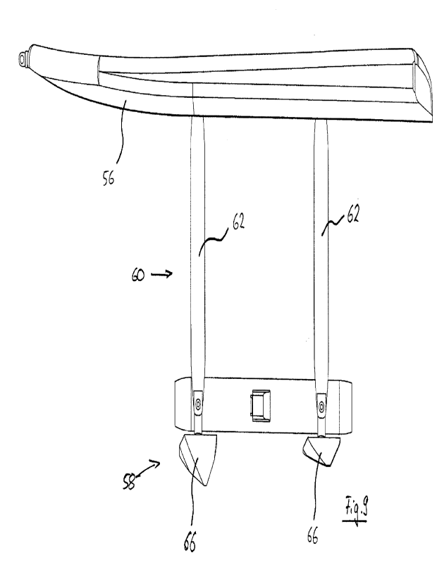
The water sports device 3 according to fig. 9 has an underwater drive 64. In
addition,
the water sports device 3 has a floating body 56 in the form of a floating
board and a
hydrofoil device 58 with two hydrofoils 66. The hydrofoil device 58 is
fastened to the
floating body 56 by means of a retaining device 60. The retaining device 60
comprises two links 62, by way of which the hydrofoil devices 58 are arranged
on the
floating body 56 so as to be able to move indirectly. The retaining device 60
allows
CA 03156773 2022-4-29
- 19 -
the hydrofoil device 58 to be transferred from a rest and/or starting position
close to
the floating body 56 into an operating position below the floating body 56. In
the
operating position and during a forward movement of the water sports device 3,
on
account of the buoyancy brought about by the hydrofoils 66 the floating body
56 can
be transferred into a position spaced apart from the water surface. The
underwater
motor module 2, which is shown only schematically in fig. 9, is formed as part
of the
hydrofoil device 58.
Figs. 10 to 12 schematically show an advantageous embodiment of an underwater
motor module 2 provided with an impeller 53, in which underwater motor module
blades 18 can be rotated about a blade axis A - preferably by at least +1- 100
- and
therefore can be adjusted in their angle of attack. In this respect, the
individual
blades 18 are connected to one another only indirectly. For this purpose, the
underwater motor module 2 has a motor 11 which is in the form of an internal
rotor
motor and has a stator 22 and a rotor 16. On its outer side directed away from
the
flow channel, the rotor 16 is mounted by way of two radial bearings 68, which
in the
present case are in the form of magnetic bearings, and an axial bearing 208,
which
in the present case is likewise in the form of a magnetic bearing. The multi-
part rotor
16 has an impeller ring 210 which has rotatable blade receptacles 211. A blade
18 is
arranged on each of the blade receptacles 211. The propulsion device 50 has an
adjusting ring 212 arranged coaxially along an axis of rotation R in relation
to the
rotor 16 or to the impeller ring 210. The adjusting ring 212 is likewise
hollow,
concomitantly forms the flow channel and is mounted on its outer side directed
away
from the flow channel. The spacing between the adjusting ring 212 and the
impeller
CA 03156773 2022-4-29
- 20 -
ring 210 in the axial direction (axis of rotation R) can be modified in this
respect. In
the present case, this is achieved by an actively electromagnetically actuable
adjusting means in a magnetic bearing 214 of the adjusting ring 212. The
adjusting
ring 212 engages with cylindrical outer portions of the blade receptacles 211
via
individual adjusting pins 216. When the axial spacing between the adjusting
ring 212
and the impeller ring 210 is modified via the magnetic bearing 214, the
interaction of
the adjusting pins 216 and the blade receptacles 211 converts this
translational
movement into a rotational movement of the blades 18, via which rotational
movement the blades 18 can be pivoted. As a result, the angle of attack of the
blades 18 can be set and likewise be defined.
CA 03156773 2022-4-29