Note: Descriptions are shown in the official language in which they were submitted.
CA 03156867 2022-04-04
WO 2021/071789 PCT/US2020/054313
-1-
COOLING PLATE SYSTEM, METHOD AND APPARATUS FOR
CLEAN FUEL ELECTRIC VEHICLES
CROSS-REFERENCE TO RELATED APPLICATION(S)
[0001] This application claims priority to, and the benefit of, co-pending
United States
Provisional Application No. 62/912,390, filed October 8, 2019, for all subject
matter
common to both applications. The disclosure of said provisional application is
hereby
incorporated by reference in its entirety.
FIELD OF THE INVENTION
[0002] The present invention is directed to an improved efficiency cooling
plate
apparatus, system, and method. It finds particular, although not exclusive,
application to
electric-powered aircraft and is suited for implementation in electric motors
for vertical
takeoff and landing (VTOL) multirotor aircraft configurations as well as fixed
wing and
other conventional propeller applications, including Advanced Air Mobility
(AAM) aircraft,
where the fuel-cell modules or other on-board sources of power transforms
hydrogen and
oxygen or other suitable energy-storage materials into electricity that is
then used to operate
one or more electric motors, depending upon the application and architecture..
The cooling
plate apparatus, system, and method include a cooling body comprising a
plurality of bores,
apertures and interior chambers working together to process fluid coolant and
function as a
heat sink and coolant circulation device, interconnecting with the body or
cooling system of
an electric motor and cooperatively functioning to transport heated fluid
coolant away from
electric motor components, dissipating heat generated by rotor-current or
stator-current
flowing through the electric motor to produce torque. The cooling plate
apparatus transfers
heat or thermal energy away from the electric motor using conduction,
convection and
CA 03156867 2022-04-04
WO 2021/071789 PCT/US2020/054313
-2-
radiation, while transporting fluid coolant to other components of a vehicle
for further
processing, then returning cooled fluid coolant into the cooling system of an
electric motor,
effectively partitioning heated fluid coolant, cooled fluid coolant, and
electrical circuitry in
a space saving design formed from a single part or minimal number of parts to
reduce
modes of failure and reduce required fasteners or connections to improve
robustness and
reliability while maintaining suitable aerodynamic characteristics to improve
motor function
and efficiency.
BACKGROUND
[0003] Although reduced scale multirotor aircraft (sometimes called multi-
copters) are
not new, they have been reduced scale models not intended for the rigors or
requirements of
carrying human passengers, and find use mostly either as toys, or for limited-
duration
surveillance or aerial photography missions with motion being controlled by
radio-control
remotes. As a result, these devices generally rely upon only unsophisticated
power
production systems that include electric motors, basic batteries, and heat
sinks, without
having any of the radiators, fluids (often referred to as coolant), cooling
fans, or monitoring
devices for cooling systems that passenger carrying powered vehicles commonly
provide.
For example, US Patent Application 20120083945 relates specifically to a
reduced scale
multi-copter, but does not address the safety, structural, or redundancy
features necessary
for FAA-certified passenger-carrying implementations, nor any of the systems
required to
implement a practical, passenger-carrying vehicle with fault-tolerance and
state-variable
analysis. The dynamics and integrity requirements of providing a full-scale
aircraft capable
of safely and reliably carrying human passengers and operating within US and
foreign
airspace are significantly different that those of previous reduced scale
models.
[0004] Generally, powered vehicles need to dissipate waste heat from
various systems
and subsystems those vehicles use, including heat from the friction of moving
parts and
waste heat generated by producing horsepower or shaft torque using rotor-
current or stator-
current. For example, in brushless DC motors, a rotor can include permanent
magnets that
generate a DC magnetic field (from the perspective of the rotor). That
magnetic field
interacts with currents flowing within the windings of the stator core (made
up of stacked
laminations) to produce a measurable torque between the rotor and stator,
resulting in
rotation. As the rotor rotates, magnitude and polarity of the stator currents
are continuously
CA 03156867 2022-04-04
WO 2021/071789
PCT/US2020/054313
-3-
varied such that torque remains near constant and conversion of electrical to
mechanical
energy is efficient, with current control performed by an inverter (e.g. 3-
phase modulating
inverter or similarly functioning digital controllers). This rotation of the
rotor and
conversion of energy at less than perfect efficiency create waste heat, and
heated parts
increase physical dimensions, leading to added friction in contacting and
rotating parts,
adding more heat. Heat also increases electrical resistance to the continued
flow of current
thus impacting efficiency, where greater resistance in the flow of current
also generates
additional heating of parts and components. Aircraft, automobiles, powered
boats and other
vehicles often use radiators to dissipate the waste heat of power generation.
[0005] Whether vehicles use motors, batteries, fuel cells, engines,
generators or other
means to propel, control, steer or monitor vehicle travel, these components
generate excess
heat that must be managed and dissipated from the system to prevent
overheating and
maintain efficient operating temperatures. Often, heat is transferred away
from components
that generate excess heat using a fluid. One way to do this is to use
airflows, either natural
or induced via cooling fans, which move air heated from the component into the
cooler
external atmosphere. Reduced scale devices generally rely upon only
unsophisticated heat
management systems that include basic passive heat sinks or motor frames and
housings
with cast or molded fins that increase surface area to dissipate heat the same
way that
computers and other common electronic devices do, without having even the
radiators,
fluids (often referred to as coolant), cooling fans, or monitoring devices for
cooling systems
that passenger carrying powered vehicles commonly provide. Another common
method is
to use a liquid flow that moves through components, heating as it travels in a
circuit to a
cooler region, thereby lowering component temperatures as it circulates
through heat
generating systems. Using both radiation of heat into the external environment
and a
reservoir of cold fluid improves the overall efficiency of the system and the
ability to adjust
to a range of different dynamic conditions, but it requires a more
sophisticated system to
implement thermodynamic principles to achieve the required parameters.
[0006] A heat sink transfers thermal energy from a higher temperature
device to a
lower temperature fluid medium. The fluid medium may be air, water,
refrigerants or oil. In
thermodynamics a heat sink is defined as a heat or thermal energy reservoir
that can absorb
a large amount of heat or thermal energy without significantly changing
temperature. For
example, the atmosphere or an ocean may serve as a heat sink. A heat source is
a heat
CA 03156867 2022-04-04
WO 2021/071789 PCT/US2020/054313
-4-
reservoir or thermal energy reservoir that can supply large amounts of energy
without
undergoing a significant change in temperature. Practical heat sinks for
electronic devices
must have a temperature higher than the surroundings to transfer heat by
convection,
radiation, and conduction. The power supplies of electronics are not perfectly
efficient, and
are subject to electrical resistance, so extra heat is produced that may be
detrimental to the
function of the device. As such, a heat sink is often included in the design
to disperse heat.
[0007] The principle of a heat sink operates according to Fourier's law of
heat
conduction: when there is a temperature gradient in a body, heat will be
transferred from the
higher temperature region to the lower temperature region. The rate at which
heat is
transferred by conduction is proportional to the product of the temperature
gradient and the
cross-sectional area through which heat is transferred. Newton's law of
cooling states, the
rate of heat loss (cooling) of an object (whether by conduction, convection,
or radiation) is
approximately proportional to the temperature difference AT between the body
and its
surroundings. Heat sinks transfer heat or thermal energy from electronic
devices producing
excess heat to the periphery of the heat sink when in contact with a cooler
surrounding
environment, and then lose that excess heat to the surrounding environment,
thereby cooling
the electronic devices.
[0008] Conversely, heat pumps move thermal energy in the opposite direction
of
spontaneous heat transfer, by absorbing heat from a cold space and releasing
it to a warmer
one. A heat pump uses a small amount of external power to accomplish the work
of
transferring energy from the heat source to the heat sink. A heat sink is a
passive heat
exchanger that transfers the heat generated by an electronic or a mechanical
device to a fluid
medium, often air or a liquid coolant, where it is dissipated away from the
device, thereby
allowing regulation of the device's temperature at optimal levels. A heat pump
is a machine
or device that moves heat from a source location at a lower temperature to a
heat sink
location at a higher temperature using mechanical work or a high-temperature
heat source.
A heat pump may function as a "heater" if the objective is to warm the heat
sink, or a
"refrigerator" if the objective is to cool the heat source. In either case,
the operating
principles are identical. Heat is transferred from a relatively cooler place
to a relatively
warmer place. One way to interconnect objects in need of cooling with objects
in need of
heating when those objects cannot be physically joined is by using a heat
exchanger and
working fluids. A fluid heat recovery apparatus, commonly known as a heat
exchanger, is a
CA 03156867 2022-04-04
WO 2021/071789 PCT/US2020/054313
-5-
device that transfers heat between one or more mediums. Liquid heat transfer
is the most
common medium used in heat exchangers, with gas mediums also used within
different
applications. Fluids (liquids, gases and air) can be separated by an enclosed
area or in direct
contact in the heat exchanger. Fluids in this application are defined in
accordance with
conventional meanings as substances such as liquids or gases that are capable
of flowing
and can change shape when acted upon by a force. The flow of fluids can be
directed from
different sources to different destinations, allowing heat exchangers to
perform heat transfer
for a variety of objects remote from each other.
[0009] The dynamics and integrity requirements of providing a full scale
electric
aircraft capable of safely and reliably carrying human passengers are
significantly different
that those of reduced scale models. Such a vehicle requires state-of-the-art
electric motors,
electronics and computer technology with high reliability, safety, simplicity,
and redundant
control features, coupled with advanced avionics and flight control
techniques. Generating
and distributing electrical power aboard a vehicle (e.g. from one or more fuel
cells to one or
more motors or motor controllers) presents several challenges including
inefficient
performance, waste heat generation and dissipation rates, system complexity
related to
maintenance, errors and failures, and constraints related to space, weight,
aerodynamics,
and safety, requiring a more efficient method to implement the relevant
electromagnetic,
chemical reaction, and thermodynamic principles in a variety of settings and
conditions to
achieve viable flight performance.
SUMMARY
[0010] There is a need for an improved lightweight, highly efficient, fault-
tolerant
cooling plate system, method, and apparatus to augment motor cooling,
especially in
conjunction with power generation subsystems for a full-scale, clean fuel,
electric-powered
VTOL aircraft that leverages advantageous characteristics in its design to
improve
efficiency and effectiveness in managing and distributing heat or thermal
energy produced
from the generation of electrical power (voltage and current) to dynamically
meet needs of
an aircraft without compromising other functionalities, and to maintain one or
more motors
at preferred operating conditions (e.g. temperatures) for proper vehicle
performance.
Further, there is a need to simultaneously dissipate waste heat from power
generating
systems and prevent power and electrical systems from overheating, while
limiting the
CA 03156867 2022-04-04
WO 2021/071789
PCT/US2020/054313
-6-
number, mass, and size of systems used within an aircraft due to restrictions
on the volume
and mass of the vehicle required by flight parameters that must be adhered to
in order to
successfully maintain aircraft flight. The present invention is directed
toward further
solutions to address these needs, in addition to having other desirable
characteristics.
Specifically, the present invention relates to a method and apparatus for
managing thermal
energy produced by the generation and distribution of electrical power using
fuel cell
modules in a full-scale vertical takeoff and landing manned or unmanned
aircraft having a
multirotor airframe fuselage containing a system to generate electricity from
fuels such as
hydrogen as part of the design of a full-scale, clean-fueled, electric
vehicle, particularly a
full-scale multirotor aircraft, also referred to herein as a multirotor
aircraft, a Personal Air
Vehicle (PAV) or an Air Mobility Vehicle (AMV) such as the invention described
in U.S.
Patent No. 9,764,822, as well as U.S. Patent No. 9,242,728, each incorporated
by reference
herein.
[0011] In
accordance with example embodiments of the present invention, a cooling
plate apparatus includes a cooling body comprising a top wall offset in an
axial direction
from a base wall; a hub wall interposed between the top wall and the base
wall; and a
perimeter wall offset from the hub wall at a greater offset distance from a
central axis than
the hub wall. The perimeter wall is interposed between the top wall and the
base wall,
connecting a perimeter of the top wall to a perimeter of the base wall. The
top wall, the base
wall, the hub wall, the perimeter wall and the cooling body each include a
heat conducting
material. The cooling plate includes an interior fluid cavity configured to
hold and circulate
fluid coolant (e.g. liquids or gases). The interior fluid cavity is defined by
and disposed
within an interior surface of the hub wall, an interior surface of the top
wall, an interior
surface of the base wall, and an interior surface of the perimeter wall. At
least one partition
wall is interposed between the top wall and the base wall. The partition wall
is configured to
separate portions of the interior fluid cavity and enable a directional flow
through the
interior fluid cavity. An aperture wall isolates the interior fluid cavity
from a pass-through
conduit for electrical wires that pass through and connect to the electric
motor. A plurality
of fasteners configured to fit a subset of a plurality of bores in the cooling
body. The
plurality of bores further defines one or more fluid inlets receiving fluid
coolant into a first
portion of the interior fluid cavity, one or more fluid outlets dispensing
fluid coolant from a
second portion of the interior fluid cavity.
CA 03156867 2022-04-04
WO 2021/071789 PCT/US2020/054313
-7-
[0012] In accordance with aspects of the present invention, the cooling
plate apparatus
can include a central aperture extending through the cooling plate apparatus,
through the top
wall and through the base wall, aligning with a central axis of an electric
motor and/or
driveshaft or propeller shaft thereof, surrounded and defined by an exterior
surface of the
hub wall; and one or more fluid conduit bores isolating fluid coolant flowing
into the
electric motor from the interior fluid cavity. The cooling plate apparatus can
removably
connect to the electric motor by attaching a top surface of the cooling plate
to a housing or
bottom of a stator of the electric motor, making heat conductive contact using
a first set of
the plurality of fasteners to create a heat conducting junction between the
electric motor and
the cooling plate apparatus. The first set of fasteners of the plurality of
fasteners can each
comprise a bolt, extending through both the top wall and the base wall of the
cooling body
using a bore of a first subset of the plurality of bores and threaded to mate
with a motor bore
disposed within a housing or bottom of a stator of the electric motor, wherein
a first set of
bores of the plurality of bores are concentric with and of a same diameter as
a plurality of
motor bores in the electric motor. The first set of fasteners or a second set
of fasteners of the
plurality of fasteners can extend through, and attach the cooling plate
apparatus to, one or
more of a support bracket, an elongate support arm, a support armature or an
airframe
fuselage. The second set of fasteners can each comprise a bolt, extending
through the base
wall of the cooling body but not the top wall and can be threaded to mate with
a second
subset of the plurality of bores comprising blind bores having threads and
terminating inside
one or more of the hub walls or the cooling body. The plurality of fasteners
can each
comprise a heat conducting material.
[0013] In accordance with aspects of the present invention, the cooling
plate can
include an aperture wall having an exterior surface that surrounds and defines
a pass
through aperture dimensioned, and disposed to enable electrical wires to pass
through the
cooling plate apparatus, wherein the aperture wall isolates the interior fluid
cavity from the
pass through aperture, with an interior surface of the aperture wall further
defining the
interior fluid cavity, and wherein the electrical wires comprise power
transmission wires or
signal transmission wires to connect the electric motor or motor sensors to
one or more of
an electricity generating source subsystem or a diagnostic subsystem.
[0014] In accordance with aspects of the present invention, the interior
surface of the
hub wall can be contiguous with an interior surface of the partition wall. The
interior
CA 03156867 2022-04-04
WO 2021/071789 PCT/US2020/054313
-8-
surface of the hub wall can be contiguous with an interior surface of the
aperture wall as
well.
[0015] In accordance with aspects of the present invention, the top wall of
the cooling
plate apparatus can be parallel to the base wall. The hub wall and perimeter
wall can be
annular in cross-section, and the top wall and the base wall can each have a
circular
perimeter, and the hub wall can be concentric with the perimeter wall. The hub
wall and the
perimeter wall can each have a wall thickness less than a maximum/outer radius
of the
cooling plate apparatus while the hub wall is concentric with the perimeter
wall. The hub
wall, the perimeter wall, the partition wall and an aperture wall can each
have an axial
height of an axial distance of the offset between the top wall and the base
wall and each join
a top surface of the base plate at a perpendicular angle, and each join a
bottom surface of the
top plate at a perpendicular angle. The interior surface of the hub wall is
contiguous with an
interior surface of the perimeter wall, partition wall, and aperture wall.
[0016] In accordance with aspects of the present invention, the cooling
plate apparatus
can include a fluid inlet to receive fluid coolant into the interior fluid
cavity, the interior
fluid cavity shaped to transport the fluid coolant around a central axis of
the cooling plate
apparatus and dispense fluid coolant out of a fluid outlet, wherein the fluid
coolant flowing
in from the fluid inlet is prevented from mixing with the fluid flowing out of
the fluid outlet
by the partition wall. Cooling capacity can be modulated by increasing or
decreasing the
coolant flow. Cooling capacity also can be modulated by selecting a particular
fluid coolant
or coolant medium (e.g. using water rather than oil or other fluid coolants).
[0017] In accordance with aspects of the present invention, the cooling
plate can be a
heat sink for the electric motor, transferring heat generated by the electric
motor by
convection, radiation, and/or conduction from the electric motor through the
cooling body
and then into fluid coolant circulating inside the interior fluid cavity or
out into an external
environment surrounding the cooling plate apparatus. The heat conducting
material of the
cooling plate apparatus can include a heat conducting alloy. The heat
conducting alloy can
be one of titanium, aluminum, or combinations thereof.
[0018] In accordance with aspects of the present invention, a first part of
the cooling
body including the top wall can be machined from a first piece of heat
conducting alloy and
CA 03156867 2022-04-04
WO 2021/071789 PCT/US2020/054313
-9-
disposed to fit in a fluid-tight configuration with a second part of the
cooling body
comprising the base wall that can be machined from a second piece of heat
conducting
alloy, wherein first part is then fastened to the second part of the cooling
body. The base
wall of the cooling body and/or the top wall of the cooling body further can
comprise one or
more coupling structures to mate the base wall to the top wall. The first part
can be fastened
to the second part of the cooling body using a third set of the plurality of
fasteners, each
comprising a bolt, extending through the base wall of the cooling body but not
the top wall
and threaded to mate with a third subset of the plurality of bores comprising
blind bores
having threads and terminating inside one or more of the perimeter wall, the
hub wall or the
cooling body. The cooling body can include the first part and the second part
both
constructed of the heat conducting alloy comprising aluminum with the first
part coupled to
the second part, the second part comprising a recessed cavity creating the
fluid cavity,
wherein a gasket creating a fluid seal is interposed between the first part
and the second part
when the first part is coupled to the second part. In an alternative example
embodiment, the
cooling plate apparatus can be formed as a single part from the heat
conducting alloy using
a three-dimensional (3D) printing tool or technique. The entire cooling body
can be 3D
printed as a solid body from aluminum, titanium or other 3D-printing materials
known in
the art, having a singular solid outer form and a hollow interior, while
otherwise comprising
the key elements, components and features described herein.
[0019] In accordance with aspects of the present invention, the first
subset of the
plurality of bores can be disposed within or through the hub wall at equal
radial distances
from a central axis of the cooling plate apparatus with a uniform spacing
comprising equal
distances between a center axis of each bore of the first subset to a center
axis of an adjacent
bore of the first subset of the plurality of bores. A fourth subset of the
plurality of bores of
the cooling plate can include conduit bores configured to connect fluid
conduits or electrical
wires and connections thereof to the electric motor, depending on the
interface design of the
particular electric motor.
[0020] In accordance with aspects of the present invention, the interior
fluid cavity can
contain and circulate a fluid coolant that can be a liquid coolant or a phase-
change fluid.
The interior fluid cavity can contain and circulate a liquid coolant including
water, or an
antifreeze (e.g. combination, mixture or solution of water and ethylene
glycol), or oil. The
cooling plate apparatus can be in fluid communication with one or more of
coolant pumps,
CA 03156867 2022-04-04
WO 2021/071789 PCT/US2020/054313
-10-
coolant reservoirs, coolant junctions, coolant outlets or coolant inlets by
using one or more
high-pressure lines or fluid conduits that are removably connected to and in
fluid
communication with the cooling plate via fluid inlet fittings or fluid outlet
fittings. The
cooling plate apparatus can be in fluid communication with a cooling system or
fluid
circulation system of the electric motor, wherein heated fluid coolant from
the electric
motor is circulated through the cooling plate apparatus using the interior
fluid cavity to cool
the heated fluid coolant by thermal energy transfer using convection,
radiation, and/or
conduction, wherein cooled fluid coolant is thereafter recirculated into the
cooling system
or fluid circulation system of the electric motor. The cooling plate apparatus
can include
one or more fluid inlets that receive fluid coolant from one or more high-
pressure lines or
fluid conduits through a fluid inlet fitting joining the one or more high-
pressure lines or
fluid conduits to a fifth subset of the plurality of bores, thereby forming a
fluid tight conduit
through the base wall into a first portion of the interior fluid cavity. The
cooling plate
apparatus can include one or more fluid outlets that dispense fluid coolant to
one or more
high-pressure lines or fluid conduits through a fluid outlet fitting joining
the one or more
high-pressure lines or fluid conduits to a sixth subset of the plurality of
bores, thereby
forming a fluid tight conduit through the base wall into a second portion of
the interior fluid
cavity. The cooling plate apparatus can generate a flow of fluid coolant
through
interconnected components in fluid communication comprising: a coolant source,
including
one or more of coolant pumps, coolant reservoirs, coolant junctions, or
coolant outlets; an
inlet line comprising a high-pressure line or fluid conduit disposed through a
fluid conduit
bore of a fourth subset of the plurality of bores that is removably connected
to, and in fluid
communication with, at a first end, a coolant source, including one or more of
coolant
pumps, coolant reservoirs, coolant junctions, or coolant outlets, and at a
second end, an inlet
of a cooling system or fluid circulation system of the electric motor using a
throughlet
fitting; the cooling system or fluid circulation system of the electric motor;
the cooling
system or fluid circulation system of the electric motor into the cooling
plate apparatus, a
first intermediate line comprising a high-pressure line or fluid conduit
disposed through a
fluid conduit bore of a fourth subset of the plurality of bores that is
removably connected to,
and in fluid communication with, at a first end, an outlet of the cooling
system or fluid
circulation system of the electric motor using a throughlet fitting, and at a
second end, an
inlet fitting of the one or more fluid inlets of the cooling body; the
interior fluid cavity of
the cooling body of the cooling plate apparatus via one or more fluid inlets
configured to
receive fluid coolant; a central axis of the cooling plate apparatus,
circulating within the
CA 03156867 2022-04-04
WO 2021/071789
PCT/US2020/054313
-11-
interior fluid cavity in a direction from the fluid inlet to the fluid outlet,
maintaining fluid
contact with one or more of an interior surface of the hub wall, an interior
surface of the top
wall, an interior surface of the base wall, an interior surface of the
perimeter wall, an
interior surface of the partition wall, an interior surface of an aperture
wall, or combinations
thereof; the interior fluid cavity of the cooling body of the cooling plate
apparatus via a
fluid outlet removably connected to, and in fluid communication with, a first
end of an
outlet line comprising a high-pressure line or fluid conduit via a fluid
outlet fitting, wherein
a second end of the outlet line is removably connected to, and in fluid
communication with,
the coolant source; and thereby directing a flow of coolant from a coolant
source, through
the inlet line, through the cooling system or fluid circulation system of the
electric motor;
from the cooling system or fluid circulation system of the electric motor into
the cooling
plate apparatus, through the first intermediate line, into the interior fluid
cavity of the
cooling body of the cooling plate apparatus via the one or more fluid inlets,
around the
central axis of the cooling plate apparatus, in a direction from the fluid
inlet to the fluid
outlet, out of the interior fluid cavity via the fluid outlet through an
outlet line via a fluid
outlet fitting, back to the coolant source, cooling the electric motor and
parts thereof by
conduction, convection, radiation, and thereby transporting unheated fluid
coolant to, and
heated coolant from, the electric motor in an iterative cycle.
[0021] In accordance with aspects of the present invention, the cooling
plate apparatus
can include a plurality of fluid inlets, a plurality of inlet lines, a
plurality of intermediate
lines, a plurality of fluid outlets, and a plurality of outlet lines, the
plurality of fluid inlets
and the plurality of fluid outlets each disposed within the cooling body
enabling fluid to
pass into and out of the interior fluid cavity. The cooling plate apparatus
can be further
configured to generate a flow of fluid coolant through each of the plurality
of inlets and the
plurality of outlets.
[0022] In accordance with aspects of the present invention, the cooling
plate
apparatus can be indirectly coupled to, and not directly in fluid
communication with, a
cooling system of the electric motor. The cooling body can be interconnected
with heat
conducting components of the electric motor, thereby transferring heat from
the electric
motor to the cooling body by surface contact and conduction using the top
wall, the bores
and the fasteners. The cooled fluid coolant can be then recirculated and the
cooling plate
apparatus can generate a flow of fluid coolant through interconnected
components in fluid
CA 03156867 2022-04-04
WO 2021/071789 PCT/US2020/054313
-12-
communication comprising: a coolant source, comprising one or more of coolant
pumps,
coolant reservoirs, coolant junctions, or coolant outlets; an inlet line
comprising a high-
pressure line or fluid conduit that is removably connected to, and in fluid
communication
with, at a first end, a coolant source, comprising one or more of coolant
pumps, coolant
reservoirs, coolant junctions, or coolant outlets, and at a second end, an
inlet fitting of the
one or more fluid inlets of the cooling body configured to receive fluid
coolant into the
interior fluid cavity of the cooling body; a central axis of the cooling plate
apparatus,
circulating within the interior fluid cavity in a direction from the fluid
inlet to the fluid
outlet, maintaining fluid contact with one or more of an interior surface of
the hub wall, an
interior surface of the top wall, an interior surface of the base wall, an
interior surface of the
perimeter wall, an interior surface of the partition wall, an interior surface
of an aperture
wall, or combinations thereof; the interior fluid cavity of the cooling body
of the cooling
plate apparatus via a fluid outlet removably connected to, and in fluid
communication with,
a first end of an outlet line comprising a high-pressure line or fluid conduit
via a fluid outlet
fitting, wherein a second end of the outlet line is removably connected to,
and in fluid
communication with, the coolant source. The cooling plate apparatus can
thereby direct a
flow of coolant from a coolant source, through the inlet line, into the
cooling plate
apparatus, into the interior fluid cavity of the cooling body of the cooling
plate apparatus via
the one or more fluid inlets, around the central axis of the cooling plate
apparatus, in a
direction from the fluid inlet to the fluid outlet, out of the interior fluid
cavity via the fluid
outlet through an outlet line via a fluid outlet fitting, back to the coolant
source, cooling the
electric motor and parts thereof by conduction, convection, radiation, and
thereby
transporting heat from the electric motor in an iterative cycle.
[0023] In accordance with aspects of the present invention, the cooling
plate apparatus
can further comprise a seventh subset of bores disposed into or through the
perimeter wall,
defining one or more of fluid inlets, fluid outlets, fluid conduit bores, or
sensor ports. The
electrical wires that pass through and connect to the electric motor can
comprise one or
more of power supply wires, three phase power connectors, temperature sensors,
hall
sensors, speed and position sensors, resolvers, tandem resolvers, encoders,
sensors for
synchronizing electrical and mechanical motor angle, or sensors for
controlling position,
direction and rotation speed of the electric motor. Additional wires of the
electrical wires
can pass through a central aperture extending through the cooling plate
apparatus or the
pass-through conduit for electrical wires.
CA 03156867 2022-04-04
WO 2021/071789 PCT/US2020/054313
-13-
BRIEF DESCRIPTION OF THE DRAWINGS
[0024] These and other characteristics of the present invention will be
more fully
understood by reference to the following detailed description in conjunction
with the
attached drawings, in which:
[0025] FIG. 1 depicts a cooling plate apparatus and related components;
[0026] FIG. 2 depicts a cooling plate apparatus and systems connectivity
for various
related components of the invention;
[0027] FIG. 3 depicts side views of the electric motor and cooling plate
apparatus;
[0028] FIG. 4 depicts a top view of the cooling plate apparatus;
[0029] FIG. 5 depicts a top view of the cooling plate apparatus;
[0030] FIG. 6 depicts front, cutaway and rear views of the electric motor
and cooling
plate components;
[0031] FIG. 7 depicts front, cutaway and rear views of the electric motor
and cooling
plate components;
[0032] FIG. 8 depicts multiple electric motor sizes and front, cutaway and
rear views
of the electric motor and cooling plate components;
[0033] FIG. 9 depicts various views of the electric motor and cooling plate
fittings and
electrical connections;
[0034] FIG. 10 depicts various views of the electric motor and cooling
plate fittings
and electrical connections;
[0035] FIG. 11 depicts various side cutaway views of the electric motor and
cooling
plate fittings and electrical connections;
[0036] FIG. 12 depicts various side cutaway views of the electric motor and
cooling
plate fittings and cooling vectors;
[0037] FIG. 13 depicts the cooling plate fittings in detail;
[0038] FIG. 14 depicts the electrical wiring components within the cooling
plate
apparatus;
[0039] FIG. 15 depicts example detailed views of electrical connection and
fluid
conduit components;
[0040] FIG. 16 depicts example detailed views of electrical wiring and
fluid conduit
components;
CA 03156867 2022-04-04
WO 2021/071789 PCT/US2020/054313
-14-
[0041] FIGS. 17A, 17B, 17C, 17D depict a system block diagram for
practicing the
present invention, including logic controlling the integrated system for
multimode thermal
energy transfer and related components;
[0042] FIG. 18 depicts an example system diagram of electrical and systems
connectivity for various control interface components of a system of the
invention;
[0043] FIG. 19 depicts example configurations of fuel cells within the
multirotor
aircraft and example subcomponents of fuel cells in at least one fuel cell
module within the
multirotor aircraft;
[0044] FIG. 20 depicts an example of control panels, gauges and sensor
output for the
multirotor aircraft;
[0045] FIG. 21 depicts profile diagrams of the multirotor aircraft
demonstrating
example positions of fuel supply system components and power generation
subsystems and
cooling plates within the multirotor aircraft;
[0046] FIG. 22 depicts example diagrams of the configuration of power
generation
subsystem heat transfer and exchange source components within the multirotor
aircraft that
depicts two views demonstrating the position and compartments housing the fuel
supply and
power generation subsystems depicting fluid coolant conduits;
[0047] FIG. 23 depicts side and top views of a multirotor aircraft with six
rotors
cantilevered from the frame of the multirotor aircraft in accordance with an
embodiment of
the present invention, indicating the location and compartments housing the
fuel supply and
power generation subsystems; electrical and systems connectivity of various
fuel supply,
power generation, and motor control components of a system of the invention;
[0048] FIG. 24 depicts an example diagram of the fuel tank, fuel cell,
radiator, heat
exchanger and air conditioning components and interrelated conduits for heat
transfer
among components; and
[0049] FIG. 25 depicts a flow chart that illustrates the present invention
in accordance
with one example embodiment.
DETAILED DESCRIPTION
[0050] To provide an overall understanding, certain illustrative
embodiments will now
be described; however, it will be understood by one of skill in the art that
the systems and
methods described herein can be adapted and modified to provide systems and
methods for
other suitable applications and that other additions and modifications can be
made without
CA 03156867 2022-04-04
WO 2021/071789 PCT/US2020/054313
-15-
departing from the scope of the systems and methods described herein. In
particular, the
systems and methods described herein can be adapted to apply to inrunner as
well as
outrunner style electric motors, provided an effective thermal path can be
accomplished into
the interior heat-generating area of the electric motor, whether in the rotor
or the stator
depending on the mechanics of the design of a particular electric motor.
[0051] Unless otherwise specified, the illustrated embodiments can be
understood as
providing exemplary features of varying detail of certain embodiments, and
therefore,
unless otherwise specified, features, components, modules, and/or aspects of
the
illustrations can be otherwise combined, separated, interchanged, and/or
rearranged without
departing from the disclosed systems or methods.
[0052] An illustrative embodiment of the present invention relates to an
improved
efficiency cooling plate apparatus for cooling motors or other heat generating
components,
having a cooling body including a plurality of bores, apertures and interior
chambers
working together to process and circulate fluid coolant and function as a heat
sink device.
The invention is capable of interconnecting with the cooling system of an
electric motor and
cooperatively functioning to transfer thermal energy away from the electric
motor using
principles of thermodynamics including conduction, convection and radiation,
while
transporting heated fluid coolant away from heated motor components and to
other
components of a vehicle for further processing, then returning cooled fluid
coolant into the
cooling system of an electric motor. The design of the cooling plate apparatus
components
effectively partitions heated fluid coolant, cooled fluid coolant, and
electrical circuitry in
isolated dedicated sections of the apparatus that prevent infiltration of
other fluids while
increasing surface contact with components used to establish a favorable rate
and vector of
heat transfer in a space saving design formed from a single part or minimal
number of parts
to reduce modes of failure and reduce required fasteners or connections to
improve
robustness and reliability while maintaining suitable aerodynamic
characteristics. The
cooling plate apparatus may be formed as a single part from a heat conducting
alloy using a
three-dimensional printing tools or techniques, including by additive
manufacture based on
a from a computer-aided design (CAD) with electron beam or selective laser
melting, direct
metal laser sintering (DMLS), powder bed fusion, gas metal arc welding 3D
printing, or
other processes known in the art.
CA 03156867 2022-04-04
WO 2021/071789
PCT/US2020/054313
-16-
[0053] The
cooling plate apparatus, method and system can be integrated into a full-
scale clean fuel electric-powered multirotor aircraft as in the vehicles
described in U.S.
Patent No. 9,764,822 and U.S. Patent No. 9,242,728, incorporated by reference
herein. The
one or more fuel cell modules of the integrated system comprise a plurality of
fuel cells
individually functioning in parallel or series but working together to process
gaseous
oxygen and gaseous hydrogen extracted from liquid hydrogen by heat exchangers,
using an
electrical circuit configured to collect electrons from the plurality of
hydrogen fuel cells to
supply voltage and current to motor controllers commanded by autopilot control
units
configured to select and control an amount and distribution of electrical
voltage and torque
or current for each of the plurality of motor and propeller assemblies. Lift
and propulsion
are provided by pairs of small AC or DC brushless electric motors each driving
directly-
connected pairs of counter-rotating propellers, also referred to as rotors.
The use of counter-
rotating propellers on each pair of motors cancels out the torque that would
otherwise be
generated by the rotational inertia. Fuel cell modules, motors, motor
controllers, batteries,
circuit boards, and other electronics must have excess or waste heat removed
or dissipated.
The integrated system comprises at least a power generation subsystem
comprising one or
more radiators in fluid communication with the one or more fuel cell modules,
configured
to store and transport a coolant, and a thermal energy control subsystem
comprising a heat
exchanger configured with a plurality of fluid conduits. The integrated system
can also
include a fuel supply subsystem comprising a fuel tank in fluid communication
with one or
more fuel cell modules and configured to store and transport a fuel such as
liquid hydrogen,
gaseous hydrogen, or a similar fluid. When power is provided by one or more
fuel cell
modules for generating electrical voltage and current, electronics monitor and
control
electrical generation and excess heat or thermal energy production, and motor
controllers
then control the commanded voltage and current to each motor and to measure
its
performance, using control system including automatic computer monitoring by
programmed single or redundant digital autopilot control units (autopilot
computers), or
motor management computers, controls each motor-controller and motor to
produce pitch,
bank, yaw and elevation, while also simultaneously controlling cooling and
heating
parameters and thermodynamic operating conditions, valves and pumps while
measuring,
calculating, and adjusting temperature and heat transfer of aircraft
components, to protect
motors, fuel cells, and other critical components from exceeding operating
parameters. One
or more temperature sensing devices or thermal energy sensing devices are
configured to
measure thermodynamic operating conditions with the autopilot control unit
comprising a
CA 03156867 2022-04-04
WO 2021/071789 PCT/US2020/054313
-17-
computer processor configured to compute a temperature adjustment protocol
comprising
one or more priorities for energy transfer using one or more thermal
references and select
and control, based on the temperature adjustment protocol, an amount and
distribution of
thermal energy transfer from one or more sources to one or more thermal energy
destinations.
[0054] FIGS. 1-25, wherein like parts are designated by like reference
numerals
throughout, illustrate an example embodiment or embodiments of a lightweight,
high
efficiency, fault-tolerant cooling plate apparatus, method and system,
according to the
present invention. Although the present invention will be described with
reference to the
example embodiment or embodiments illustrated in the figures, it should be
understood that
many alternative forms can embody the present invention. One of skill in the
art will
additionally appreciate different ways to alter the parameters of the
embodiment(s)
disclosed, such as the size, shape, or type of elements or materials, in a
manner still in
keeping with the spirit and scope of the present invention.
[0055] FIG. 1 and FIG. 2 depict an example embodiment of a cooling plate
apparatus
100 and systems connectivity for various related components of the invention.
The cooling
plate apparatus 100 incorporates a cooling body 102 of an aerodynamic
configuration and
structure that is constructed from suitably strong heat conducting material
such that the
cooling plate apparatus 100 can function as a heat sink and structural support
for one or
more electric motors 126 without comprising the positioning or aerodynamics of
the
mounted electric motor 126. The cooling body 102 is constructed to be capable
of being
disposed in a position intervening between one or more mounting brackets and
one or more
electric motors 126, requiring only replacement standard motor fasteners with
longer, heat
conducting fasteners 122 of the same diameter and configuration (including
e.g. thread type,
lead, angle, pitch, starts, depth, major diameter, minor diameter or taper for
threaded
fasteners), allowing the same aligning method to be continued to mate the
motor 126,
cooling plate apparatus 100 and support bracket as was used for the motor and
support
bracket alone. The cooling plate apparatus 100 is shaped to meet a number of
different
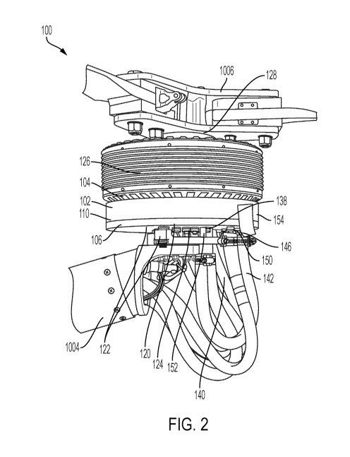
motor types and diameters, having a plurality of bores 120 that align with one
or more
motor bores 134 present in the motor 126 from standard original manufacture.
The cooling
body 102 can be connected to the body of the motor 126 by securing fasteners
122 through
a mounting bracket connected to e.g. an elongate support arm 1004 (belonging
to e.g. a
CA 03156867 2022-04-04
WO 2021/071789 PCT/US2020/054313
-18-
vehicle such as an aircraft 1000), then into or through one or more of the
plurality of bores
120, and optionally then into or through the one or more motors 126 by
threading into or
otherwise connecting to one or more motor bores 134. The motor 126 may then be
connected to or coupled with one or more propellers or rotors 1006 such that
attachment of
the cooling body 102 (e.g. to the stator 130, frame or body of the motor 126)
does not
interfere with the function of the motor 126 to rotate the rotor 132, motor
shaft 128 and one
or more propellers or rotors 1006. In an example embodiment, the cooling body
102
comprises a top wall 104, base wall 106 and perimeter wall 110, the interior
surfaces of
each defining an interior fluid cavity 116 constructed to circulate fluid
coolant 118 that may
be used to perform heat transfer to dissipate or remove excess or waste heat
or thermal
energy generated by a motor 126, either indirectly on a motor 126 through
surfaces and
components including the cooling body 102, or by directly coupling with the
motor 126 to
come into fluid communication with the internal cooling system of the motor
126 itself. If
indirectly coupled to a cooling system of the motor 126, the cooling plate
apparatus 100
interconnects the cooling body 102 and heat conducting components of the motor
126
including the base, stator 130, frame, or body of the motor 126, thereby
transferring heat
from the motor 126 to the cooling body 102 by surface contact and contact
between bores
(120, 134) and fasteners 122. If directly coupled to a cooling system of the
electric motor
126, the cooling plate apparatus 100 interconnects with the flow of fluid
coolant 118 into
and out of the motor 126, in seamless fluid communication with the motor 126
and the
cooling source 1010 or heat transfer or management system 1010 used with that
motor 126
(e.g. a radiator, heat sink, or heat exchanger). The cooling body 102 and
motor 126 may be
interconnected in fluid communication using a number of fluid conduits 142 or
high
pressure lines that deliver or remove fluid coolant 118, that can be attached
to the cooling
body 102 using one or more fluid inlet fittings 146, one or more fluid outlet
fittings 150, or
one or more throughlet fittings 152 that fit fluid conduits 142 or high
pressure lines,
securely connecting thereto by any number of methods known in the art (e.g. by
clamps,
locks, friction, adhesive, etc.). Throughlet fittings152 are designed,
constructed, and
disposed to bypass fluid coolant 118 into the motor 126 without exposing that
fluid to the
interior of the cooling body 102, while still preserving contact with the
cooling body 102 for
thermodynamic transfer purposes. In an example embodiment, the cooling plate
apparatus
100 comprises a central aperture 124 extending through the cooling plate
apparatus 100 that
aligns with the central aperture 124 of the electric motor 126 where the motor
shaft 128 or
electrical wires 140 may be passed through or accessed. Importantly, the
cooling body 102
CA 03156867 2022-04-04
WO 2021/071789
PCT/US2020/054313
-19-
can be specifically constructed to secure or guide electrical wires 140
through the perimeter
of the cooling body 102 without allowing those wires 140 to come in contact
with the
interior of the cooling body 102 or fluid coolant 118, using the central
aperture 124, one of
the plurality of bores 120, or a pass-through conduit defined by an aperture
wall 114 of the
cooling body 102 isolating the interior fluid cavity 116 from electrical wires
140 that pass
through and connect to the electric motor 126. The walls and components of the
cooling
plate apparatus 100 can be securely attached or mated using a plurality of
fasteners 122
configured to fit a subset of a plurality of bores 120 in the cooling body
102.
Interconnection of components as described herein provides cooling of an
electric motor
126 regardless of whether or not that electric motor 126 has any internal
fluid cooling ports
to provide fluid communication, or is cooled by other means. In an alternative
example
embodiment, the cooling plate apparatus can be formed as the first part and
the second part
both from the heat conducting alloy using a three-dimensional (3D) printing
tool, wherein
the base wall of the cooling body and/or the top wall of the cooling body
further comprise
one or more coupling structures to mate the base wall to the top wall. The one
or more
coupling structures can be formed during the three-dimensional (3D) printing
of the first
part and the second part or attached thereafter, and the one or more coupling
structures can
comprise one or more common coupling devices and components including posts,
slots,
ribs, pegs, hooks, fins, lips, contours, finger projections, tabs, press fits,
snap fits, threads,
protrusions, shaped recesses, combinations thereof, or similar coupling
structures known in
the art. In alternative embodiments, the cooling body may be further
subdivided into various
numbers of components that mate, couple, interconnect or interlock in order to
facilitate
machining or be 3D printing, as understood by one of skill in the art. The
critical aspect is
forming a rigid structure with the components described to support the various
loads while
creating an internal fluid cavity that can be made fluid tight and capable of
heat transfer.
[0056] FIG. 3
depicts a cutaway side view of an example embodiment of the electric
motor 126 coupled or mated to the top wall 104 of the cooling plate apparatus
100. The
fasteners 122 secure the cooling body 102 to the motor 126 by threading
through a subset of
the plurality of bores 120 and into a subset of motor bores 134 contiguous
with the stator
130, enabling the rotor 132 to rotate about the shaft 128 that aligns with the
central aperture
124. Around the central aperture 124 of the cooling body 102, hub wall 108,
interposed
between the top wall 104 and the base wall 106, separates portions of the
interior fluid
cavity 116 from the exterior of the cooling body 102 and comprises the subset
of bores 120
CA 03156867 2022-04-04
WO 2021/071789 PCT/US2020/054313
-20-
through which the fasteners 122 secure the cooling body 102 to the motor 126,
such that the
fasteners 122 pass through the hub wall 108 thickness and remain isolated from
fluid
contact with the interior fluid cavity 116 but can transfer or transmit heat
or thermal energy
from the interior through the surfaces of the hub wall 108. In an example
embodiment, the
interior of the cooling body 102 contains at least one partition wall 112
interposed between
the top wall 104 and the base wall 106, configured to separate portions of the
interior fluid
cavity 116 and enable a directional flow through the interior fluid cavity
116, around the
interior surface of the hub wall 108 and aperture wall 114 and within the
interior surface of
the perimeter wall 110 from one or more fluid inlets 144, to one or more fluid
outlets 148
allowing fluid to pass from the interior to the exterior of the cooling body
102. Additionally,
one or more perimeter wall bores 154 may provide one or more fluid inlets 144,
to one or
more fluid outlets 148 with respect to the interior fluid cavity 116 or one or
more conduit
bores 138 or blind bores 136 used to secure components of the cooling plate
apparatus 100
to each other, most often by use of fasteners 122. Alternative embodiments may
place fluid
inlets 144, fluid outlets 148 or bores 120 on other of the top wall 104, base
wall 106, hub
wall 108 or aperture wall 114, etc., as would be understood by one of skill in
the art.
[0057] FIG. 4 and FIG. 5 depict example top views of the cooling plate
apparatus 100,
demonstrating an example embodiment where a fluid inlet 144 and fluid outlet
148 are
disposed on opposite sides of the partition wall 112 to promote flow through
the interior
fluid cavity 116 with a subset of the plurality of bores 120 further defining
one or more
fluid inlets 144 receiving fluid coolant 118 into a first portion of the
interior fluid cavity116,
one or more fluid outlets 148 dispensing fluid coolant from a second portion
of the interior
fluid cavity 116, and one or more fluid conduit bores 138 isolating fluid
coolant flowing
into the electric motor 126 through one or more fluid conduits 142 from the
interior fluid
cavity 116. In this example embodiment a subset of the plurality of bores 120,
including the
two conduit bores 138, are extended through the hub wall 108 of the cooling
body 102 in a
circular or annular configuration offset from the exterior surface of the hub
wall 108 that
defines the central aperture 124, such that the centers of each of the subset
of bores 120 are
equidistant from a central axis of the central aperture 124 and/or the
exterior surface of the
hub wall 108, and are equidistant from each other. Placement of bores 120 may
be altered to
accommodate motor bores 138, shafts 128, fasteners 122, conduits, electrical
wires 140,
partition walls 112, aperture walls 114, pass-through conduits etc., as would
be understood
by one of skill in the art.
CA 03156867 2022-04-04
WO 2021/071789
PCT/US2020/054313
-21-
[0058] FIG. 6 and FIG. 7 depict example illustrative diagrams presenting
front,
cutaway and rear views of the electric motor and cooling plate components. In
an example
embodiment, the cooling body 102 of the cooling plate apparatus 100 is
constructed,
configured, and disposed so that the central aperture 124 aligns with the
motor shaft 128 of
each type of motor 126. The conduit bores 138 located in the hub wall 108
align with
corresponding motor bores 134 including the inlet and outlet for the internal
cooling system
of the motor allowing for insertion and attachment of optional throughlet
fittings 152
through the cooling body 102 and into the motor 126. The pass-through conduit
defined by
the aperture wall 114 aligns with the electrical terminals, connectors,
junctions, or electrical
wires 140 extending from the motor 126, such that the aperture wall 114
surrounds and
protects the electrical wires 140 passing through the pass-through conduit
while isolating
those wires 140 from the interior of the cooling body 102 and allowing access
to the
connections, terminals, or junctions and electrical wires 140, for purposes
including
attachment, removal, inspection, maintenance, and replacement. Motors of the
multiple
motors 126 and propellers 1006 in the preferred embodiment are brushless
synchronous
three-phase AC or DC motors, capable of operating as an aircraft motor, and
that are air-
cooled or liquid cooled or both. Motors and fuel cell modules 18 generate
excess or waste
heat from forces including electrical resistance and friction, and so this
heat may be subject
to management and thermal energy transfer. In one embodiment, the motors are
connected
to a separate cooling loop or circuit from the fuel cell modules 18. In
another embodiment,
the motors are connected to a shared cooling loop or circuit with the fuel
cell modules 18.
[0059] FIG. 8 and FIG. 9 depict various example views of electric motor 126
and
cooling plate apparatus 100 fittings and electrical connections or wiring 140
corresponding
to alternative electric motor sizes, configurations, and subcomponents
including support
brackets. The technique described herein may be applied to any of the subject
electric
motors, whether intended to be air cooled, liquid cooled, or a combination
thereof. In one
example embodiment, the invention is interconnected with an Emrax model 268
very high
mechanical load, liquid-cooled axial flux synchronous permanent magnet
sinusoidal three
phase motor/generator. FIG. 10 and FIG. 11 depict cross-section and cutaway
views of the
electric motor 126, bores 120, 134, cooling plate fittings 146, 150, 152 and
electrical
connections or wiring 140 corresponding to FIGS. 8 and 9, demonstrating
locations where
CA 03156867 2022-04-04
WO 2021/071789 PCT/US2020/054313
-22-
fasteners 122 and electrical connectors or wiring 140 are attached or threaded
into
components.
[0060] FIG. 12 depicts an example illustrative diagram of cutaway views of
the
electric motor 126, bores 120, 134, cooling plate fittings 152 indicating
example
embodiment cooling vectors related to heat dissipation through radiation and
the circulation
of fluid coolant 118 to manage motor 126 operating temperatures.
[0061] FIG. 13 depicts example diagram of the cooling plate fittings 146,
150, 152 in
detail. As would be understood by one of skill in the art, various fittings
known in the
industry may be used to secure fluid conduits 142 and high pressure lines. In
an example
embodiment, subcomponent component fittings comprise the depicted NPT
Fittings. These
fittings may include straight fittings or fittings with perpendicular (90
degree) angles
adjusting the axis along which fluid conduits 142 and high pressure lines 142
are fit.
[0062] FIG. 14 depicts detailed views of an example of the electrical
wiring 140
components for the cooling plate apparatus 100 including standard phase
connectors 140.
Electrical wiring 140 can include temperature sensors, or hall sensors used to
monitor motor
126 operating conditions. In an alternative embodiment, phase connectors 140
may be
doubled and wired in parallel. For motor control of the multiple motors and
propellers 1006,
there are three phases that connect from each high-current controller to each
motor for a
synchronous AC or DC brushless motor. Reversing the position of any two of the
3 phases
will cause the motor to run the opposite direction. There is alternately a
software setting
within the motor controller that allows the same effect, but it is preferred
to hard-wire it,
since the designated motors running in the opposite direction must also have
propellers
1006 with a reversed pitch (these are sometimes referred to as left-hand vs
right-hand pitch,
or puller (normal) vs pusher (reversed) pitch propellers, thereby forming the
multiple
motors and propellers 1006. Operating the motors in counter-rotating pairs
cancels out the
rotational torque that would otherwise be trying to spin the vehicle. FIG. 15
and FIG. 16
depict additional example detailed views of electrical connections, wiring and
fluid conduit
components. The electrical wires 140 that pass through and connect to the
electric motor
126 can comprise one or more of power supply wires, three phase power
connectors,
temperature sensors, hall sensors, speed and position sensors, resolvers,
tandem resolvers,
encoders, sensors for synchronizing electrical and mechanical motor angle, or
sensors for
CA 03156867 2022-04-04
WO 2021/071789
PCT/US2020/054313
-23-
controlling position, direction and rotation speed of the electric motor;
wherein additional
wires of the electrical wires 140 pass through a central aperture 124
extending through the
cooling plate apparatus 100 or the pass-through conduit for electrical wires
140. In an
example embodiment, three phase power connectors of UVW type may be used, but
in
alternative embodiments, three phase power connectors can comprise doubled
phase
connectors (two UVW types), where one sequence has three phase connectors and
double
phase has six connectors for using 2 controllers with 1 motor Hall Sensors
(HS) mounted in
the electric motor 126. Most controllers use sensors for controlling position,
direction and
rotation speed of the motor 126. Sensor types that can be used include:
resolvers, encoders
or hall sensors, implemented using auto tuning (synchronizing the electrical
and mechanical
motor angle) and pre-setting of controller software. In an example embodiment,
resolvers
can be of the type LTN RE-15 -1-Al 5 for unitek controllers, or TLTN RE-15 -1-
Al 5 for
tandem resolver for two unitek controllers. In an alternative embodiment,
encoders may be
of the type RLS RM44SC (SSI) for emsiso controllers or RLS RM44AC (sin-cos)
for
sevcon controllers. Instead of resolvers/encoders, hall sensors can be used
for controlling
direction, position and rotation speed of the electric motor 126. Hall sensors
can be of type
SS411P. In an example embodiment, the temperature sensor that is mounted in or
near the
controller is connected to the controller. This sensor protects the motor 126
from overload.
It is important to enable sufficient cooling of the motor 126 at any time. An
example
standard temperature sensor mounted into the motor 126 is a KTY 81-210.
Temperature can
also be measured with a thermal camera, and can be augmented with use of a
fluid coolant
pressure sensor.
[0063] FIGS.
17A, 17B, 17C, 17D depict in block diagram form one type of system
that may be employed to carry out the present invention, including logic
controlling the
integrated system for thermal energy transfer and related components. Here,
managing
power generation for a personal aerial vehicle (PAV) or unmanned aerial
vehicle (UAV)
includes on-board equipment such as motor and propeller assemblies 1006,
primary flight
displays 1008, cooling source 1010 or thermal energy control subsystem 1010,
an
Automatic Dependent Surveillance-B (ADSB) transmitter/receiver, a global-
positioning
system (GPS) receiver typically embedded within, a fuel gauge, air data
computer to
calculate airspeed and vertical speed 38, and redundant flight computers (also
referred to as
autopilot computers). All of the aforementioned monitor either the operation
and position of
the aircraft 1000 or monitor and control the hydrogen-powered fuel cell based
power
CA 03156867 2022-04-04
WO 2021/071789 PCT/US2020/054313
-24-
generation subsystem generating electricity and fuel supply subsystems and
provide display
presentations that represent various aspects of those systems' operation and
the aircraft's
1000 state data, such as altitude, attitude, ground speed, position, local
terrain,
recommended flight path, weather data, remaining fuel and flying time, motor
voltage and
current status, intended destination, and other information necessary to a
successful and safe
flight. In an example embodiment, a mission control tablet computer or sidearm
controllers
may transmit the designated route or position command set or the intended
motion to be
achieved to autopilot computers 32 and voter 42 motor controllers 24, and air
data computer
to calculate airspeed and vertical speed 38. In some embodiments, fuel tank,
the avionics
battery, the fuel pump and cooling system, and a starter/alternator may also
be included,
monitored, and controlled. Any fuel cells are fed by on-board fuel tank and
use the fuel to
produce a source of power for the multirotor aircraft 1000. The fuel cell
based power
generation subsystem combines stored hydrogen with compressed air to generate
electricity
with a byproduct of only water and heat, thereby forming a fuel cell module
that can also
include a fuel pump and cooling system. The system implements pre-designed
fault
tolerance or graceful degradation that creates predictable behavior during
anomalous
conditions with respect to at least the following systems and components: 1)
flight control
hardware; 2) flight control software; 3) flight control testing; 4) motor
control and power
distribution subsystem; 5) motors; and 6) fuel cell power generation
subsystem. The
plurality of motor controllers can be high-voltage, high-current liquid-cooled
or air-cooled
controllers. The system can further comprise a mission planning computer
comprising
software, with wired or wireless (RF) connections to the one or more autopilot
control units,
and a wirelessly connected or wire-connected ADSB unit providing the software
with
collision avoidance, traffic, emergency detection and weather information to
and from the
clean fuel aircraft 1000. The one or more autopilot control units comprising a
computer
processor and input/output interfaces can comprise at least one of interface
selected from
serial RS232, Controller Area Network (CAN), Ethernet, analog voltage inputs,
analog
voltage outputs, pulse-width-modulated outputs for motor control, an embedded
or stand-
alone air data computer, an embedded or stand-alone inertial measurement
device. The one
or more autopilot control units can operate control algorithms to generate
commands to
each of the plurality of motor controllers, managing and maintaining
multirotor aircraft
stability for the clean fuel aircraft, and monitoring feedback. The method can
repeat
measuring, using one or more temperature sensing devices or thermal energy
sensing
devices, operating conditions in a multirotor aircraft, and then performs
comparing,
CA 03156867 2022-04-04
WO 2021/071789 PCT/US2020/054313
-25-
computing, selecting and controlling, and executing steps using data for the
one or more
fuel cell modules to iteratively manage electric voltage and current or torque
production and
supply by the one or more fuel cell modules and operating conditions in the
multirotor
aircraft. The autopilot is also responsible for measuring other vehicle state
information, such
as pitch, bank angle, yaw, accelerations, and for maintaining vehicle
stability using its own
internal sensors and available data.
[0064] The command interface between the autopilots and the multiple motor
controllers will vary from one equipment set to another, and might entail such
signal
options to each motor controller as a variable DC voltage, a variable
resistance, a CAN,
Ethernet or other serial network command, an RS-232 or other serial data
command, or a
PWM (pulse-width modulated) serial pulse stream, or other interface standard
obvious to
one skilled in the art, which may be transmitted in electrical (fly by wire)
or optical (fly by
light) format. Control algorithms operating within the autopilot computer
perform the
necessary state analysis, comparisons, and generate resultant commands to the
individual
motor controllers and monitor the resulting vehicle state and stability.
Electrical energy to
operate the vehicle is derived from the fuel cell modules, which provide
voltage and current
to the motor controllers through optional high-current diodes or Field Effect
Transistors
(FETs) and circuit breakers. The motor controllers each individually manage
the necessary
voltage and current to achieve the desired thrust by controlling the motor in
either RPM
mode or torque mode, to enable thrust to be produced by each motor and
propeller/rotor
combination. The number of motor controllers and motor/propeller combinations
per
vehicle may be as few as 4, and as many as 16 or more, depending upon vehicle
architecture, desired payload (weight), fuel capacity, electric motor size,
weight, and power,
and vehicle structure.
[0065] FIG. 18 depicts an example system diagram of electrical and systems
connectivity for various control interface components of a system of the
invention,
including logic controlling the generation, distribution, adjustment and
monitoring of
electrical power (voltage and current). Pairs of motors for the multiple
motors 126 and
propellers 1006 are commanded to operate at different RPM or torque settings
(determined
by whether the autopilot is controlling the motors in RPM or torque mode) to
produce
slightly differing thrust amounts from the pairs of counter-rotating motors
and propellers
1006 under autopilot control, thus imparting a pitch moment, or a bank moment,
or a yaw
CA 03156867 2022-04-04
WO 2021/071789
PCT/US2020/054313
-26-
moment, or a change in altitude, or a lateral movement, or a longitudinal
movement, or
simultaneously any combination of the above to the aircraft 1000, using
position feedback
from the autopilot's 6-axis built-in or remote inertial sensors to maintain
stable flight
attitude. Sensor data is read by each autopilot to assess its physical motion
and rate of
motion, which is then compared to commanded motion in all three dimensions to
assess
what new motion commands are required. Depending on the equipment and
protocols
involved in the example embodiment, a sequence of commands may be sent using a
repeating series of servo control pulses carrying the designated command
information,
represented by pulse-widths varying between 1.0 to 2.0 milliseconds contained
within a
'frame' of, for example, 10 to 30 milliseconds). In this way, multiple
channels of command
information are multiplexed onto a single serial pulse stream within each
frame. The
motor's RPM is determined by the duration of the pulse that is applied to the
control wire.
In another embodiment, motor commands may be transmitted digitally from the
autopilot to
the motor controllers 24 and status and/or feedback may be returned from the
motor
controllers 24 to the autopilot using a digital databus such as Ethernet or
CAN (Controller
Area Network), one of many available digital databusses capable of being
applied.
[0066] In a preferred control embodiment, the commanded vehicle motion and
engine
or motor rpm commands could also be embodied by a pair of joysticks or sidearm
controllers, where the joysticks/sidearm controllers provide readings (which
could be
potentiometers, hall-effect sensors, or rotary-variable differential
transformers (RVDT))
indicative of commanded motions which may then be translated into the
appropriate
message format and transmitted to the autopilot computers 32 by network
commands or
signals, and thereby used by the autopilots to control the multiple motor
controllers, motors
and propellers/rotors 1006. The sidearm controller or joystick could also be
embodied in a
'steering wheel' or control yoke capable of left-right and fore-aft motion,
where the 2-axis
joystick or control yoke provides two independent sets of single- or dual-
redundant variable
voltage or potentiometer settings indicative of pitch command (nose up or nose
down) and
bank command (left side up or left side down). Alternatively, instead of pitch
and roll
motions, the autopilot may also be capable of generating 'go left', 'go right'
go forward'
'go backward', 'yaw left' or 'yaw right' commands, all while the autopilot is
simultaneously maintaining the vehicle in a stable, level or approximately
level state. This
latter control means offers greater comfort for the passenger(s) since it is
more similar to
CA 03156867 2022-04-04
WO 2021/071789 PCT/US2020/054313
-27-
ground-based vehicle motions (such as an automobile) than an air vehicle such
as a winged
aircraft.
[0067] When combined with avionics, instrumentation and display of the
aircraft's
1000 current and intended location, the set of equipment enables the operator,
whether
inside the vehicle, on the ground via datalink, or operating autonomously
through
assignment of a pre-planned route, to easily and safely operate and guide the
aircraft 1000
to its intended destination. Electrical operating characteristics/data for
each motor are
controlled and communicated to the voting system for analysis and decision
making.
Communication to the motor controllers 24 happens (in this embodiment) between
autopilot
and motor controller 24 via CAN, a digital network protocol, with fiber optic
transceivers
inline to protect signal integrity. Flight control hardware may comprise, for
example, a
redundant set of flight controllers with processors, where each comprises:
three (3)
Accelerometers, three (3) gyros, three (3) magnetometers, two (2) barometers,
and at least
one (1) GPS device, although the exact combinations and configurations of
hardware and
software devices may vary. Measured parameters related to motor performance
include
motor temperature, IGBT temperature, voltage, current, torque, and revolutions
per minute
(RPM). Values for these parameters in turn correlate to the thrust expected
under given
atmospheric, power and pitch conditions.
[0068] The fuel cell control system may have various numbers of fuel cells
based on
the particular use configuration, for example a set of three hydrogen fuel
cells configured
for fault-tolerance. One or more flight control algorithms stored within the
autopilot will
control and monitor the power delivered by the fuel cells via CAN. The triple-
modular
redundant auto-pilot can detect the loss of any one fuel cell and reconfigure
the remaining
fuel cells using a form of cross connection, thus ensuring that the fuel cell
system is capable
of continuing to operate the aircraft 1000 to perform a safe descent and
landing.
[0069] The combination of the avionics display system coupled with the ADSB
capability enables the multirotor aircraft 1000 to receive broadcast data from
other nearby
aircraft, and to thereby allow the multirotor aircraft 1000 to avoid close
encounters with
other aircraft; to broadcast own-aircraft position data to avoid close
encounters with other
cooperating aircraft; to receive weather data for display to the pilot and for
use by the
avionics display system within the multirotor aircraft 1000; to allow
operation of the
CA 03156867 2022-04-04
WO 2021/071789 PCT/US2020/054313
-28-
multirotor aircraft 1000 with little or no requirement to interact with or
communicate with
air traffic controllers; and to perform calculations for flight path
optimization, based upon
own-aircraft state, cooperating aircraft state, and available flight path
dynamics under the
National Airspace System, and thus achieve optimal or near-optimal flight path
from origin
to destination.
[0070] FIG. 19 depicts example configurations of components within the
multirotor
aircraft 1000 including subcomponents of fuel cells in at least one fuel cell
module within
the power generation subsystems of the multirotor aircraft 1000. In one
embodiment, an
aviation fuel cell module comprises one or more hydrogen-powered fuel cells,
where each
hydrogen-powered fuel cell is fueled by gaseous hydrogen (GH2) or liquid
hydrogen (LH2),
a multi-function stack end plate comprising an integrated manifold, air
filters, blower,
airflow meter, fuel delivery assembly, recirculation pump, coolant pump, fuel
cell controls,
sensors, end plate, at least one gas diffusion layer (GDL), at least one
membrane electrolyte
assembly, anode and cathode volumes on each side of a proton exchange membrane
of the
membrane electrolyte assembly with backing layers and catalyst layers, at
least one
flowfield plate, fluid coolant conduits 142, connections or junctions, a
hydrogen inlet, a
coolant inlet, a coolant outlet, one or more air-driven turbochargers, and
coolant conduits
connected to and in fluid communication with the one or more fuel cell modules
and
transporting fluid coolant 118, an integrated wiring harnesses, integrated
electronics and
controls. The integrated electronics and controls may operate as temperature
sensors or
thermal energy sensors for the fuel cell modules, and may also be integrated
into the heat
transfer infrastructure architecture of the fuel cell modules such that the
excess heat
generated by operation may also be transferred away from the electronics and
controls to
promote more efficient operation and reduce overheating. The aviation fuel
cell modules
may be further configured of aerospace lightweight metallic fuel cell
components. In an
example embodiment, a fuel cell module 18 may produce 120kW of power, in a
configuration with dimensions of 72 x 12 x 24 inches (L x H x W) and a mass of
less than
120 kg. The one or more fuel cell modules combine hydrogen from the fuel tank
with air to
supply electrical voltage and current. Fuel cell vessels and piping are
designed to the ASME
Code and DOT Codes for the pressure and temperatures involved.
[0071] FIG. 20 depicts an example of control panels, gauges and sensor
output for the
multirotor aircraft. In the illustrated embodiment, the operational analyses
and control
CA 03156867 2022-04-04
WO 2021/071789
PCT/US2020/054313
-29-
algorithms described herein are performed by the on-board autopilot computer,
and flight
path and other useful data are presented on the avionics displays that can
include a
simplified computer and display with an arrangement of standard avionics used
to monitor
and display operating conditions, control panels, gauges and sensor output for
the clean fuel
VTOL aircraft. In one example embodiment a display presentation can be
provided to show
coolant temperature as well as fuel cell operating conditions including fuel
remaining, fuel
cell temperature and motor performance related to each of the respective fuel
cell modules
(bottom) as well as weather data (in the right half) and highway in the sky
data (in the left
half) derived from electronically connected sensors including temperature
sensors. Also
shown are the vehicle's GPS airspeed (upper left vertical bar) and GPS
altitude (upper right
vertical bar). Magnetic heading, bank and pitch are also displayed, to present
the operator
with a comprehensive, 3-dimensional representation of where the aircraft 1000
is, how it is
being operated, and where it is headed. Other screens can be selected from a
touch-
sensitive row of buttons along the lower portion of the screen.
[0072] FIG. 21- FIG. 23 depict profile diagrams demonstrating alternative
example
positions of fuel supply subsystems and power generation subsystems within the
multirotor
aircraft 1000, including heat transfer and heat exchange components comprising
cooling
bodies 102, and systems connectivity of various fuel supply, power generation,
and motor
control components of the invention. Example embodiments of the configuration
of power
generation subsystem including heat transfer and cooling source 1010
components within
the multirotor aircraft 1000 that depicts views demonstrating the position and
compartments
housing the fuel supply and power generation subsystems together with coolant
fluid
conduits 142. The power generation subsystem may have various numbers of fuel
cells
based on the particular use configuration, for example a set of hydrogen fuel
cells.
Operation and control of the cells is enabled via CAN protocol or a similar
databus or
network or wireless or other communications means. Flight control algorithm
will modulate
and monitor the power delivered by fuel cells via CAN. FIG. 23 depicts two
views
demonstrating the position of the array of propellers 1006 extending from the
frame of the
multirotor aircraft 1006 airframe fuselage 1002 and elongate support arms 1008
with an
approximately annular configuration. In accordance with an example embodiment
of the
present invention, the multiple electric motors 126 are supported by the
elongate support
arms 1008, and when the aircraft 1000 is elevated, the elongate support arms
1008 support
(in suspension) the aircraft 1000 itself. Side and top views of a multirotor
aircraft 1000
CA 03156867 2022-04-04
WO 2021/071789 PCT/US2020/054313
-30-
depict six rotors (propellers 1006) cantilevered from the frame of the
multirotor aircraft
1000 in accordance with an embodiment of the present invention, indicating the
location of
the airframe fuselage 1002, attached to which are the elongate support arms
1008 that
support the plurality of motor 126 and propeller 1006 assemblies wherein the
cooling
bodies 102 are clearly shown.
[0073] FIG. 24 depicts an example diagram of the fuel tank, fuel cell,
radiator, heat
exchanger and air conditioning components along with the most basic components
of the
power generation subsystem and interrelated conduits for heat transfer among
components.
The integrated system fuel supply subsystem comprises the LH2 400L fuel tank
comprising
a carbon fiber epoxy shell or a stainless steel or other robust shell, a
plastic or metallic liner,
a metal interface, crash / drop protection, together with pressure build up
unit, LH2 Alt Port,
refueling port, pressure gauge w/ switch contact, pressure trans/level/ vacuum
gauge/
pressure regulator, spare port, 1/4"sensor (Liquid detection) and mating parts
A, B and C.
Mating part C includes at least one 1 inch union (to interface with heat
exchangers) as well
as 1/2"safety valves, vaporizer or heating components for converting LH2 to
GH2, fuel lines,
and vessels and piping that routed to a heat exchanger or are otherwise in
contact with fluid
conduits for fuel cell coolant 118 water. Mating part A includes at least one
fuel supply
coupling or at least one fuel transfer coupling for charging or refueling
connections for
charging; LH2 refueling port (female fuel transfer coupling). Mating part B
includes a 3/8"
B (Vent); 1 bar vent for charging; self-pressure build up unit; at least two
safety relief
valves. Each part is in fluid communication with the one or more fuel cells,
and fuel tank
configured to store and transport a fuel selected from the group consisting of
gaseous
hydrogen (GH2), liquid hydrogen (LH2), or similar fluid fuels. The one or more
temperature
sensing devices or thermal safety sensors monitor temperatures and
concentrations of gases
in the fuel supply subsystem, and also comprise one or more pressure gauges,
one or more
level sensors, one or more vacuum gauges, and one or more temperature sensors.
[0074] In accordance with one embodiment, the cooling system comprises heat
exchangers and radiators configured for fuel cell modules, motors, motor
controllers, and
electronics cooling by heat transfer. Heat exchangers each comprise tubes,
unions, vacuum
ports/feed through and vents. The vaporizer may be interconnected by fluid
conduits 142,
pipes or tubes to a heat exchanger, or may function as a heat exchanger itself
by contacting
fluid coolant 118 and fluid conduits 142. In one embodiment, the heat
exchangers may
CA 03156867 2022-04-04
WO 2021/071789 PCT/US2020/054313
-31-
further comprise lightweight aluminum heat exchangers or compact fluid heat
exchangers
that transfer energy/heat from one fluid to another more efficiently by
implementing
different principles related to thermal conductivity, thermodynamics in
general and fluid
dynamics. Such fluid heat exchangers use the warm and/or hot fluid coolant 118
normally
flowing inside a fluid conduit 142 and high pressure lines. Heat energy is
transferred by
convection from the fluid (coolant 118) in the fluid conduits 142 as it flows
through the
system, wherein the moving fluid contacts the inner wall of the fluid conduits
142 with a
surface of a different temperature and the motion of molecules establishes a
heat transfer
per unit surface through convection. Then in thermal conduction heat
spontaneously flows
from a hotter fluid conduit 142 to the cooler flow tubes, conduits 142 or high
pressure lines
over the areas of physical contact between the two components within the heat
exchanger
body. Heat energy is then transferred by convection again from the inner wall
of the inflow
tubes /fuel conduits 142/fuel lines 142 to fluid in the pressure line 142
flowing by
contacting the surface area of the inner wall of the fuel flow tubes /fuel
conduits 142/fuel
lines 142.
[0075] Heat exchangers may be of standard flow classifications including:
parallel-
flow; counter-flow; and cross-flow. Heat exchangers may be shell and tube,
plate, fin, spiral
and combinations of said types, and may be comprised of one of copper,
stainless steel, and
alloys and combinations thereof, or other conductive material. Connection may
be made
using any known method of connecting pipes. The measuring of thermodynamic
operating
conditions comprises measuring a first temperature corresponding to one or
more sources of
thermal energy and assessing one or more additional temperatures corresponding
to thermal
references, and wherein the one or more thermal references comprise one or
more
references selected from the group consisting of operating parameters, warning
parameters,
equipment settings, occupant control settings, alternative components,
alternative zones,
temperature sensors, and external reference information. The one or more
sources are
selected from the group consisting of the power generation subsystem, the
external
temperature zone, and the fuel supply subsystem. The one or more thermal
energy
destinations are selected from the group consisting of the power generation
subsystem, the
internal temperature zone, the external temperature zone, and the fuel supply
subsystem. In
one embodiment, the fuel cell control system comprises 6 motors and 3 fuel
cell modules,
where redundant connections allow any two of the 3 fuel cells to provide power
to all 6
motors.
CA 03156867 2022-04-04
WO 2021/071789 PCT/US2020/054313
-32-
[0076] Also depicted are the at least one radiator, coolant outlet, example
fuel cell
module, coolant inlet, air flow sensing and regulation, and coolant (cooling
water
circulation) pump. The thermal energy control subsystem 1010 is configured to
connect to a
first fluid conduit 142 in connection with and in fluid communication the fuel
supply
subsystem comprising the fuel, and a second conduit in connection with and in
fluid
communication with the power generation subsystem comprising the fluid coolant
118,
wherein thermal energy is transferred from the coolant, across a conducting
interface by
conduction, and to the fuel, thereby warming the fuel and cooling the coolant,
and wherein
the one or more temperature sensing devices or thermal energy sensing devices
further
comprises a fuel temperature sensor and a coolant temperature sensor.
Additional
components include at least one vacuum sensor and port, and a level sensor
feed through.
the fuel supply subsystem further comprises various components including, but
not limited
to, pressure transmitters, level sensors, coolant circulation pumps, and
pressure regulators
solenoid valves, used to monitor, direct, reroute, and adjust the flow of
coolant through the
coolant conduits in the proper manner to supply the power generation subsystem
(with
example fuel cell modules). In one embodiment, the fuel may be served by
separate coolant
(e.g. in fluid communication with heat exchangers) from the power generation
subsystem
(with example fuel cell modules), and in another embodiment, the fuel supply
subsystem
shares a cooling loop or circuit comprising coolant conduits transporting
coolant with the
power generation subsystem (with example fuel cell modules), and in an
additional
embodiment, the fuel supply subsystem may include fuel lines that serve as
coolant conduits
for various components including the power generation subsystem (with example
fuel cell
modules), either via thermal conductive contact or indirect contact by e.g.
the one or more
heat exchangers. The autopilot control unit or a computer processor are
further configured
to operate components of the subsystems and compute, select and control, based
on the
temperature adjustment protocol, an amount and distribution of thermal energy
transfer
including: from the one or more sources comprising the power generation
subsystem, to the
one or more thermal energy destinations including: the external temperature
zone (using at
least the at least one radiator or the one or more exhaust ports), and the
fuel supply
subsystem (using the thermal energy control subsystem 1010 comprising the heat
exchangers or a vaporizer). Distribution may occur from the one or more
sources to the one
or more thermal energy destinations comprising the fuel supply subsystem,
using the fluid
conduits 142 or HVAC subsystems.
CA 03156867 2022-04-04
WO 2021/071789 PCT/US2020/054313
-33-
[0077] The thermal interface of the thermal energy control subsystem 1010
is
important for interconnecting multiple subsystems and components located far
apart on the
aircraft 1000 and facilitating the use of working fluids to transport heat and
thermal energy
for transfer to various destinations. The thermal interface further comprises
one or more
heat exchangers configured to transfer heat or thermal energy from the fluid
coolant 118
supplied by coolant fluid conduits 142 in fluid communication with the one or
more heat
exchangers across heat exchanger walls and heat exchanger surfaces, to the
fuel supplied
by high pressure lines in fluid communication with the one or more heat
exchangers, using
thermodynamics including conduction, wherein the fluid coolant 118 and the
fuel remain
physically isolated from one another. After executing thermal energy transfer
from the one
or more sources to the one or more thermal energy destinations, the example
method
repeats measuring, using one or more temperature sensing devices or thermal
energy
sensing devices, thermodynamic operating conditions in a multirotor aircraft
1000
comprising power generation, fuel supply and related subsystems, and then
performs
comparing, computing, selecting and controlling, and executing steps data for
the one or
more fuel cells and the one or more motor control units to iteratively manage
operating
conditions in the multirotor aircraft 1000.
[0078] FIG. 25 depicts a flow chart that illustrates the present invention
in accordance
with one example embodiment of a method 700 for performing motor 126 cooling
using a
cooling plate apparatus 100, including simplified form a measurement-analysis-
adjustment-
control approach that some example embodiments of the invention may employ.
The
method 700 comprises: at Step 702, directing a flow of fluid coolant 118 from
a coolant
source 1010 (including a thermal energy control subsystem, heat exchangers
therein or one
or more heat exchangers in fluid communication with the fuel tank in the fuel
supply
subsystem, or components of the power supply subsystem including one or more
fuel cell
modules comprising a plurality of hydrogen fuel cells in fluid communication
with the one
or more heat exchangers or radiators and in fluid communication with one or
more motors
126, motor controllers, and cooling bodies 102), through one or more fluid
conduits142,
into and through the cooling system of the electric motor 126. At Step 704,
removing fluid
coolant 118 from the cooling system of the electric motor 126 and receiving
into the cooling
plate apparatus 100, from one or more fluid conduits 142 in fluid
communication with the
motor 126, a fluid coolant 118 flow into a first portion of the interior fluid
cavity 116. At
CA 03156867 2022-04-04
WO 2021/071789 PCT/US2020/054313
-34-
Step 706, circulating fluid coolant 118 around the central aperture 124 of the
cooling plate
apparatus 100, in a direction from the fluid inlet 144 to the fluid outlet
148, wherein the
fluid coolant 118 contact all cooling body 102 walls including the top wall
104, base wall
106, hub wall 108, perimeter wall 110, partition wall 112 and aperture wall
114. At Step
708, dispensing fluid coolant 118 from one or more fluid outlets 148 to one or
more fluid
conduits 142 from a second portion of the interior fluid cavity 116 fitted
with an outlet
fitting 150 (matching and mating with the proper bore 120). The system
performs, at Step
710, returning fluid coolant 118 through one or more fluid conduit 142 back to
the coolant
source 1010, restarting the iterative cycle, thereby cooling the power
generation subsystem
supplying voltage and current in an electrical circuit comprising a plurality
of motor
controllers configured to control a plurality of motor 126 and propeller 1006
assemblies in a
multirotor aircraft 1000. At the source 1010, excess heat generated by the
function of the
fuel cells, motor controllers and motors 126 can be expelled with exhaust gas
and/or H20,
dissipated through use of one or more coolant filled radiators cooled by
forced airflow over
the radiators, or supplied by a working fluid in fluid conduits used by one or
more heat
exchangers to extract GH2 from LH2 through thermal energy transfer that heats
the LH2
without direct interface between the two different fluids. As the process
steps of the
invention are performed iteratively to produce electricity, heat or thermal
energy (including
heated fluid coolant 118) and H20 vapor are generated and transferred on an
ongoing basis.
[0079] In alternative embodiments, the coolant source 1010 and power
generation
subsystem may comprise engines, generators, batteries or other power sources
known in the
art instead of fuel cells, with the steps for heat transfer and dissipation
functioning the same.
The executing of a thermal energy transfer from the power generation subsystem
to one or
more thermal energy destinations, using the autopilot control units or
computer processors,
may comprise using a fluid in fluid communication with a component of the
power
generation subsystem to transport heat or thermal energy to a different
location
corresponding to a thermal energy destination, thereby reducing the
temperature or excess
thermal energy of the one or more sources. To accomplish this the processor
selects a
source and thermal energy destination pair, and retrieves stored routing data
for the pair,
then activates, actuates, or adjusts the appropriate valves, regulators,
conduits, and
components to send a working fluid, including the fluid coolant 118, through
the aircraft
1000 directing the flow of fluid from the source to the one or more thermal
energy
destinations. For example, if the temperature adjustment protocol indicates a
fuel cell
CA 03156867 2022-04-04
WO 2021/071789
PCT/US2020/054313
-35-
module receiving heated fluid from a motor 126 and cooling body 102 requires
dissipation
and transfer of waste heat, the processor may select the fuel supply subsystem
as a thermal
energy destination, and the processor will actuate the coolant pump and
appropriate valves
in fluid communication with the fluid coolant conduits 142 connected to and in
fluid
communication with that fuel cell module, so that fluid coolant 118 is moved
from the fuel
cell module, through the fluid coolant conduits 142 and piping along a route
that leads to a
heat exchanger, and in turn similarly actuates pumps and valves 88 in the fuel
lines 85, such
that coolant 31 and fuel 30 flow through separate conduits of the processor
activated heat
exchanger 57 simultaneously and heat or thermal energy is transferred from the
hotter
coolant 31, across the conduits, walls and body of the heat exchanger 57, and
into the colder
fuel 30, thereby reducing the temperature of the fuel cell module 18 source
and increasing
the temperature of the fuel 30, or more generally the fuel supply subsystem.
The executing
thermal energy transfer from the one or more sources to the one or more
thermal energy
destinations may further comprise diverting fluid flow of the fuel 30 or the
coolant 31 using
valves 88 and coolant pumps 76, wherein the coolant 31 may comprise water and
additives
(such as anti-freeze). As the processors continue to measure the fuel cell
module 18,
processors may divert flow to other thermal energy destinations or reduce flow
to the heat
exchanger or stop flow to the heat exchanger and redirect the flow to a
different thermal
energy destination.
[0080] In an
alternative embodiment, one or more of a cooling plate apparatus 100 or
cooling bodies 102 therein that are in fluid communication with both one or
more motors
126 and a coolant source 1010 including a power generation subsystem may be
used as the
radiator performing heat transfer and management for those systems without
need of
additional radiators, heat exchangers, vents, or other means of heat
dissipation. In each
example embodiment, multiple processors may work together to perform different
functions
to accomplish energy transfer tasks. The integrated system iteratively or
continuously
measures the components, zones and subsystems to constantly adjust energy
transfer and
temperature performance of the aircraft 1000 to meet design and operating
condition
parameters. Measuring, using one or more temperature sensing devices or
thermal energy
sensing devices, thermodynamic operating conditions in a multirotor aircraft
1000
comprising a first temperature corresponding to a source of thermal energy and
one or more
additional temperatures corresponding to thermal references further comprise
measuring
one or more selected from the group consisting of a fuel temperature, a fuel
tank
CA 03156867 2022-04-04
WO 2021/071789 PCT/US2020/054313
-36-
temperature, fuel cell or fuel cell module temperatures, battery temperatures,
motor
controller temperatures, a coolant temperature or peak controller temperature,
motor
temperatures, or peak motor temperature or aggregated motor temperature,
radiator 60
temperatures, a cabin temperature, and an outside-air temperature. The
temperature
adjustment protocols may be computed by the example method 700 and integrated
system
using autopilot control units 32 or computer processor and an algorithm based
on the
comparison result. The selecting and controlling, based on the temperature
adjustment
protocol, of an amount and distribution of thermal energy transfer from the
one or more
sources further comprises ordering the one or more thermal energy
destinations, selecting
and controlling, based on the temperature adjustment protocol, an amount and
distribution
of thermal energy transfer from the one or more sources, to bring that source
to an improved
operating temperature.
[0081] The methods 700 and systems described herein are not limited to a
particular
aircraft 1000 or hardware or software configuration, and may find
applicability in many
aircraft or operating environments. For example, the algorithms described
herein can be
implemented in hardware or software, or a combination thereof. The methods 700
and
systems100 can be implemented in one or more computer programs, where a
computer
program can be understood to include one or more processor executable
instructions. The
computer program(s) can execute on one or more programmable processors, and
can be
stored on one or more storage medium readable by the processor (including
volatile and
non-volatile memory and/or storage elements), one or more input devices,
and/or one or
more output devices. The processor thus can access one or more input devices
to obtain
input data, and can access one or more output devices to communicate output
data. The
input and/or output devices can include one or more of the following: a
mission control
tablet computer 36, mission planning software 34 program, throttle pedal,
sidearm
controller, yoke or control wheel, or other motion-indicating device capable
of being
accessed by a processor, where such aforementioned examples are not
exhaustive, and are
for illustration and not limitation.
[0082] The computer program(s) is preferably implemented using one or more
high
level procedural or object-oriented programming languages to communicate with
a
computer system; however, the program(s) can be implemented in assembly or
machine
language, if desired. The language can be compiled or interpreted.
CA 03156867 2022-04-04
WO 2021/071789
PCT/US2020/054313
-37-
[0083] As provided herein, the processor(s) can thus in some embodiments be
embedded in three identical devices that can be operated independently in a
networked or
communicating environment, where the network can include, for example, a Local
Area
Network (LAN) such as Ethernet, or serial networks such as RS232 or CAN. The
network(s) can be wired, wireless RF, or broadband, or a combination thereof
and can use
one or more communications protocols to facilitate communications between the
different
processors. The processors can be configured for distributed processing and
can utilize, in
some embodiments, a client-server model as needed. Accordingly, the methods
and
systems can utilize multiple processors and/or processor devices to perform
the necessary
algorithms and determine the appropriate vehicle commands, and if implemented
in three
units, the three units can vote among themselves to arrive at a 2 out of 3
consensus for the
actions to be taken. As would be appreciated by one skilled in the art, the
voting can also be
carried out using another number of units (e.g., one two, three, four, five,
six, etc.). For
example, the voting can use other system-state information to break any ties
that may occur
when an even number of units disagree, thus having the system arrive at a
consensus that
provides an acceptable level of safety for operations.
[0084] The device(s) or computer systems that integrate with the
processor(s) for
displaying presentations can include, for example, a personal computer with
display, a
workstation (e.g., Sun, HP), a personal digital assistant (PDA) or tablet such
as an iPad, or
another device capable of communicating with a processor(s) that can operate
as provided
herein. Accordingly, the devices provided herein are not exhaustive and are
provided for
illustration and not limitation.
[0085] References to "a processor" or "the processor" can be understood to
include
one or more processors that can communicate in a stand-alone and/or a
distributed
environment(s), and thus can be configured to communicate via wired or
wireless
communications with other processors, where such one or more processor can be
configured to operate on one or more processor-controlled devices that can be
similar or
different devices. Furthermore, references to memory, unless otherwise
specified, can
include one or more processor-readable and accessible memory elements and/or
components that can be internal to the processor-controlled device, external
to the
processor-controlled device, and can be accessed via a wired or wireless
network using a
CA 03156867 2022-04-04
WO 2021/071789
PCT/US2020/054313
-38-
variety of communications protocols, and unless otherwise specified, can be
arranged to
include a combination of external and internal memory devices, where such
memory can be
contiguous and/or partitioned based on the application. References to a
network, unless
provided otherwise, can include one or more networks, intranets and/or the
internet.
[0086] Although the methods and systems have been described relative to
specific
embodiments thereof, they are not so limited. For example, the methods and
systems may
be applied to a variety of vehicles having 6, 8, 10, 12, 14, 16, or more
independent motor
controllers and motors 126, thus providing differing operational capabilities.
The system
may be operated under an operator's control, or it may be operated via network
or datalink
from the ground. Many modifications and variations may become apparent in
light of the
above teachings and many additional changes in the details, materials, and
arrangement of
parts, herein described and illustrated, may be made by those skilled in the
art.