Note: Descriptions are shown in the official language in which they were submitted.
HOSE CLAMP
State of the art
[0001] Hose clamps for connecting a hose to a pipe
nipple, for example, are usually
designed with a given nominal diameter in such a way that, when tightened, the
inner
surface of the clamping band is in contact with the hose over its entire
circumference
without any gaps and a continuous surface pressure is achieved between the
hose and the
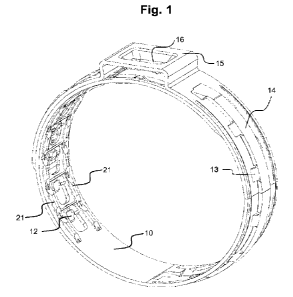
pipe nipple.
[0002] A hose clamp is known from WO 2017/005283 Al,
in which an ear-like tightening
device is formed in the clamping band, the ear-like tightening device being
formed by two
radially outward protruding legs and a bar connecting them. An appropriate
preforming of
the tightening device can allow the hose clamp to be set onto the hose with as
little
clearance as possible. The clamp is then tightened and plastically deformed
against the
elastic resilience of the preformed tightening device, whereby a narrow and
tight fixation of
the hose to the pipe nipple is achieved.
[0003] In the mounted state, an outer section of the
clamping band, which also includes
the outward protruding tightening device, overlaps an inner clamping band
section. After
the hose clamp has been fastened, a portion of the inner clamping band section
is located
immediately below the tightening device. This portion, situated between the
two legs of the
tightening device in the outer band section, is, contrary to its two
neighbouring portions
where the inner band section is reinforced by the immediately adjacent outer
band section,
less protected against buckling in the radial direction or also torsions.
Summary of the invention
[0004] The invention is based on the general object
of at least partially eliminating disad-
vantages that occur in comparable hose clamps according to the state of the
art. A more
specific object of the invention can be seen in the provision of a hose clamp
with adjustable
diameter having an improved protection against buckling of the clamping band
upon
bending in the radial direction or against other torsions.
[0005] The solution to this problem is achieved with
the hose clamp specified in Claim
1. In this hose clamp, at least one corrugated bead extending between the
edges of the
clamping band and parallel to them is formed on the inner band section of the
clamping
band, so that at least a part of the corrugated bead is located below the
tightening device
in the closed state of the clamping band. In particular, two corrugated beads
extending
parallel to each other can be arranged on both lateral peripheries of the
clamping band on
the inner band section.
1
CA 03156897 2022-5-2
[0006] By engaging pulling hooks and corresponding
positioning hooks in the clamping
band, the diameter of the hose clamp in the mounted state can be adjusted
within a certain
range. Depending on which of the pulling and positioning hooks are engaged
with each
other, different portions of the clamping band end up in the position below
the tightening
device in the mounted state. It is therefore advisable to have the corrugated
bead or the
corrugated beads extend over a section of the clamping band including all
portions which
could possibly end up in the position below the tightening device with for an
appropriate
diameter of the hose clamp.
[0007] The corrugated bead is formed as a sequence
of elongated bead depressions in
the sheet metal of the clamping band. In view of their purpose, these
depressions are
pressed perpendicularly and inwardly in the radial direction into the sheet
metal of the
clamping band, so that they protrude into the hose material in the mounted
state and
enhance the hold of the hose clamp to the hose in this state as well as before
and upon
fastening. During mounting as well as subsequently in operation, the
corrugated beads with
their wave shape are effective against a contortion of the hose clamp on the
hose.
Furthermore, the interruptions between the individual depressions of the
corrugated beads
facilitate the forming of the clamping band by hand, which is advantageous for
manufacturing as well as for mounting.
[0008] It is also conceivable to form the corrugated
bead perpendicularly and outwardly
in the radial direction in the clamping band, whereby the additional pressure
on the hose
can be avoided; in this case, the part of the corrugated bead or the
corrugated beads
extending beyond the tightening device presses against the innerface of the
outer clamping
band section. It may therefore be advisable to form corresponding longitudinal
beads
projecting outwardly for accommodating the corrugated beads in the part of the
outer
clamping band section adjacent to the tightening device.
[0009] In addition to improving bending strength,
the corrugated beads also contribute
to an increase in tensile strength and thus to an improved force reception in
perimeter
direction, thereby resulting in an improved overall stability of the hose
clamp.
Drawings
[0010] An embodiment of the invention is explained
in more detail below with reference
to the drawings. Here:
Figure 1 is a perspective view of a hose clamp according to an embodiment of
the invention in the closed state,
Figure 2 is a further perspective view of the hose clamp in the closed state
from
another viewing angle,
2
CA 03156897 2022-5-2
Figure 3 shows the hose clamp in the stretched initial state, viewed from the
outer side in the closed state, and
Figure 4 shows the hose clamp in the stretched initial state, viewed from the
inner
side in the closed state.
Embodiment
[0011] The hose clamp according to an embodiment of
the invention and shown in
Figures 1 and 2 consists of an open clamping band 10 which consists of,
starting from the
inner clamping band end, a tongue 11, a row of positioning hooks 12 (in the
example as
shown, seven), a band arch 14 cut out from the clamping band 10 by two
parallel
longitudinal cuts and connected to side parts of the clamping band 10 via
flaps 13, a
tightening device 15 in the form of a so-called ''Oetiker" ear with a pair of
outwardly cranked
legs and a bar connecting them and reinforced by a bead 16, a release hood 17,
as well
as three pulling hooks 19 and opening caps 18 in the other outer band section.
[0012] Such a hose clamp is intended in particular
for sealing and fastening bellows,
for example for use in cardan shafts, made of thermoplastic materials or other
materials of
high Shore hardness that are hard to deform.
[0013] In use, the hose clamp which is supplied by
the manufacturer in the closed state,
is pulled axially onto the item to be tied, such as a pipe nipple and a hose
surrounding it or,
alternatively, opened for radial assembly and placed around the material to be
tied, with
the tongue 11 ending up positioned under the band arch 14.
[0014] The three pulling hooks 19 in the outer band
section are then engaged with the
positioning hooks 12 arranged in the inner band section, which correspond to
the smallest
possible diameter of the respective material to be tied.
[0015] In the example shown, there are three pulling
hooks 19. Depending on the force
and strength requirements, two pulling hooks or a single pulling hook may be
sufficient or
more than three pulling hooks 19 may be required.
[0016] The number of positioning hooks 12 is greater
than that of the pulling hooks 19
in order to allow for a corresponding range of variation in the clamp
diameter. In the
embodiment shown, seven positioning hooks 12 are provided. In Figure 1, the
hose clamp
is closed at a medium diameter. For the smallest closed diameter, the middle
one of the
seven positioning hooks 12 would in this case be underneath the release cap
17, and the
three positioning hooks 12 towards the band middle would be in engagement with
the three
pulling hooks 19.
3
CA 03156897 2022-5-2
[0017] The hose clamp according to the invention
comprises two corrugated beads 21
extending in the longitudinal direction. The corrugated beads 21 extend in
parallel to each
other at the side edges 10 of the clamping band in a region from the tongue 11
to the last
one of the positioning hooks 12. This region is chosen such that independently
of the
diameter with which the hose clamp is fixed on the hose, it can be ensured
that a respective
part of the corrugated beads 21 is positioned below the tightening device 15
in the mounted
state. Depending on the configuration of the hose clamp, also another region
for the
corrugated bead, in particular a smaller or larger region, can satisfy this
criterion.
[0018] As shown in particular in Figures 3 and 4,
each positioning hook 12 is arranged
in a clearance window 20 cut out from the clamping band 10. It comprises a lug
which is
connected to the clamping band 10 at its edge facing away from the tightening
device 15
and which extends essentially in parallel to the clamping band 10. At the
transition to the
lug, a step is formed radially inwardly and facing away from the tightening
device 15.
[0019] The pulling hooks 19 are each curved dome-
like radially inwards and have a lug
which engages over the lug of the positioning hook 12. The opening cap 18,
which is formed
radially outwards on the opposite side of the pulling hook, provides the
necessary space
for the positioning hook 12, so that the lug of the pulling hook 19 can engage
over the lug
21 of the positioning hook 12. At the transition to the lug, a step is formed
radially outwards
and facing the tightening device 15.
[0020] The lugs of the positioning and pulling hooks
12, 19 hold the outer and inner
clamping band sections on top of each other, while the force is transmitted
between
transverse surfaces of the pulling hooks 19, which are transverse to the
longitudinal
direction of the clamping band 10, and transverse surfaces of the positioning
hooks 12,
which are transverse to the longitudinal direction of the clamping band 10,
when the hose
clamp is tightened.
[0021] Depending on the configuration length of the
lugs, the step of the positioning
hook 12 can abut with the free end of the lug of the pulling hook 19 and the
step of the
pulling hook 19 can abut with thefree end of the lug of the positioning hook
12 in the closed
state of the hose clamp, which generates a secondary force transmission
location and
results in a mutual stabilisation of the hooks arranged on the inner band
section and the
outer band section.
[0022] In the closed state of the hose clamp, three
of the positioning hooks 12 are in
engagement with the pulling hooks 19. Depending on the hose diameter, the
positioning
hooks for the engagement with the pulling hooks are selected such as to ensure
the desired
tight closure. On the tongue side, a part of the inner end of the band reaches
the position
4
CA 03156897 2022-5-2
underneath the tightening device 15. The lateral corrugated beads 21 provided
in the
appropriate part of the clamping band 10 stabilise the clamping band 10
against buckling
in the radial direction underneath the tightening device 15. The corrugated
beads 21 can
be configured in the form of interrupted grooves or as a series of individual
beads. On both
sides of the clamping band 10, they merge into continuous groove-shaped
reinforcement
beads 22 (alternatively or additionally, the corrugated beads can also be
continued as such
continuous reinforcement beads in the direction towards the tightening
device).
[0023] In addition to the corrugated beads 21,
lateral reinforcement beads 23 in
continuous groove shape are provided in the embodiment in the region of the
band arch 14
which forms a tongue channel for the tongue and receives it in the closed
state. Breakage
frequently occurs in the region of the band arch 14, so that additional
reinforcement beads
23 can contribute here effectively to a stabilization of the band arch region.
[0024] In the present embodiment, the continuous
reinforcement beads 22, 23 are
provided both in the area of the positioning hooks 12 and in the area of the
band arch 14
in order to jointly contribute to the overall stability of the hose clamp.
However, it is also
conceivable to provide in addition to the corrugated beads 21 only the
reinforcement beads
22 or only the reinforcement beads 23.
[0025] In the embodiment, the pulling hooks 19 und
opening hoods 18 are further sur-
rounded by reinforcement beads stamped into the clamping band 10, which
increase the
bending stiffness for any given material strength and which allow the
transmission of larger
forces.
[0026] For the same reason, the clearance windows 20
of the positioning hooks 12 are
stiffened by embossments between the windows 20 and the side edges of the
clamping
band 10.
CA 03156897 2022-5-2
Reference numbers
clamping band
11 tongue
12 positioning hook
13 flaps
14 band arch
tightening device
16 bead
17 release cap
18 opening hood
19 pulling hook
clearance window
21 corrugated bead
22 reinforcement bead
23 reinforcement bead
6
CA 03156897 2022-5-2