Note: Descriptions are shown in the official language in which they were submitted.
CA 03157147 2022-04-05
[DESCRIPTION]
[INVENTION TITLE]
FUEL CELL HUMIDIFIER
[TECHNICAL FIELD]
[1] The present disclosure relates to a humidifier for
fuel cells configured to supply humidified gas to a fuel cell.
[Background Art]
[2] A fuel cell has advantages in that it is possible to
continuously generate electricity as long as hydrogen and
oxygen are supplied, unlike a general chemical cell, such as
a dry cell or a storage cell, and in that there is no heat
loss, whereby efficiency of the fuel cell is about twice as
high as efficiency of an internal combustion engine.
[3] In addition, the fuel cell directly converts chemical
energy generated by combination of hydrogen and oxygen into
electrical energy, whereby the amount of contaminants that
are discharged is small. Consequently, the fuel cell has
advantages in that the fuel cell is environmentally friendly
and in that a concern about depletion of resources due to an
increase in energy consumption can be reduced.
[4] Based on the kind of an electrolyte that is used,
such a fuel cell may be classified as a polymer electrolyte
membrane fuel cell (PEMFC), a phosphoric acid fuel cell
1
Date Recue/Date Received 2022-04-05
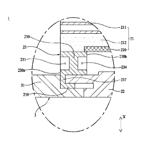
CA 03157147 2022-04-05
(PAFC), a molten carbonate fuel cell (MCFC), a solid oxide
fuel cell (SOFC), or an alkaline fuel cell (AFC).
[5] These fuel cells are operated fundamentally by the
same principle, but are different from each other in terms
of the kind of fuel that is used, operating temperature,
catalyst, and electrolyte. Among
these fuel cells, the
polymer electrolyte membrane fuel cell (PEMFC) is known as
being the most favorable to a transportation system as well
as small-scale stationary power generation equipment, since
the polymer electrolyte membrane fuel cell is operated at a
lower temperature than the other fuel cells and the output
density of the polymer electrolyte membrane fuel cell is high,
whereby it is possible to miniaturize the polymer electrolyte
membrane fuel cell.
[6] One of the most important factors in improving the
performance of the polymer electrolyte membrane fuel cell
(PEMFC) is to supply a predetermined amount or more of
moisture to a polymer electrolyte membrane or a proton
exchange membrane (PEM) of a membrane electrode assembly (MEA)
in order to retain moisture content. The reason for this is
that, if the polymer electrolyte membrane or the proton
exchange membrane is dried, power generation efficiency is
abruptly reduced.
[7] 1) A bubbler humidification method of filling a
pressure-resistant container with water and allowing a target
2
Date Recue/Date Received 2022-04-05
CA 03157147 2022-04-05
gas to pass through a diffuser in order to supply moisture,
2) a direct injection method of calculating the amount of
moisture to be supplied that is necessary for fuel cell
reaction and directly supplying moisture to a gas stream pipe
through a solenoid valve, and 3) a membrane humidification
method of supplying moisture to a gas fluid bed using a
polymer separation membrane are used as methods of
humidifying the polymer electrolyte membrane or the proton
exchange membrane.
[8] Among these methods, the membrane humidification
method, which provides water vapor to air that is supplied
to the polymer electrolyte membrane or the proton exchange
membrane using a membrane configured to selectively transmit
only water vapor included in off-gas in order to humidify
the polymer electrolyte membrane or the proton exchange
membrane, is advantageous in that it is possible to reduce
the weight and size of a humidifier.
[9] When a module is formed, a hollow fiber membrane
having large transmission area per unit volume is suitable
for a permselective membrane used in the membrane
humidification method. That is, when a humidifier is
manufactured using a hollow fiber membrane, high integration
of the hollow fiber membrane having large contact surface
area is possible, whereby it is possible to sufficiently
humidify the fuel cell even at a small capacity, it is
3
Date Recue/Date Received 2022-04-05
CA 03157147 2022-04-05
possible to use a low-priced material, and it is possible to
collect moisture and heat included in off-gas discharged from
the fuel cell at a high temperature and to reuse the collected
moisture and heat through the humidifier.
[10] FIG. 1 is a schematic exploded perspective view of a
conventional humidifier for fuel cells.
[11] As illustrated in FIG. 1, a conventional membrane
humidification type humidifier 100 includes a humidifying
module 110, in which moisture exchange is performed between
air supplied from the outside and off-gas discharged from a
fuel cell stack (not shown), and caps 1200 coupled
respectively to opposite ends of the humidifying module 110.
[12] One of the caps 120 transmits air supplied from the
outside to the humidifying module 110, and the other cap
transmits air humidified by the humidifying module 110 to
the fuel cell stack.
[13] The humidifying module 110 includes a mid-case 111
having an off-gas inlet 111a and an off-gas outlet 111b and
a plurality of hollow fiber membranes 112 in the mid-case
111. Opposite ends of a bundle of hollow fiber membranes
112 are potted in fixing layers 113. In
general, each of
the fixing layers 113 is formed by hardening a liquid polymer,
such as liquid polyurethane resin, using a casting method.
[14] Air supplied from the outside flows along hollow
parts of the hollow fiber membranes 112. Off-gas introduced
4
Date Recue/Date Received 2022-04-05
CA 03157147 2022-04-05
into the mid-case 111 through the off-gas inlet 111a comes
into contact with the outer surfaces of the hollow fiber
membranes 112, and is discharged from the mid-case 111
through the off-gas outlet 111b. When the off-gas comes into
contact with the outer surfaces of the hollow fiber membranes
112, moisture contained in the off-gas is transmitted through
the hollow fiber membranes 112 to humidify air flowing along
the hollow parts of the hollow fiber membranes 112.
[15] Inner spaces of the caps 120 must fluidly communicate
with only the hollow parts of the hollow fiber membranes 112
in a state of being completely isolated from an inner space
of the mid-case 111. If not, air leakage due to pressure
difference occurs, whereby the amount of humidified air that
is supplied to the fuel cell stack is reduced and power
generation efficiency of a fuel cell is lowered.
[16] In general, as illustrated in FIG. 1, the fixing
layers 113, in which opposite ends of the hollow fiber
membranes 112 are potted, and resin layers 114 provided
between the fixing layers 113 and the mid-case 111 isolate
the inner spaces of the caps 120 from the inner space of the
mid-case 111. Similarly to the fixing layers 113, each of
the resin layers 114 is generally formed by hardening a
liquid polymer, such as liquid polyurethane resin, using a
casting method.
[17] However, a casting process for forming the resin
Date Recue/Date Received 2022-04-05
CA 03157147 2022-04-05
layers 114 requires a relatively long process time, whereby
productivity of the humidifier 100 is lowered.
[Disclosure]
[Technical Problem]
[18] The present disclosure has been made in view of the
above problems, and it is an object of the present
disclosure to provide a humidifier for fuel cells capable of
preventing lowering in productivity of the humidifier due to
formation of a resin layer through a casting process.
[Technical Solution]
[19] In order to accomplish the above object, the present
disclosure may include the following construction.
[20] A humidifier for fuel cells according to the present
disclosure may include a humidifying module configured to
humidify dry gas supplied from outside using wet gas
discharged from a fuel cell stack and a first cap coupled to
one end of the humidifying module. The humidifying module
may include a mid-case and at least one cartridge disposed
in the mid-case, the cartridge being configured to receive a
plurality of hollow fiber membranes. The humidifier for fuel
cells according to the present disclosure may further include
a first packing member airtightly coupled to at least one
end of the humidifying module through mechanical assembly
6
Date Recue/Date Received 2022-04-05
CA 03157147 2022-04-05
such that the first cap fluidly communicates with only the
hollow fiber membranes. The
first packing member may be
brought into tight contact with the cartridge using pressure
of at least one of dry gas and wet gas.
[Advantageous Effects]
[21] The present disclosure is implemented such that a
casting process for hermetically sealing an inner space of a
cap and an inner space of a mid-case is omitted. In the
present disclosure, therefore, it is possible to improve
productivity through reduction in process time for production.
[22] In the present disclosure, it is possible to increase
hermetic sealing force using the pressure of at least one
of dry gas and wet gas. Also, in the present disclosure,
it is possible to increase hermetic sealing force without an
additional construction, whereby it is possible to reduce
cost necessary to increase hermetic sealing force.
[Description of Drawings]
[23] FIG. 1 is a schematic exploded perspective view of a
conventional humidifier for fuel cells.
[24] FIG. 2 is a schematic exploded perspective view of a
humidifier for fuel cells according to the present disclosure.
[25] FIG. 3 is a schematic exploded sectional view showing
the humidifier for fuel cells according to the present
7
Date Recue/Date Received 2022-04-05
CA 03157147 2022-04-05
disclosure, taken along line I-I of FIG. 2.
[26] FIG. 4 is a schematic coupled sectional view showing
the humidifier for fuel cells according to the present
disclosure, taken along line I-I of FIG. 2.
[27] FIG. 5 is a schematic enlarged sectional view showing
part A of FIG. 4.
[28] FIGS. 6 to 9 are schematic enlarged sectional views
showing a first packing member, taken along line I-I of FIG.
2.
[29] FIG. 10 is a schematic exploded perspective view
showing an embodiment in which two cartridges are coupled to
a mid-case in the humidifier for fuel cells according to the
present disclosure.
[30] FIG. 11 is a schematic enlarged sectional view
showing the first packing member, taken along line II-II of
FIG. 10.
[31] FIGS. 12 and 13 are schematic enlarged sectional
views showing the state in which the first packing member
and a second packing member are coupled to the mid-case and
the cartridges, taken along line II-II of FIG. 10.
[32] FIG. 14 is a schematic exploded perspective view
showing an embodiment in which three cartridges are coupled
to the mid-case in the humidifier for fuel cells according
to the present disclosure.
[33] FIG. 15 is a schematic enlarged sectional view
8
Date Recue/Date Received 2022-04-05
CA 03157147 2022-04-05
showing part A of FIG. 4.
[34] FIGS. 16 to 18 are schematic enlarged sectional views
showing the first packing member, taken along line I-I of
FIG. 2.
[35] FIG. 19 is a schematic enlarged sectional view
showing the state in which the first packing member and the
second packing member are coupled to the mid-case and the
cartridges, taken along line II-II of FIG. 10.
[36] FIGS. 20 and 21 are schematic enlarged sectional
views showing part A of FIG. 4.
[37] FIGS. 22 to 24 are schematic enlarged sectional views
showing the state in which the first packing member and the
second packing member are coupled to the mid-case and the
cartridges, taken along line II-II of FIG. 10.
[Best Mode]
[38] Hereinafter, embodiments of a humidifier for fuel
cells according to the present disclosure will be described
in detail with reference to the accompanying drawings.
[39] Referring to FIGS. 2 to 4, a humidifier 1 for fuel
cells according to the present disclosure humidifies dry gas
supplied from the outside using wet gas discharged from a
fuel cell stack. The dry gas may be fuel gas or air.
[40] The humidifier 1 for fuel cells according to the
present disclosure includes a humidifying module 2 configured
9
Date Recue/Date Received 2022-04-05
CA 03157147 2022-04-05
to humidify dry gas and a first cap 3 coupled to one end of
the humidifying module 2. The humidifying module 2 includes
a cartridge 21, to which a plurality of hollow fiber
membranes 211 is coupled, a mid-case 22, to which the
cartridge 21 is coupled, and a first packing member 23
disposed between the cartridge 21 and the mid-case 22 to
hermetically seal between the cartridge 21 and the mid-case
22. The
first packing member 23 may hermetically seal
between the cartridge 21 and the mid-case 22 through coupling
without a casting process. Consequently, the first packing
member 23 may hermetically seal an inner space of the first
cap 3 and an inner space of the mid-case 22. In the
humidifier 1 for fuel cells according to the present
disclosure, therefore, the casting process, which requires a
relatively long process time, may be omitted, whereby it is
possible to improve productivity through reduction in process
time for production.
[41] Hereinafter, the humidifying module 2 and the first
cap 3 will be described in detail with reference to the
accompanying drawings.
[42] Referring to FIGS. 2 to 4, the humidifying module 2
humidifies dry gas supplied from the outside using wet gas
discharged from the fuel cell stack. The first cap 3 may be
coupled to one end of the humidifying module 2. A second
cap 4 may be coupled to the other end of the humidifying
Date Recue/Date Received 2022-04-05
CA 03157147 2022-04-05
module 2. The first cap 3 may transmit dry gas supplied from
the outside to the humidifying module 2. The second cap 4
may transmit the dry gas humidified by the humidifying module
2 to the fuel cell stack. The second cap 4 may transmit dry
gas supplied from the outside to the humidifying module 2,
and the first cap 3 may transmit the dry gas humidified by
the humidifying module 2 to the fuel cell stack.
[43] The humidifying module 2 includes the cartridge 21,
the mid-case 22, and the first packing member 23.
[44] The cartridge 21 includes the plurality of hollow
fiber membranes 211. The hollow fiber membranes 211 may be
implemented as the cartridge 21 so as to be modularized.
Consequently, the hollow fiber membranes 211 may be installed
in the mid-case 22 through a process of coupling the
cartridge 21 to the mid-case 22. In the
humidifier 1 for
fuel cells according to the present disclosure, therefore,
ease in installation, separation, and replacement of the
hollow fiber membranes 211 may be improved. The cartridge
21 may include an inner case 210 configured to receive the
hollow fiber membranes 211. The hollow fiber membranes 211
may be disposed in the inner case 210 so as to be modularized.
Each of the hollow fiber membranes 211 may include a polymer
membrane made of polysulfone resin, polyethersulfone resin,
sulfonated polysulfone resin, polyvinylidene fluoride (PVDF)
resin, polyacrylonitrile (PAN) resin, polyimide resin,
11
Date Recue/Date Received 2022-04-05
CA 03157147 2022-04-05
polyamide imide resin, polyester imide resin, or a mixture
of two or more thereof.
[45] The cartridge 21 may include a first potting portion
212. The first potting portion 212 fixes the hollow fiber
membranes 211. The first potting portion 212 may fix one
side of each of the hollow fiber membranes 211. In this
case, the first potting portion 212 may be formed so as not
to block hollow portions of the hollow fiber membranes 211.
The first potting portion 212 may be formed by hardening a
liquid resin, such as liquid polyurethane resin, using a
casting process. The first potting portion 212 may fix the
inner case 210 and one side of each of the hollow fiber
membranes 211 to each other.
[46] The cartridge 21 may include a second potting
portion 213. The second potting portion 213 fixes the other
side of each of the hollow fiber membranes 211. In this
case, the second potting portion 213 may be formed so as not
to block the hollow portions of the hollow fiber membranes
211. Consequently, dry gas may be supplied to the hollow
portions of the hollow fiber membranes 211, may be humidified,
and may be supplied to the fuel cell stack without being
disturbed by the second potting portion 213 and the first
potting portion 212. The second potting portion 213 may be
formed by hardening a liquid resin, such as liquid
polyurethane resin, using a casting process. The
second
12
Date Recue/Date Received 2022-04-05
CA 03157147 2022-04-05
potting portion 213 may fix the inner case 210 and the other
side of each of the hollow fiber membranes 211 to each other.
[47] The cartridge 21 is coupled to the mid-case 22. The
cartridge 21 may be disposed in the mid-case 22 such that a
space is defined between the inner surface of the mid-case
22 and the outer surface of the cartridge 21. The mid-case
22 may include an inlet 221 and an outlet 222. Wet gas
containing moisture may be introduced into the mid-case 22
through the inlet 221, and may then come into contact with
the outer surfaces of the hollow fiber membranes 211. During
this process, the moisture contained in the wet gas may be
transmitted through the hollow fiber membranes 211, whereby
the dry gas flowing along the hollow portions of the hollow
fiber membranes 211 may be humidified. The humidified dry
gas may be discharged from the hollow fiber membranes 211,
and may then be supplied to the fuel cell stack. After
humidifying the dry gas, the wet gas may be discharged from
the mid-case 22 through the outlet 222. The inlet 221 may
be connected to the fuel cell stack. In this case, the wet
gas may be off-gas discharged from the fuel cell stack.
[48] Meanwhile, the cartridge 21 may be provided with an
introduction hole (not shown) configured to allow the wet
gas to be introduced therethrough and a discharge hole (not
shown) configured to allow the wet gas, after humidifying
the dry gas flowing along the hollow portions of the hollow
13
Date Recue/Date Received 2022-04-05
CA 03157147 2022-04-05
fiber membranes 211, to be discharged therethrough. In this
case, the wet gas may be introduced between the inner surface
of the mid-case 22 and the outer surface of the cartridge 21
through the inlet 221, may be introduced into the cartridge
21 through the introduction hole, may humidify the dry gas
flowing along the hollow portions of the hollow fiber
membranes 211, may be discharged between the inner surface
of the mid-case 22 and the outer surface of the cartridge 21
through the discharge hole, and may be discharged from the
mid-case 22 through the outlet 222.
[49]
Referring to FIGS. 2 to 6, the first packing member
23 hermetically seals between the cartridge 21 and the mid-
case 22. The
first packing member 23 may be airtightly
coupled to at least one end of the humidifying module 2
through mechanical assembly.
Consequently, the first
packing member 23 allows the first cap 3 to fluidly
communicate with only the hollow fiber membranes 112.
Consequently, the first packing member 23 may prevent direct
mixing between dry gas to be supplied to the fuel cell stack
and wet gas supplied into the mid-case 22. The first packing
member 23 may be inserted between the cartridge 21 and the
mid-case 22. In this case, the cartridge 21 may be inserted
into a first passing hole 23a formed in the first packing
member 23. The first packing member 23 may contact each of
an inner wall of the mid-case 22, an outer wall of the
14
Date Recue/Date Received 2022-04-05
CA 03157147 2022-04-05
cartridge 21, and the first potting portion 212. Through
such contact, the first packing member 23 may be airtightly
coupled to one end of the humidifying module 2. In this
case, the first packing member 23 may contact each of a
portion of the inner wall of the mid-case 22, a portion of
the outer wall of the cartridge 21, and a portion of the
first potting portion 212.
[50] The
humidifier 1 for fuel cells according to the
present disclosure may include a plurality of first packing
members 23. The
first packing members 23 and 23' may be
airtightly coupled to opposite ends of the humidifying module
2, respectively. In this case, the first packing members 23
and 23' may be disposed at opposite sides of the cartridge
21. The first packing member 23' may contact each of the
inner wall of the mid-case 22, the outer wall of the cartridge
21, and the second potting portion 213, whereby the first
packing member 23' may be airtightly coupled to the other
end of the humidifying module 2. In this
case, the first
packing member 23' may contact each of a portion of the inner
wall of the mid-case 22, a portion of the outer wall of the
cartridge 21, and a portion of the second potting portion
213. Since
the first packing members 23 and 23' are
implemented so as to have the same structure except that the
positions thereof are different from each other, a
description will be given based on the first packing member
Date Recue/Date Received 2022-04-05
CA 0=147 2022-04-05
23 disposed at one end of the humidifying module 2. It is
obvious to those skilled in the art to which the present
disclosure pertains that the first packing member 23'
disposed at the other end of the humidifying module 2 is
derived therefrom.
[51] The
first packing member 23 may be brought into
tight contact with the cartridge 21 using the pressure of
at least one of dry gas and wet gas. During a humidification
process, both the dry gas and the wet gas flow at a
considerable pressure, whereby each of the dry gas and the
wet gas has pressure sufficient to press the first packing
member 23 toward the cartridge 21.
Consequently, the
humidifier 1 for fuel cells according to the present
disclosure is implemented such that the first packing member
23 is brought into tight contact with the cartridge 21 using
the pressure of at least one of the dry gas and the wet gas
during the humidification process. In the humidifier 1 for
fuel cells according to the present disclosure, therefore,
it is possible to implement hermetic sealing force necessary
to prevent direct mixing between the dry gas and the wet gas
without an additional construction, whereby it is possible
to reduce cost necessary to increase hermetic sealing force.
The first packing member 23 may be made of an elastically
deformable material. For example, the first packing member
23 may be made of rubber. The first packing member 23 may
16
Date Recue/Date Received 2022-04-05
CA 0=147 2022-04-05
be formed in a ring shape so as to hermetically seal between
the cartridge 21 and the mid-case 22.
[52] The first packing member 23 may include a first
packing body 230. The first packing body 230 defines the
overall external appearance of the first packing member 23.
When the first packing body 230 is inserted between the
cartridge 21 and the mid-case 22, a first outer surface 230a
of the first packing body 230 may be disposed so as to face
the first cap 3. In this case, a first inner surface 230b
of the first packing body 230 may be disposed so as to face
the interior of the mid-case 22. The first inner surface
230b and the first outer surface 230a may be disposed so as
to face in opposite directions.
[53] The first packing member 23 may include a first
outer groove 231 and a first outer member 232.
[54] The first outer groove 231 receives dry gas. The
first outer groove 231 may be formed in the first outer
surface 230a. Consequently, the first outer groove 231 may
be disposed so as to face the first cap 3, and therefore
the first outer groove may receive dry gas located between
the first cap 3 and the cartridge 21.
[55] The first outer member 232 contacts the cartridge
21 between the first outer groove 231 and the cartridge 21.
Depending on the pressure of the dry gas received in the
first outer groove 231, the first outer member 232 may be
17
Date Recue/Date Received 2022-04-05
CA 0=147 2022-04-05
pressed toward the cartridge 21, and therefore the first
outer member may be brought into tight contact with the
cartridge 21. In the humidifier 1 for fuel cells according
to the present disclosure, therefore, it is possible to
increase hermetic sealing force between the first packing
member 23 and the cartridge 21 using the pressure of the dry
gas received in the first outer groove 231. The first outer
member 232 may be brought into tight contact with the first
potting portion 212.
[56] The first packing member 23 may include a first
outer protrusion 233. The first outer protrusion 233
contacts the mid-case 22 between the first outer groove 231
and the mid-case 22. Depending on the pressure of the dry
gas received in the first outer groove 231, the first outer
protrusion 233 may be pressed toward the mid-case 22, and
therefore the first outer protrusion may be brought into
tight contact with the mid-case 22. In the humidifier 1 for
fuel cells according to the present disclosure, therefore,
it is possible to increase hermetic sealing force between
the first packing member 23 and the mid-case 22 using the
pressure of the dry gas received in the first outer groove
231.
[57] When the first packing member 23 includes both the
first outer member 232 and the first outer protrusion 233,
the first outer groove 231 may be disposed between the first
18
Date Recue/Date Received 2022-04-05
CA 03157147 2022-04-05
outer member 232 and the first outer protrusion 233 in a
first-axis direction (X-axis direction). Consequently, the
pressure of the dry gas received in the first outer groove
231 may act in a direction in which the distance between
the first outer member 232 and the first outer protrusion
233 is increased. Using the pressure of the dry gas received
in the first outer groove 231, therefore, the first outer
member 232 may be brought into tight contact with the
cartridge 21, and the first outer protrusion 233 may be
brought into tight contact with the mid-case 22. The first
outer member 232, the first outer protrusion 233, and the
first packing body 230 may be integrally formed.
[58] The first packing member 23 may include a first
inner groove 234 and a first inner member 235.
[59] The first inner groove 234 receives wet gas. The
first inner groove 234 may be formed in the first inner
surface 230b. Consequently, the first inner groove 234 may
be disposed so as to face the interior of the mid-case 22,
and therefore the first inner groove may receive wet gas
located in the mid-case 22. In this case, wet gas located
between the inner surface of the mid-case 22 and the outer
surface of the cartridge 21 may be received in the first
inner groove 234.
[60] The first inner member 235 contacts the cartridge
21 between the first inner groove 234 and the cartridge 21.
19
Date Recue/Date Received 2022-04-05
CA 0=147 2022-04-05
Depending on the pressure of the wet gas received in the
first inner groove 234, the first inner member 235 may be
pressed toward the cartridge 21, and therefore the first
inner member may be brought into tight contact with the
cartridge 21. In the humidifier 1 for fuel cells according
to the present disclosure, therefore, it is possible to
increase hermetic sealing force between the first packing
member 23 and the cartridge 21 using the pressure of the wet
gas received in the first inner groove 234. The first inner
member 235 may be brought into tight contact with the inner
case 210. A portion of the first inner member 235 may be
brought into tight contact with the first potting portion
212, and a portion of the first inner member may also be
brought into tight contact with the inner case 210.
[61] The
first packing member 23 may include a first
inner protrusion 236. The
first inner protrusion 236
contacts the mid-case 22 between the first inner groove 234
and the mid-case 22. Depending on the pressure of the wet
gas received in the first inner groove 234, the first inner
protrusion 236 may be pressed toward the mid-case 22, and
therefore the first inner protrusion may be brought into
tight contact with the mid-case 22. In the humidifier 1 for
fuel cells according to the present disclosure, therefore,
it is possible to increase hermetic sealing force between
the first packing member 23 and the mid-case 22 using the
Date Recue/Date Received 2022-04-05
CA 03157147 2022-04-05
pressure of the wet gas received in the first inner groove
234.
[62] When the first packing member 23 includes both the
first inner member 235 and the first inner protrusion 236,
the first inner groove 234 may be disposed between the first
inner member 235 and the first inner protrusion 236.
Consequently, the pressure of the wet gas received in the
first inner groove 234 may act in a direction in which the
distance between the first inner member 235 and the first
inner protrusion 236 is increased. Using the pressure of
the wet gas received in the first inner groove 234,
therefore, the first inner member 235 may be brought into
tight contact with the cartridge 21, and the first inner
protrusion 236 may be brought into tight contact with the
mid-case 22. The first inner member 235, the first inner
protrusion 236, and the first packing body 230 may be
integrally formed.
[63] The first packing member 23 may include an extension
member 237 and a catching member 238.
[64] The extension member 237 extends toward the mid-
case 22. The extension member 237 may extend from the first
outer protrusion 233 toward the mid-case 22. The extension
member 237 may be supported by the mid-case 22. The
extension member 237 may connect the catching member 238
and the first outer protrusion 233 to each other. The
21
Date Recue/Date Received 2022-04-05
CA 03157147 2022-04-05
extension member 237, the catching member 238, the first
outer protrusion 233, and the first packing body 230 may be
integrally formed. The extension member 237 may extend from
the first packing body 230 toward the mid-case 22.
[65] A catching groove 237a may be formed in the
extension member 237. The
catching groove 237a may be
disposed between the first outer protrusion 233 and the
catching member 238. The mid-case 22 may be inserted into
the catching groove 237a.
[66] The catching member 238 is coupled to the extension
member 237. The catching member 238 may be disposed outside
of the mid-case 22 inserted into the catching groove 237a.
In this case, the mid-case 22 may be disposed between the
catching member 238 and the first outer protrusion 233. The
mid-case 22 may also be disposed between the catching member
238 and the first packing body 230.
[67] Since the first packing member 23 is coupled to the
mid-case 22 by catching, as described above, the depth by
which the first packing member 23 is inserted into the mid-
case 22 may be limited during the process of increasing
hermetic sealing force using the pressure of at least one
of the dry gas and the wet gas. In the
humidifier 1 for
fuel cells according to the present disclosure, therefore,
it is possible to improve stability in increasing hermetic
sealing force using the pressure of at least one of the dry
22
Date Recue/Date Received 2022-04-05
CA 03157147 2022-04-05
gas and the wet gas.
[68] Referring to FIG. 7, the first packing member 23
may include a first reinforcement member 239. The
first
reinforcement member 239 may be disposed in the first
packing body 230. The first reinforcement member 239 may
be made of a material that has higher rigidity than the
first packing body 230. For
example, the first
reinforcement member 239 may be made of metal or plastic.
The first reinforcement member 239 may be implemented so as
to be disposed in the first packing body 230 by insert
molding.
[69] As shown in FIGS. 5 to 7, the first packing member
23 may be implemented so as to include all of the first
outer groove 231, the first outer member 232, the first
outer protrusion 233, the first inner groove 234, the first
inner member 235, and the first inner protrusion 236. As
shown in FIG. 8, the first packing member 23 may be
implemented so as to include only the first outer groove
231, the first outer member 232, and the first outer
protrusion 233. As shown
in FIG. 9, the first packing
member 23 may be implemented so as to include only the first
inner groove 234, the first inner member 235, and the first
inner protrusion 236.
[70] Referring to FIGS. 2 to 9, the first cap 3 is coupled
to one end of the humidifying module 2. The space between
23
Date Recue/Date Received 2022-04-05
CA 03157147 2022-04-05
the first cap 3 and the cartridge 21 may be isolated from
the space between the cartridge 21 and the mid-case 22 in a
hermetically sealed state by the first packing member 23.
[71] The first cap 3 may include a first pushing member
31. When the
first cap 3 is coupled to one end of the
humidifying module 2, the first pushing member 31 may push
the extension member 237 toward the mid-case 22.
Consequently, the first pushing member 31 may further
increase fixing force necessary for the first packing member
23 to be maintained in a state of hermetically sealing
between the cartridge 21 and the mid-case 22.
[72] Referring to FIGS. 2 to 4, the second cap 4 is
coupled to the other end of the humidifying module 2. The
space between the second cap 4 and the cartridge 21 may be
isolated from the space between the cartridge 21 and the
mid-case 22 in a hermetically sealed state by the first
packing member 23'. The
first packing member 23' is
approximately identical to the first packing member 23
described above, and a detailed description thereof will be
omitted.
[73] Referring to FIGS. 10 to 13, the humidifier 1 for
fuel cells according to the present disclosure may be
implemented such that a plurality of cartridges 21 is coupled
in the mid-case 22. In this case, the mid-case 22 may include
a partition member (not shown) disposed between the
24
Date Recue/Date Received 2022-04-05
CA 03157147 2022-04-05
cartridges 21 and 21'. The
cartridges 21 and 21' may be
individually detachably coupled to the mid-case 22 in a state
of being disposed between the partition members. Meanwhile,
in FIGS. 11 to 13, only the first potting portion is shown
with omission of a plurality of hollow fiber membranes and
an inner case, although each of the cartridges 21 and 21'
includes the plurality of hollow fiber membranes and the
inner case.
[74] When the humidifying module 2 is implemented such
that the plurality of cartridges 21 is coupled to the mid-
case 22, the humidifying module may include a second packing
member 24.
[75] The second packing member 24 is disposed between the
cartridges 21 and 21' to hermetically seal between the
cartridges 21 and 21'. The
second packing member 24 may
prevent direct mixing between dry gas and wet gas through
the space between the cartridges 21 and 21'. The humidifier
1 for fuel cells according to the present disclosure may
include a plurality of second packing members 24. The second
packing members 24 and 24' may be disposed at opposite sides
of the cartridges 21 and 21'. Since
the second packing
members 24 and 24' are implemented so as to have the same
structure except that the positions thereof are different
from each other, a description will be given based on the
second packing member 24 disposed at one side of each of the
Date Recue/Date Received 2022-04-05
CA 03157147 2022-04-05
cartridges 21 and 21'. It is
obvious to those skilled in
the art to which the present disclosure pertains that the
second packing member 24' disposed at the other side of each
of the cartridges 21 and 21' is derived therefrom.
[76] The second packing member 24 may be brought into
tight contact with the cartridges 21 and 21' using the
pressure of at least one of dry gas and wet gas. In the
humidifier 1 for fuel cells according to the present
disclosure, therefore, it is possible to implement hermetic
sealing force necessary to prevent direct mixing between the
dry gas and the wet gas through the space between the
cartridges 21 and 21' without an additional construction,
whereby it is possible to reduce cost necessary to increase
hermetic sealing force. The second packing member 24 may
be made of an elastically deformable material. For example,
the second packing member 24 may be made of rubber.
[77] The second packing member 24 may include a second
packing body 240. The second packing body 240 defines the
overall external appearance of the second packing member 24.
When the second packing body 240 is inserted between the
cartridges 21 and 21', a second outer surface 240a of the
second packing body 240 may be disposed so as to face the
first cap 3. In this case, a second inner surface 240b of
the second packing body 240 may be disposed so as to face
the interior of the mid-case 22. When a partition member
26
Date Recue/Date Received 2022-04-05
CA 03157147 2022-04-05
is provided in the mid-case 22, the second inner surface
240b may be disposed so as to face the partition member.
The second inner surface 240b and the second outer surface
240a may be disposed so as to face in opposite directions.
[78] The second packing member 24 may include a second
outer groove 241 and a plurality of second outer members
242 and 242'.
[79] The second outer groove 241 receives dry gas. The
second outer groove 241 may be formed in the second outer
surface 240a.
Consequently, the second outer groove 241
may be disposed so as to face the first cap 3, and therefore
the first outer groove may receive dry gas located between
the first cap 3 and the cartridge 21.
[80] The second outer members 242 and 242' contact the
cartridges 21 and 21' between the second outer groove 241
and the cartridges 21 and 21'. Depending on the pressure
of the dry gas received in the second outer groove 241, the
second outer members 242 and 242' may be pressed toward the
cartridges 21 and 21', and therefore the second outer
members may be brought into tight contact with the
cartridges 21 and 21', respectively. In the
humidifier 1
for fuel cells according to the present disclosure, therefore,
it is possible to increase hermetic sealing force between
the second packing member 24 and the cartridges 21 and 21'
using the pressure of the dry gas received in the second
27
Date Recue/Date Received 2022-04-05
CA 03157147 2022-04-05
outer groove 241. The
second outer members 242 and 242'
may be brought into tight contact with the first potting
portion 212. The second outer groove 241 may be disposed
between the second outer members 242 and 242'. Consequently,
the pressure of the dry gas received in the second outer
groove 241 may act in a direction in which the distance
between the second outer members 242 and 242' is increased.
The second outer members 242 and 242' and the second packing
body 240 may be integrally formed.
[81] The second packing member 24 may include a second
inner groove 243 and second inner members 244 and 244'.
[82] The second inner groove 243 receives wet gas. The
second inner groove 243 may be formed in the second inner
surface 240b. Consequently, the second inner groove 243
may be disposed so as to face the interior of the mid-case
22, and therefore the first inner groove may receive wet
gas located in the mid-case 22. In this
case, wet gas
located between the outer surfaces of the cartridges 21 and
21' may be received in the second inner groove 243.
[83] The second inner members 244 and 244' contact the
cartridges 21 and 21' between the second inner groove 243
and the cartridges 21 and 21'. Depending on the pressure
of the wet gas received in the second inner groove 243, the
second inner members 244 and 244' may be pressed toward the
cartridges 21 and 21', and therefore the second inner
28
Date Recue/Date Received 2022-04-05
CA 03157147 2022-04-05
members may be brought into tight contact with the
cartridges 21 and 21', respectively. In the
humidifier 1
for fuel cells according to the present disclosure, therefore,
it is possible to increase hermetic sealing force between
the second packing member 24 and the cartridges 21 and 21'
using the pressure of the wet gas received in the second
inner groove 243. The
second inner members 244 and 244'
may be brought into tight contact with the inner cases 210
of the cartridges 21 and 21', respectively. A portion of
each of the second inner members 244 and 244' may be brought
into tight contact with a corresponding one of the first
potting portions 212 and 212' of the cartridges 21 and 21',
and a portion of each of the second inner members may be
brought into tight contact with a corresponding one of the
inner cases 210 of the cartridges 21 and 21'. The second
inner groove 243 may be disposed between the second inner
members 244 and 244'.
Consequently, the pressure of the
wet gas received in the second inner groove 243 may act in
a direction in which the distance between the second inner
members 244 and 244' is increased. The second inner members
244 and 244' and the second packing body 240 may be
integrally formed.
[84] Here,
the second packing member 24 and the first
packing member 23 may be integrally formed. Consequently,
the second packing member 24 and the first packing member
29
Date Recue/Date Received 2022-04-05
CA 0=147 2022-04-05
23 may be installed through single insertion. In the
humidifier 1 for fuel cells according to the present
disclosure, therefore, it is possible to improve ease in
hermetically sealing between the mid-case 22 and the
cartridge 21 and between the cartridges 21 even when the
plurality of cartridges 21 is coupled to the mid-case 22.
[85] Referring to FIG. 13, the second packing member 24
may include a second reinforcement member 245. The second
reinforcement member 245 may be disposed in the second
packing body 240. The second reinforcement member 245 may
be made of a material that has higher rigidity than the
second packing body 240. For
example, the second
reinforcement member 245 may be made of metal or plastic.
The second reinforcement member 245 may be implemented so
as to be disposed in the second packing body 240 by insert
molding.
[86] As shown in FIGS. 11 to 13, the second packing
member 24 may be implemented so as to include all of the
second outer groove 241, the second outer members 242 and
242', the second inner groove 243, and the second inner
members 244 and 244'. Although
not shown, the second
packing member 24 may be implemented so as to include only
the second outer groove 241 and the second outer members
242 and 242'. Although not shown, the second packing member
24 may be implemented so as to include only the second inner
Date Recue/Date Received 2022-04-05
CA 03157147 2022-04-05
groove 243 and the second inner members 244 and 244'.
[87] FIGS. 10
to 13 show that two cartridges 21 are
coupled to the mid-case 22. However, the present disclosure
is not limited thereto. As shown in FIG. 14, the humidifier
1 for fuel cells according to the present disclosure may be
implemented such that three cartridges 21, 21', and 21" are
coupled to the mid-case 22. In this case, two second packing
members 24 may be provided at one side of the humidifying
module 2, and two second packing members 24' may be provided
at the other side of the humidifying module 2. Although
not shown, the humidifier 1 for fuel cells according to the
present disclosure may be implemented such that four or more
cartridges 21 are coupled to the mid-case 22. In this case,
the number of second packing members 24 and 24' may be
increased in proportion to the number of cartridges 21
coupled to the mid-case 22.
[88]
Referring to FIGS. 15 and 16, the humidifying module
2 may include a first elastic member 25. In this case, the
first packing member 23 may be brought into tight contact
with the cartridge 21 using elastic force of the first
elastic member 25. In the
humidifier 1 for fuel cells
according to the present disclosure, therefore, it is
possible to increase hermetic sealing force necessary to
prevent direct mixing between the dry gas and the wet gas
using the first elastic member 25. In the humidifier 1 for
31
Date Recue/Date Received 2022-04-05
CA 03157147 2022-04-05
fuel cells according to the present disclosure, therefore,
it is possible to improve stability in humidifying the dry
gas.
[89] The first elastic member 25 is coupled to the first
packing member 23. The first elastic member 25 may bring
the first packing member 23 into tight contact with the
cartridge 21 using elastic force thereof. The first elastic
member 25 may be implemented as a spring having elastic
force. The first elastic member 25 may be formed in a ring
shape.
[90] The first elastic member 25 may be inserted into
the first outer groove 231. In this case, the first elastic
member 25 may press the first outer member 232 toward the
cartridge 21 using elastic force thereof, whereby the first
outer member 232 may be brought into tight contact with the
cartridge 21. In the humidifier 1 for fuel cells according
to the present disclosure, therefore, it is possible to
increase hermetic sealing force between the first packing
member 23 and the cartridge 21 using the elastic force of
the first elastic member 25. In this case, the first outer
member 232 may be pressed toward the cartridge 21 by the
elastic force of the first elastic member 25, and therefore
the first outer member may be brought into tight contact
with the cartridge 21. The first outer member 232 may be
brought into tight contact with the first potting portion
32
Date Recue/Date Received 2022-04-05
CA 03157147 2022-04-05
212.
[91] When the
first packing member 23 includes the first
outer groove 231 and the first outer member 232, the first
packing member 23 may be brought into tight contact with the
cartridge 21 using the pressure of dry gas. During
the
humidification process, both the dry gas and the wet gas
flow at a considerable pressure, whereby the dry gas has
pressure sufficient to press the first packing member 23
toward the cartridge 21. Consequently, the humidifier 1 for
fuel cells according to the present disclosure is implemented
such that the first packing member 23 is brought into tighter
contact with the cartridge 21 using the pressure of the dry
gas during the humidification process, in addition to using
the elastic force of the first elastic member 25. In the
humidifier 1 for fuel cells according to the present
disclosure, therefore, it is possible to further increase
hermetic sealing force necessary to prevent direct mixing
between the dry gas and the wet gas. Also, in the humidifier
1 for fuel cells according to the present disclosure, it is
possible to further increase hermetic sealing force without
an additional construction, since the pressure of the dry
gas is used. In the humidifier 1 for fuel cells according
to the present disclosure, therefore, it is possible to
reduce cost necessary to further increase hermetic sealing
force.
33
Date Recue/Date Received 2022-04-05
CA 0=147 2022-04-05
[92] When the first packing member 23 is brought into
tight contact with the cartridge 21 using the elastic force
of the first elastic member 25 and the pressure of the dry
gas, as described above, the first outer groove 231 may
receive the dry gas located between the first cap 3 and the
cartridge 21. The
first outer member 232 may be pressed
toward the cartridge 21 depending on the pressure of the
dry gas received in the first outer groove 231, whereby the
first outer member may be brought into tight contact with
the cartridge 21.
[93] As shown in FIG. 16, the first elastic member 25 may
be disposed in the first packing body 230. In this
case,
the first elastic member 25 may press the first packing body
230 toward the cartridge 21 using the elastic force thereof,
whereby the first packing body 230 may be brought into tight
contact with the cartridge 21. Consequently, the humidifier
1 for fuel cells according to the present disclosure is
implemented such that the first outer member 232 is brought
into tight contact with the cartridge 21 using the pressure
of the dry gas received in the first outer groove 231 and
such that the first packing body 230 is brought into tight
contact with the cartridge 21 using the elastic force of the
first elastic member 25. In the humidifier 1 for fuel cells
according to the present disclosure, therefore, different
portions of the first packing member 23 may be brought into
34
Date Recue/Date Received 2022-04-05
CA 03157147 2022-04-05
tight contact with the cartridge 21, whereby it is possible
to increase hermetic sealing force through a dual structure.
The first elastic member 25 may be implemented so as to be
disposed in the first packing body 230 by insert molding.
[94]
Referring to FIG. 17, the first elastic member 25
may be disposed at the first inner surface 230b such that
the first packing member 23 is brought into tight contact
with the cartridge 21. The first elastic member 25 may be
inserted into the first inner groove 234 so as to contact
the first inner member 235. Consequently, the first elastic
member 25 may bring the first inner member 235 into tight
contact with the cartridge 21 using the elastic force
thereof. In the
humidifier 1 for fuel cells according to
the present disclosure, therefore, it is possible to increase
hermetic sealing force between the first packing member 23
and the cartridge 21 using the elastic force of the first
elastic member 25. In this case, the first inner member 235
may be pressed toward the cartridge 21 by the elastic force
of the first elastic member 25, whereby the first inner
member may be brought into tight contact with the cartridge
21. The first inner member 235 may be brought into tight
contact with the inner case 210. A portion of the first
inner member 235 may be brought into tight contact with the
first potting portion 212, and a portion of the first inner
member may be brought into tight contact with the inner case
Date Recue/Date Received 2022-04-05
CA 0=147 2022-04-05
210.
[95] When the first packing member 23 includes the first
inner groove 234 and the first inner member 235, the first
packing member 23 may be brought into tight contact with the
cartridge 21 using the pressure of wet gas. Consequently,
the humidifier 1 for fuel cells according to the present
disclosure is implemented such that the first packing member
23 is brought into tighter contact with the cartridge 21
using the pressure of the wet gas during the humidification
process, in addition to using the elastic force of the first
elastic member 25.
[96] When the first packing member 23 is brought into
tight contact with the cartridge 21 using the elastic force
of the first elastic member 25 and the pressure of the wet
gas, as described above, the first inner groove 234 may
receive the wet gas located between the first cap 3 and the
cartridge 21. The first inner member 235 may be pressed
toward the cartridge 21 depending on the pressure of the
wet gas received in the first inner groove 234, whereby the
first inner member may be brought into tight contact with
the cartridge 21.
[97] Although not shown, the first packing member 23 may
also be implemented such that the first outer member 232 is
brought into tight contact with the cartridge 21 by the
elastic force of the first elastic member 25 disposed in
36
Date Recue/Date Received 2022-04-05
CA 0=147 2022-04-05
the first outer groove 231 and such that the first inner
member 235 is brought into tight contact with the cartridge
21 by the pressure of the wet gas received in the first
inner groove 234. In this case, the first outer member 232
may also be brought into tight contact with the cartridge
21 by the elastic force of the first elastic member 25 and
the pressure of the dry gas received in the first outer
groove 231.
[98] Although not shown, the first packing member 23 may
also be implemented such that the first inner member 235 is
brought into tight contact with the cartridge 21 by the
elastic force of the first elastic member 25 disposed in
the first outer groove 231 and such that the first outer
member 232 is brought into tight contact with the cartridge
21 by the pressure of the dry gas received in the first
outer groove 231. In this case, the first inner member 235
may also be brought into tight contact with the cartridge
21 by the elastic force of the first elastic member 25 and
the pressure of the wet gas received in the first inner
groove 234.
[99] Although not shown, the first packing member 23 may
also be implemented such that the first packing body 230 is
brought into tight contact with the cartridge 21 by the
elastic force of the first elastic member 25 disposed in
the first packing body 230 and such that the first inner
37
Date Recue/Date Received 2022-04-05
CA 03157147 2022-04-05
member 235 is brought into tight contact with the cartridge
21 by the pressure of the wet gas received in the first
inner groove 234.
[100] Although not shown, the first packing member 23 may
also be implemented such that the first packing body 230 is
brought into tight contact with the cartridge 21 by the
elastic force of the first elastic member 25 disposed in
the first packing body 230, such that the first outer member
232 is brought into tight contact with the cartridge 21 by
the pressure of the dry gas received in the first outer
groove 231, and such that the first inner member 235 is
brought into tight contact with the cartridge 21 by the
pressure of the wet gas received in the first inner groove
234.
[101] Referring to FIG. 18, the humidifying module 2 may
include a second elastic member 26.
[102] The second elastic member 26 is coupled to the first
packing member 23. The second elastic member 26 may bring
the first packing member 23 into tight contact with the
cartridge 21 using elastic force thereof. The
second
elastic member 26 may be implemented as a spring having
elastic force. The second elastic member 26 may be formed
in a ring shape.
[103] The second elastic member 26 may be inserted into
the first inner groove 234. In this case, the second elastic
38
Date Recue/Date Received 2022-04-05
CA 03157147 2022-04-05
member 26 may press the first inner member 235 toward the
cartridge 21 using elastic force thereof, whereby the first
inner member 235 may be brought into tight contact with the
cartridge 21. In this
case, the first elastic member 25
may bring the first outer member 232 into contact with the
cartridge 21 using the elastic force thereof in a state of
being disposed in the first outer groove 231.
[104] In the
humidifier 1 for fuel cells according to the
present disclosure, therefore, the first inner member 235
and the first outer member 232 may be brought into tight
contact with the cartridge 21 using the elastic force of the
second elastic member 26 and the elastic force of the first
elastic member 25. In the
humidifier 1 for fuel cells
according to the present disclosure, therefore, different
portions of the first packing member 23 may be brought into
tight contact with the cartridge 21, whereby it is possible
to increase hermetic sealing force through a dual structure.
In this case, the first inner member 235 may be brought into
tighter contact with the cartridge 21 by the elastic force
of the second elastic member 26 and the pressure of the wet
gas received in the first inner groove 234. The first outer
member 232 may be brought into tighter contact with the
cartridge 21 by the elastic force of the first elastic
member 25 and the pressure of the dry gas received in the
first outer groove 231.
39
Date Recue/Date Received 2022-04-05
CA 03157147 2022-04-05
[105] Although not shown, one of the second elastic member
26 and the first elastic member 25 may be disposed in the
first packing body 230, and the other elastic member may be
disposed in one of the first inner groove 234 and the first
outer groove 231.
[106] Referring to FIGS. 10 and 19, the humidifying module
2 may include a plurality of first elastic members 25. The
first elastic members 25 and 25' may be inserted
respectively into the first outer groove 231 and the second
outer groove 241 to bring the first packing member 23 and
the second packing member 24 into tight contact with the
cartridges 21 and 21', respectively. The
first elastic
members 25 and 25' may be disposed so as to surround the
cartridges 21 and 21', respectively, to elastically press
the first packing member 23 and the second packing member
24 toward the cartridges 21 and 21', respectively.
Consequently, the humidifier 1 for fuel cells according to
the present disclosure is implemented such that the first
packing member 23 and the second packing member 24 are
brought into tight contact with the cartridges 21 and 21',
respectively, using the pressure of the dry gas received in
the first outer groove 231 and the second outer groove 241
and the elastic force of the first elastic members 25 and
25'. In the
humidifier 1 for fuel cells according to the
present disclosure, therefore, it is possible to increase
Date Recue/Date Received 2022-04-05
CA 03157147 2022-04-05
hermetic sealing force through a dual structure.
[107] The humidifying module 2 may further include a
plurality of second elastic members 26, in addition to the
first elastic members 25 and 25'. The
second elastic
members 26 and 26' may be inserted respectively into the
first inner groove 234 and the second inner groove 243 to
bring the first packing member 23 and the second packing
member 24 into tight contact with the cartridges 21 and 21',
respectively. The second elastic members 26 and 26' may be
disposed so as to surround the cartridges 21 and 21',
respectively, to elastically press the first packing member
23 and the second packing member 24 toward the cartridges
21 and 21', respectively.
Consequently, the humidifier 1
for fuel cells according to the present disclosure is
implemented such that the first packing member 23 and the
second packing member 24 are brought into tight contact with
the cartridges 21 and 21', respectively, using the pressure
of the dry gas received in the first inner groove 234 and
the second inner groove 243 and the elastic force of the
second elastic members 26 and 26'. In the humidifier 1 for
fuel cells according to the present disclosure, therefore,
it is possible to further increase hermetic sealing force.
[108] Although not shown, the humidifying module 2 may be
implemented such that the first elastic members 25 and 25'
are inserted respectively into the first inner groove 234
41
Date Recue/Date Received 2022-04-05
CA 03157147 2022-04-05
and the second inner groove 243 to bring the first packing
member 23 and the second packing member 24 into tight
contact with the cartridges 21 and 21', respectively. The
first elastic members 25 and 25' may be inserted
respectively into the first inner groove 234 and the second
inner groove 243 so as to surround the cartridges 21 and
21', respectively, whereby the first packing member 23 and
the second packing member 24 may be elastically pressed
toward the cartridges 21 and 21', respectively.
[109] Referring to FIGS. 2, 20, and 21, the cartridge 21
may include a first support 214. The first packing member
23 may be implemented so as to be brought into tight contact
with the cartridge 21 in a state of being compressed through
interference fit using the first support 214.
[110] The first support 214 may be coupled to the first
potting portion 212. The first support 214 may be disposed
so as to surround the periphery of the first potting portion
212. As a result, the first potting portion 212 may be
disposed inside the first support 214. The first support
214 may be formed in a ring shape. The first support 214
may be disposed so as to protrude to the outside of the
first potting portion 212. During insertion of the first
packing member 23 between the mid-case 22 and the cartridge
21, therefore, the portion of the first packing member 23
disposed between the mid-case 22 and the first support 214
42
Date Recue/Date Received 2022-04-05
CA 0=147 2022-04-05
may be compressed as the result of interference fit.
Consequently, it is possible to further increase hermetic
sealing force using the first packing member 23.
[111] The first support 214 may be supported by the inner
case 210 through hook coupling such that movement of the
first support in a second-axis direction (Y-axis direction)
is limited. The second-axis direction (Y-axis direction)
is an axis direction perpendicular to the first-axis
direction (X-axis direction) and is an axis direction
parallel to a direction in which the first cap 3 and the
second cap 4 are spaced apart from each other. In the state
in which the first support 214 is coupled to the inner case
210, the first potting portion 212 may be formed through a
casting process, whereby the first support 214 may be
implemented so as to be coupled to the first potting portion
212.
Afterwards, the first packing member 23 may be
inserted between the cartridge 21 and the mid-case 22. The
first support 214 may be made of a material that has higher
rigidity than the first packing member 23. For
example,
the first support 214 may be made of metal or plastic.
[112] The first support 214 may be implemented so as to
be shorter than the first packing member 23 in the second-
axis direction (Y-axis direction). For example, as shown
in FIG. 20, the first support 214 may be implemented such
that the first support 214 is not present between the first
43
Date Recue/Date Received 2022-04-05
CA 03157147 2022-04-05
outer member 232 and the first potting portion 212 but is
present only between the first packing body 230 and the
first potting portion 212. Consequently, the first outer
member 232 may be pressed by the pressure of the dry gas
received in the first outer groove 231, whereby the first
outer member may be brought into tight contact with the
first potting portion 212. The first packing body 230 may
be compressed between the mid-case 22 and the first support
214 as the result of interference fit, whereby the first
packing body may be brought into tight contact with the
first support 214.
[113] The
first support 214 may be implemented so as to
have the same length as the first packing member 23 or to
have a larger length than the first packing member 23 in
the second-axis direction (Y-axis direction). For example,
as shown in FIG. 21, the first support 214 may be implemented
such that the first support 214 is present between the first
outer member 232 and the first potting portion 212 and is
also present between the first packing body 230 and the
first potting portion 212. Consequently, the first outer
member 232 and the first packing body 230 may be compressed
between the mid-case 22 and the first support 214 as the
result of interference fit, whereby the first outer member
and the first packing body may be brought into tight contact
with the first support 214. In this case, the first outer
44
Date Recue/Date Received 2022-04-05
CA 03157147 2022-04-05
member 232 may be brought into tight contact with the
cartridge 21 by both pressing by the first support 214 and
the pressure of the dry gas received in the first outer
groove 231.
[114] When the first support 214 is implemented so as to
contact both the first outer member 232 and the first
packing body 230, the first support 214 may be used as a
potting cap during formation of the first potting portion
212 through a casting process. In this case, as indicated
by a dotted line in FIG. 21, the first potting portion 212
is formed through a casting process in the state in which
the first support 214 is coupled to the inner case 210 so
as to be implemented as a potting cap, and then the cartridge
21 may be manufactured through a cutting process of cutting
a portion CP of the first support 214 and a portion of the
first potting portion 212 such that the hollow portions of
the hollow fiber membranes 211 are opened. In an embodiment
in which the first support 214 is used as the potting cap,
a potting cap assembly process and a potting cap removal
process may be omitted, compared to a comparative example
using a separate potting cap. In the embodiment in which
the first support 214 is used as the potting cap, therefore,
it is possible to reduce manufacturing cost and to improve
productivity through shortening of a manufacturing time.
[115] The cartridge 21 may include a second support (not
Date Recue/Date Received 2022-04-05
CA 03157147 2022-04-05
shown). The second support may be coupled to the second
potting portion 213. Since the second support and the first
support 214 are implemented so as to have the same structure
except that the positions thereof are different from each
other, it is obvious to those skilled in the art to which
the present disclosure pertains that the structure of the
second support can be understood from the description of
the first support 214.
Therefore, a detailed description
of the second support will be omitted.
[116]
Referring to FIG. 2 and 21, the first cap 3 may
include a first pushing protrusion 32. The first pushing
protrusion 32 protrudes from the first pushing member 31.
When the first cap 3 is coupled to one end of the humidifying
module 2, the first pushing protrusion 32 may push the
extension member 237 toward the mid-case 22, whereby the
extension member 237 may be brought into tight contact with
the mid-case 22. Consequently, the first pushing protrusion
32 may further increase hermetic sealing force between the
first cap 3 and the mid-case 22 and may further increase
force that fixes the first packing member 23. The
first
pushing protrusion 32 may be formed such that the size of
the first pushing protrusion is gradually decreased as the
first pushing protrusion protrudes from the first pushing
member 31. The first pushing protrusion 32 may be formed
in a ring shape.
46
Date Recue/Date Received 2022-04-05
CA 03157147 2022-04-05
[117] The first cap 3 may include a first supporting
member 33. The first supporting member 33 may be inserted
into the first outer groove 231 to support the first packing
body 230. Consequently, the first supporting member 33 may
limit movement of the first packing member 23, whereby it
is possible to prevent separation of the first packing
member 23 due to vibration and shaking. The
first
supporting member 33 may be formed so as to have a length
capable of pressing the first packing body 230. In this
case, the first supporting member 33 may press the first
packing body 230 such that the first outer groove 231 is
maintained in a state of having a size sufficient to receive
a fluid for cells. In addition, the first supporting member
33 may press the first packing body 230 in order to further
increase tight contact force by which the first packing
member 23 is brought into tight contact with the cartridge
21. The first supporting member 33 may be formed in a ring
shape.
[118] Although not shown, the second cap 4 may include a
second pushing member, a second pushing protrusion, and a
second supporting member. The second pushing member, the
second pushing protrusion, and the second supporting member
are implemented so as to be approximately identical
respectively to the first pushing member 31, the first
pushing protrusion 32, and the first supporting member 33
47
Date Recue/Date Received 2022-04-05
CA 0=147 2022-04-05
described above, and therefore a detailed description
thereof will be omitted.
[119] Referring to FIGs. 22 to 24, when the humidifying
module 2 includes a plurality of cartridges 21 and 21', the
cartridges 21 and 21' may include the first supports 214
and 214', respectively. Each of the first supports 214 and
214' may be disposed so as to surround the periphery of a
corresponding one of the cartridges 21 and 21'. During
insertion of the second packing member 24 between the
cartridges 21 and 21', therefore, the portion of the second
packing member 24 disposed between the first supports 214
and 214' may be extruded as the result of interference fit.
Consequently, hermetic sealing force using the second
packing member 24 may be further increased. Each of the
first supports 214 and 214' may be made of a material that
has higher rigidity than the second packing member 24. For
example, each of the first supports 214 and 214' may be made
of metal or plastic.
[120] Each of the first supports 214 and 214' may be
implemented so as to be shorter than the second packing
member 24 in the second-axis direction (Y-axis direction).
For example, as shown in FIGS. 22 and 23, the first supports
214 and 214' may be implemented such that the first supports
214 and 214' are not present between the second outer
members 242 and 242' and the first potting portions 212 and
48
Date Recue/Date Received 2022-04-05
CA 03157147 2022-04-05
212' but are present only between the second packing body
240 and the first potting portions 212 and 212'.
Consequently, the second outer members 242 and 242' may be
pressed by the pressure of the dry gas received in the
second outer groove 241, whereby the second outer members
may be brought into tight contact with the first potting
portions 212 and 212', respectively. The
second packing
body 240 may be compressed between the first supports 214
and 214' as the result of interference fit, whereby the
second packing body may be brought into tight contact with
the first supports 214 and 214'.
[121] Each of
the first supports 214 and 214' may be
implemented so as to have the same length as the second
packing member 24 or to have a larger length than the second
packing member 24 in the second-axis direction (Y-axis
direction). For
example, as shown in FIG. 24, the first
supports 214 and 214' may be implemented such that the first
supports 214 and 214' are present between the second outer
members 242 and 242' and the first potting portions 212 and
212' and are also present between the second packing body
240 and the first potting portions 212 and 212'.
Consequently, the second outer members 242 and 242' and the
second packing body 240 may be compressed between the first
supports 214 and 214' as the result of interference fit,
whereby the second outer members and the second packing body
49
Date Recue/Date Received 2022-04-05
CA 0=147 2022-04-05
may be brought into tight contact with the first supports
214 and 214'. In this
case, the second outer members 242
and 242' may be brought into tight contact with the
cartridges 21 and 21', respectively, by both pressing by
the first supports 214 and 214' and the pressure of the dry
gas received in the second outer groove 241.
[122] The present disclosure described above is not
limited to the above embodiments and the accompanying
drawings, and it will be obvious to a person having ordinary
skill in the art to which the present disclosure pertains
that various substitutions, modifications, and alterations
are possible without departing from the technical idea of
the present disclosure.
Date Recue/Date Received 2022-04-05