Note: Descriptions are shown in the official language in which they were submitted.
CA 03157802 2022-04-11
WO 2021/080807 PCT/US2020/055292
SNOW REMOVAL APPARATUS AND METHOD
BACKGROUND OF THE INVENTION
1. Field of the Invention
[0001] The present invention relates to an apparatus for removing snow or
debris from a
substrate such as a road surface. More particularly, the present invention
relates to a snow
removal apparatus that effectively removes snow or other debris from a
substrate while
minimizing damage to the surface and maximizing the quality and quantity of
snow removal.
2. Description of the Prior Art
[0002] Present ways to remove snow from roadways or other substrates involve
the use of a
structure that makes contact with the substrate wherein the structure is
shaped or positioned to
push the snow from that portion of the substrate in contact with the
apparatus. That contact with
the substrate can cause damage to the surface and to matter adjacent to the
substrate. As an
example, private, commercial and municipal snowplow operations employ trucks
and tractors to
support and move snowplow blades. Those snowplow blades are made of rigid
material and may
be singular and maneuverable or they may be split blades with two
independently operable
blades that can be manipulated up and down and angled. Generally, snowplow
blades tend to be
removably affixed to the front end of the vehicle although in some instances
they may be
supported on the undercarriage of certain types of tractors.
[0003] Regardless of the particular vehicle and the particular blade
configuration, the blade
devices are weighted or otherwise configured to remain in contact with the
roadway so that a
substantial portion of any snow accumulating on the roadway in the path of the
blade is pushed
aside sufficient to make the roadway passable. Given that most every roadway
has some sort of
imperfection, it is essentially a given that the roadway, the blade or both
will be damaged over
the course of a snow removal season. In addition, structures peripheral to the
roadway are also
exposed to blade contact including, but not limited to, guardrails, curbs, and
paint striping. As a
result, there is substantial repair work required after each snow removal
season. That repair
work includes maintenance for the plow blades due to wear and tear. In
addition, the energy
required to remove snow is minimized based on the resistance and friction
associated with
making contact with the underlying substrate.
1
CA 03157802 2022-04-11
WO 2021/080807 PCT/US2020/055292
[0004] On a smaller scale, snowblowers are also used to remove snow. However,
they are
operated at slower speeds than are snowplows, they generally remove
substantially less snow per
hour and their repair requirements are substantial. While snowblowers may have
their place in a
localized setting, they are not adequate for large-scale roadway snow removal.
[0005] What is needed is a snow removal apparatus that is configured to
minimize substrate
damage when in use without compromising the snow removal function. What is
also needed is a
snow removal apparatus that is configured to effectively remove snow in a
manner that
minimizes the energy required and damage to equipment and to the substrate
while completing
the function, removes more snow per pass and can move at higher speeds than
can conventional
snowplows. Such an apparatus may not be limited to removing snow only but may
also be used
to remove other substrate debris.
SUMMARY OF THE INVENTION
[0006] It is an object of the present invention to provide a snow removal
apparatus that is
configured to minimize substrate damage when in use without compromising the
snow removal
quality function. It is also an object to provide such a snow removal
apparatus that is configured
to effectively remove snow in a manner that minimizes the energy required to
complete the snow
removal function.
[0007] Currently, between 1/4 inch and two inches of snow is left on portions
of the roadway
between passes and covered with salt and/or sand to increase traction. The
present invention is
capable of removing all snow on the roadway between passes at a higher rate of
speed that
accomplishes more clearing per hour. A benefit of the invention is the cleaner
roadway that
results per pass at a higher speed with less need for the use of salt and/or
sand. The ability to
proceed at higher speed helps force air and lift snow into the invention's
chute to move that snow
off the roadway. The air pressure and volume of air delivered by the invention
to snow on the
roadway is proportional to the velocity of the vehicle propelling the
invention.
[0008] These and other objects are achieved with the present invention, which
is an apparatus
that causes the displacement of snow from the roadway without making direct
physical contact
with the roadway. Instead, the invention establishes an invisible "blade of
air" in the form of a
forced air port that directs a pressure front of air at high velocity
sufficient to dislodge and lift
snow from the roadway surface. A second vacuum port draws dislodged and lifted
snow into the
2
CA 03157802 2022-04-11
WO 2021/080807 PCT/US2020/055292
apparatus's housing using Bernoulli's Principle and the Venturi effect. That
is, a second port is
used to push air through a linear shaped ejector jet at a rate sufficient to
produce a vacuum to
draw the lifted snow into a chamber referred to herein as a collection chute
or an exit chute. The
housing includes one or more blowers and/or fans arranged to produce air flow
in plenums
associated with the air blade port and the vacuum port with an exit chute away
from the roadway.
[0009] The apparatus also includes a conventional type of plow blade. That
plow blade is used
to push snow away that is at a selectable height above the roadway so that the
blade does not
contact the roadway directly. Instead, the air blade and the vacuum port
remove the snow that
remains in place below the bottom of the blade. The apparatus is of a
selectable width.
BRIEF DESCRIPTION OF THE DRAWINGS
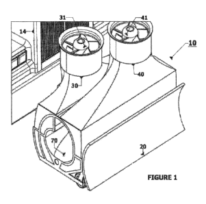
[0010] FIG. 1 is an isometric front view of the snow removal apparatus of the
present invention
attached to a vehicle that can be used to move the apparatus.
[0011] FIG. 2 is a side view of the present invention attached to the vehicle
showing the
roadway traffic side of the apparatus.
[0012] FIG. 3 is a rear bottom isometric view of the apparatus on the roadway
shoulder side of
the apparatus.
[0013] FIG. 4 is a front bottom isometric bottom view of the apparatus on the
roadway shoulder
side of the apparatus.
[0014] FIG. 5 is a front view of the apparatus.
[0015] FIG. 6 is a first sectional side view of the apparatus.
[0016] FIG. 7 is a second sectional side view of the apparatus.
[0017] FIG. 8 is a third sectional side view of the apparatus.
DETAILED DESCRIPTION OF THE PRESENT INVENTION
[0018] A snow removal apparatus 10 of the present invention is shown in FIGS.
1-8. The
apparatus 10 is removably attachable by a coupling 12 to a vehicle 14, wherein
the vehicle 14
may be used to transport the apparatus 10 over a roadway surface 16 covered
with snow 18. The
coupling 12 may be a typical adapter of the type used to attach a plow to a
vehicle. The
apparatus 10 is used to remove the snow from the surface 16. It is
contemplated that the
apparatus 10 may be used to remove other material residing on the surface 16
not limited to the
3
CA 03157802 2022-04-11
WO 2021/080807 PCT/US2020/055292
snow 18. While the apparatus 10 is shown attached to the front of the vehicle
14, it is to be
understood that the apparatus 10 may be towed behind a vehicle such as vehicle
14 but not
limited thereto. That is, the apparatus 10 may be coupled to the front of a
vehicle or to the rear
of a vehicle.
[0019] The apparatus 10 includes a plow 20 a first air transport unit 30, a
second air transport
unit 40, a blade of air outlet 50, a Venturi vacuum jet 60 and a collection
chute 70. The
components of the apparatus 10 are arranged to remove an upper portion of the
snow 18 with the
plow 20, lift the remaining portion of the snow 18 in contact with the surface
16 using the first
air transport unit 30 and the blade of air outlet 50, and pushes the lifted
snow into the collection
chute 70 using the second air transport unit 40 and the Venturi vacuum jet 60.
The lifted snow
located in the collection chute 70 will be forced out of the apparatus 10
through an open end
thereof adjacent to the shoulder side of the roadway via gravity and
accumulated air pressure.
[0020] The plow 20 may be of any type suitable for snow removal. It is
removably attachable to
housing 100 that contains the collection chute 70. One or more offset wheels
110 are removably
attached to the housing 100 and/or the plow 20 in an arrangement that
maintains plow bottom 22
raised above the surface 16 while the apparatus 10 is in use. The positioning
of the plow bottom
22 above the surface 16 is selectable based on the extent to which the one or
more offset wheels
110 lift the plow 20 but it should be raised sufficiently to minimize the
possibility of having the
plow 20 make direct contact with the surface 16 when the apparatus 10 is in
use.
[0021] The first air transport unit 30 is positioned above or adjacent to the
collection chute 70
and includes a blower assembly 31, an air delivery plenum 32 and a blade
plenum 33. The first
air transport unit 30 is arranged so that blower assembly 31 is operated to
draw air into blower
inlet 34 for entry into the air delivery plenum 32. The blower assembly 31
includes a motor or
other Power Delivery System (PDS) 35 and blades, impeller, airscrew or other
compressor 36,
now referred to as a blower. The blower assembly 31 is operable by one or more
controllers
coupled to a console and/or computer within the vehicle 14 so that activation
of the PDS 35
causes the blower 36 to move in a direction that draws air into the inlet 34.
The air delivery
plenum 32 is shaped to cause the incoming air to be distributed along the
width of the apparatus
10, corresponding approximately with the selectable width of the plow 20.
[0022] The air delivery plenum 32 transitions at location 37 to the blade
plenum 33. The blade
plenum 33 is of a shape having a width substantially the same as the width of
the air delivery
4
CA 03157802 2022-04-11
WO 2021/080807 PCT/US2020/055292
plenum 32 but a continually decreasing cross sectional area into the blade
plenum 33. This
narrowing to the blade plenum 33 quickly accelerates the velocity of the air
located therein so
that when the air exits the blade plenum 33 at the blade of air outlet 50 it
is at a high rate of
speed. The blade of air outlet 50 is shaped as a narrow outlet located above
but in close
proximity to the surface 16 and that narrow outlet extending approximately the
width of the
apparatus 10 causes air exiting through it to do so at a rate of speed
sufficient to lift the snow 18
on the surface 16. That is, the air from the blade of air outlet 50
effectively scrapes the snow 18
from the surface 16 thereby lifting it from the surface 16. The PDS 35 may be
20 HP or more
but is not limited thereto and it may be hydraulic, gas or electrically
powered. The fan blades 36
may operate at a speed of about 3000 RPM sufficient to produce 30,000 CFM.
Likewise, if a
compressor is used it will operate at greater than 100 CFM and 75 PSI but is
also not limited
thereto. The fan blades 36 may be covered with a mesh that is about 1/8-inch
at the fan inlet 34
but not limited thereto, the outlet 50 should be half to twice again bigger to
allow foreign
particles to exit. An air compressor will be provided with filtered air
sufficient as to not allow
contaminants into the airflow which could damage the blower. If compressed air
is used then a
temperature controlling device consisting of heating or cooling coils of
electric, gas or liquid
circulation may be implemented in plenum 81 or adjacent, to control frost
accumulation.
[0023] Once the snow 18 has been lifted by the air from the blade of air port
50, it is pushed
into the collection chute 70 using the second air transport unit 40. The
second air transport unit
40 is also positioned above or adjacent to the collection chute 70 and is
spaced from the first air
transport unit 30. The second air transport unit 40 includes a blower assembly
41, an air direction
plenum 42 and a vacuum plenum 43. The second air transport unit 40 is arranged
so that blower
assembly 41 is operated to draw air from the blower inlet 44 into the air
direction plenum 42.
The blower assembly 41 includes a PDS 45 and blower 46. The blower assembly 41
is operable
by one or more controllers coupled to a console within the vehicle 14 so that
activation of the
PDS 45 causes the blower 46 to move in a direction that draws air into the
inlet 44.
[0024] The blower assembly 41 may be similar to the blower assembly 31 and the
two perform
similarly by drawing air into their respective plenums for delivery to their
respective outlets;
namely, the blade outlet 50 for the blade plenum 33, and the Venturi vacuum
jet 60 for the
vacuum plenum 43. The blower inlet 44 may be covered in the manner described
for blower
inlet 34,
CA 03157802 2022-04-11
WO 2021/080807 PCT/US2020/055292
[0025] The air direction plenum 42 transitions at location 47 to the vacuum
plenum 43. The
vacuum plenum 43 is of a shape having a width substantially the same as the
width of the air
direction plenum 42 but a continually decreasing cross sectional area into the
vacuum plenum
43. This narrowing to the vacuum plenum 43 quickly accelerates the velocity of
the air located
therein so that when the air exits the vacuum plenum 43 at the Venturi vacuum
jet 60 it is at a
high rate of speed. The Venturi vacuum jet 60 is of a changeable size to
accommodate air of
various pressures. The Venturi vacuum jet 60 is shaped as a narrow outlet with
the cross-
sectional shape of a Delaval nozzle located above but in close proximity to
the surface 16. The
cross-section shape is not limited to that Delaval nozzle shape. The air
direction plenum 42 is
shaped to enable the push of a substantial volume of air to the collection
chute 70. The Venturi
vacuum jet 60 is shaped as a flat and wide port located just within the
collection chute 70 and it
extends approximately the width of the apparatus 10. That narrowed
configuration shaped like
an ejector jet of extrusion or transverse linear ejector jet of converging-
diverging shape produces
a Venturi vacuum. The shape of the converging portion of the jet consists of a
half angle of
approximately 45 and the diverging portion of the jet diverges at a half
angle of approximately
15 . A substantial vacuum (30 mbar) is created that draws air and the lifted
snow entrained
therein to move into the collection chute 70. Specifically, that air is pushed
to the collection
chute 70 via the Venturi vacuum jet 60 creating a high velocity air stream
when it reaches the
Venturi vacuum jet 60, creating a vacuum in its vicinity, thereby drawing the
lifted snow into the
collection chute 70, and then that air stream and gravity force collected snow
out of the shoulder
side of the collection chute 70. All of that snow is pushed out of the
collection chute 70, which
slides down the ramp that is installed transverse to apparatus 10 in chute 70.
[0026] The collection chute 70 is arranged to be filled with fast moving air
and lifted snow and it
is also arranged to permit that snow to be forced out. The collection chute 70
is arranged to be
positioned at a diagonal, downwardly from the roadway side of the apparatus
10, which side is
elevated and closed off or otherwise arranged to prevent snow from exiting
that portion of the
collection chute 70. The other side of the collection chute 70, the roadway
shoulder side of the
apparatus 10, is below the level of the roadway side and is open ended. The
fast-moving air
entering the collection chute 70 from the vacuum plenum 43 pushes the snow
down and out of
the collection chute 70 wherein there is a relatively lower air pressure at
that end of the
collection chute 70. The weight of the snow at the higher roadway-side of the
collection chute
6
CA 03157802 2022-04-11
WO 2021/080807 PCT/US2020/055292
70 also causes the snow to slide down and out of the collection chute 70. If
compressed air is
used then a temperature controlling device consisting of heating or cooling
coils of electric, or
gas or liquid circulation mounted transverse to apparatus 10 inside of void
82, formed by the
upper portion of Venturi vacuum jet 60, to control frost accumulation, to
maintain un blocked air
flow. The low point of plenum 43 prior to the Venturi vacuum jet 60 may also
have a drain for
back-draining accumulated liquid condensate.
[0027] It is to be understood that while a single blower is used to represent
the blower assembly
31 of the first air transport unit 30, and a single blower is used to
represent the blower assembly
41 of the second air transport unit 40, it is to be understood that other
configurations for air
transport are possible including, but not limited to, more than one blower for
either or both of air
transport units 30 and 40, or a single blower with divided function for air
delivery in both
plenums or multiple types of air delivery systems with discrete air pressure
and air velocity
performance characteristics. It may be necessary for two vacuum units to
operate inline (dual
stage) to create enough vacuum at a high enough flow rate. It is further to be
understood that the
apparatus 10 is of selectable width made dependent on the particular task to
be performed. For
example, the apparatus 10 may be wide enough to complete the clearing of a
complete highway
lane, or to complete the clearing of a sidewalk, with the vehicle 14 selected
to be compatible
with the size of the apparatus 10 and its particular function. The materials
used to make the
components of the apparatus 10 are selectable provided they are of sufficient
structural integrity
to perform the task of snow/debris removal and, optionally, over a selectable
service life.
[0028] The apparatus 10 of the present invention enables efficient snow
removal from an
underlying surface without the need to make direct physical contact between a
structural
component such as a plow blade and that surface. The result is less damage to
the surface,
peripheral structures and the plow blade. The apparatus 10 described enables
faster plow speeds
with substantially complete snow removal and minimal damage as noted.
[0029] Although an embodiment of the present invention has been described
herein, the above
description is merely illustrative. Further modification of the invention
herein disclosed will
occur to those skilled in the respective arts and all such modifications are
deemed to be within
the scope of the invention as defined by the appended claims.
7