Note: Descriptions are shown in the official language in which they were submitted.
CA 03158137 2022-04-14
WO 2021/077180 PCT/AU2020/051154
1
A MATERIAL PROCESSING BARREL AND ASSOCIATED MATERIAL
PROCESSING SYSTEM
TECHNICAL FIELD
A material processing barrel and associated material processing system are
disclosed. The barrel and system may have application for processing weed
seeds
including those contained in chaff. In such an application the barrel and
system can
be mounted on a combine harvester to process weed seeds simultaneously with
harvesting a crop.
BACKGROUND ART
Weeds and weed control are, and always have been, one of the biggest
constraints
and costs to grain production. Weeds are a perpetual problem that limits the
food
production capacity of agricultural area around the globe. Weeds compete with
the
cultivated crops for water, sunlight and nutrients. In the past 50 years there
has been
a shift from tillage, to the use of herbicides, as being the most valuable
tool to control
weeds. Herbicides in general give much better control of weeds than tillage
methods
and do not have the major issues of soil erosion, moisture loss and breakdown
of
soil structure. The wide spread use and reliance of herbicides has resulted
weeds
zo evolving resistance to herbicides. The herbicide resistance is now
widespread and
presents one of the biggest threats to global food security. Strategies to
provide non-
chemical weed control to compliment herbicides are now paramount to reduce the
selection pressure for herbicide resistance. One method of significant renewed
interest is destroying weed seeds at harvest time to interrupt the weed cycle.
Many crop weeds share a similar life cycle to harvested crops. Once a crop
matures
and is harvested, there is a broad range of weeds that have viable seeds
remaining
on the plant above the cutting height of the harvester. These weeds enter the
harvester and their seeds either end up in a grain tank, out with straw
residues, or
out with chaff residues. There are a range of factors that determine where a
weed
seed will end up at harvest time including moisture content, maturity, and
harvester
setup. A major factor that determines where a seed ends up is the aerodynamic
properties of the seeds or its terminal velocity. Often a weed seed is much
lighter
than the grain being harvested. Crop cleaning system used during harvesting
employ
CA 03158137 2022-04-14
WO 2021/077180
PCT/AU2020/051154
2
a winnowing action to remove light chaff material from the heavier grain using
airflow
and mechanical sieving. The light weed seeds are caught in the wind and can
exit
the back of the harvester sieve. The residues and contained weed seeds are
then
spread on the ground to be a problem for next year. The residues also contain
a
proportion of grain being harvested that could not be separated by the
harvester.
This grain loss has the potential to become a volunteer weed after harvest.
There is
an opportunity to intercept and destroy weed seeds in the residues before
allowing
them to become a problem for next year's crop.
One method to destroy these weed seeds is to use a milling technology. Milling
technology has been used for particle size reduction of a range of feedstock
for over
a century. Milling technology can be separated into crushing and impact
technology.
The most common crushing size reduction technology is the roller mill. Roller
mills
have been investigated for the purpose of destroying weed seeds at harvest
time.
Roy and Bailey (1969) US3448933 describe a roller shear mill for destroying
weed
seeds out of clean grain screenings. Reyenga (1991) US 5059154 describes using
a
separating device and roller mill to crush foreign matter such as weed seeds.
A
limitation of the roller mill is the ability to handle the bulk of residue
material that
zo .. contains the weed seeds and thus rely on a separation means to reduce
the residue
material.
Impact mills use high impact speeds generated by rotating elements to
pulverise
material. Impact mills have also been of interest for the destruction of weed
seeds at
harvest.
A widely used type of impact mill is a hammer mill, which uses a rotor with
impact
elements to pulverise material and a screen to classify the output size
distribution.
Hammer mills are highly versatile and can accept a wide range of feed
materials.
Plant material such as crop residues is fibrous and difficult to process. The
use of
hammer mills to devitalise weed seeds in crop residues has been well
documented.
The use of hammer mills onboard a harvester to devitalise weed seeds has been
subject of multiple patents (e.g. Wallis (1995) AU1996071759 Bernard (1998)
FR277646861).
CA 03158137 2022-04-14
WO 2021/077180 PCT/AU2020/051154
3
An advantage of hammer mills is that in addition to impact, they induce
crushing,
shear and attrition forces that make them particularly useful for size
reduction of
fibrous materials. Another advantage of hammer mills is that they often have
flexible
impact elements that are replaceable and can handle some foreign objects
without
damage.
A further advantage of the hammer mill is that the screen size controls
particle
fineness and can then control the proportion of weed devitalisation. Control
of output
size distribution is particularly valuable in the processing of crop residues
where
material type and moisture conditions change significantly. Change in material
conditions result in still similar output size distribution and weed material
processing
remains less dependent on material conditions than would be without the use of
screens.
A disadvantage of current hammer mills is that the screen which controls
particle
size distribution determines throughput capacity. In general, to devitalise
weed seeds
a small screen size is required and hence throughput capacity is limited. A
hammer
mill with concentric screens of varying sizes has been described by
Emmanouilidis
zo (1951) US 2557865. The Emmanouilidis mill has a central impact zone and
additional screens are used to separate output material into different size
fractions.
The inner primary zone in the Emmanouilidis mill still dictates capacity and
overall
size reduction.
A different type of impact mill is a cage mill. A cage mill applies
predominantly impact
forces and level of size reduction is set through rotational speed and the
number of
concentric rows of bars. There is no classification of particle size with a
cage mill.
The impact forces in a cage mill make them suitable for friable or brittle
materials
and are not widely used for processing fibrous materials. However, one example
is
described in AU 2001/038781 (Zani) which is proposed for destruction of weed
seeds. The Zani cage mill has concentric rows of impact elements supported by
a
ring. The mill is driven at high impact speed to destroy weed seeds. The
arrangement can be neatly integrated into the harvester. The arrangement
however
has limited capacity and cannot process the entire chaff residue fraction
exiting the
CA 03158137 2022-04-14
WO 2021/077180
PCT/AU2020/051154
4
harvesters sieve. Therefore, the Zani system relies on sieving to concentrate
the
weed seeds for processing.
An increased capacity cage mill is described in WO 2009/100500 (Harrington) to
handle the whole chaff material fraction to destroy weed seeds. The Harrington
mill
uses a large counter rotating cage mill that has fan blades similar to
Tjumanok et al
1989 (US4,813,619) to increase airflow and capacity. This cage mill is large,
heavy,
requires a complex counter rotating drive and requires considerable power to
operate. The system has its own power package and is towed behind the grain
harvester. The size, weight and drive, limits options to integrate the cage
mill into the
harvester. The mill incorporates cylindrical bars that limit impact speeds
because of
glancing blows. The impact speed therefore has a large distribution. To get
sufficient
impact energy into weed seeds requires counter rotation of the cage
structures.
The current state of the art for seed destroying mill technology is described
in
PCT/AU2014/218502 (Berry Saunders). Berry Saunders uses a rotor stator cage
mill
that is much simpler to integrate into a grain harvester than the counter
rotation
systems. The Berry Saunders mill provides an advance on the Zani cage mill by
improving the throughput capacity and seed kill performance of the mill
system. It
zo achieves this by using a central distribution element (also described in
Isaak (2003)
DE 10203502) and angular static bars that are slanted against the rotation of
the
rotor. A purportedly novel aspect of the Berry Saunders mill is that the
spacing
between the angled impact bars determines if a seed will pass through to the
next
row of impact bars or stay within the current row of impact bars. The size of
the seed
does not determine if it passes through the row of impact bars or remains.
The relatively simple workings of cage mills which apply predominantly impact
and
do not use size classification has enabled computer modelling techniques to be
used
to predict mill performance. The Berry Saunders mill has been optimised using
computer modelling techniques to apply the ideal requirements to devitalise
weed
seeds using impact alone. However, there has been little concern for the
airflow
component of the power consumption. The rotor bars are narrow with sharp edges
resulting in high drag coefficient and turbulence generation. The stator bars
are
CA 03158137 2022-04-14
WO 2021/077180
PCT/AU2020/051154
orientated to result in torque converter or water brake dynamometer like
turbulence
generation and wasted heat generation.
One disadvantage of this approach is that the stator impact bars take up a lot
of
5 space radially. This in turns means that adjacent rows of rotating impact
bars are
spaced a long way apart. For a weed seed devitalisation mill, or a particle
destruction mill for that matter, impact speed is crucial. When impact bars
are
spaced widely apart the impact speed difference between each subsequent row is
significant.
The above references to the background art do not constitute an admission that
the
art forms a part of the common general knowledge of a person of ordinary skill
in the
art. The above references are also not intended to limit the application of
the material
processing barrel and associated material processing system as disclosed
herein.
SUMMARY OF THE DISCLOSURE
A general idea of the disclosed barrel and corresponding processing system is
to
facilitate the processing of material by subjecting the material to a
plurality of impacts
against an inner surface of a barrel like structure by the action of an impact
zo mechanism rotates that about an axis of the barrel. This creates a
spiral flow path of
the material between an inlet opening and an outlet opening that are formed in
the
inner surface and spaced along the axis. The spiral flow path is longer than
the axial
distance between the inlet opening an outlet opening thereby providing an
effective
increase in impact surface area for the material.
A further idea of at least one embodiment of the disclosed barrel structure is
to form
its inner surface with a configuration that, for a material containing two or
more types
of constituents, differentially processes the different constituents. The
difference in
processing may arise for example from a difference in the density of the
constituents,
or their particle size or particle shape.
One particular application for the barrel and corresponding system is in
agriculture
and in particular the devitalisation of weed seeds during harvesting. In such
an
CA 03158137 2022-04-14
WO 2021/077180
PCT/AU2020/051154
6
application the barrel and system can operate to effect one or more of:
particle size
reduction, fragmentation, fracturing, crushing and milling.
In one aspect there is disclosed a barrel for a material processing system
comprising:
a barrel like structure having a circumferential wall with an inner impact
surface
extending circumferentially about a central axis of the barrel-like structure,
at least
one inlet to the barrel-like structure and at least one outlet from the barrel-
like
structure, the inlet and the outlet being spaced along the axis.
In one embodiment the impact surface is configured to guide, or otherwise
induce
motion of, the material entering through the at least one inlet to travel in a
spiral path
about the axis toward the at least one outlet.
In one embodiment the impact surface is a textured surface formed with a
plurality of
valleys or protrusions or both valley and protrusions.
In one embodiment the valleys or protrusions lie in an oblique orientation
with
reference to the central axis.
In one embodiment the at least one inlet and the at least one outlet comprise:
(a)
respective inlets located at or near opposite axial ends of the barrel like
structure,
and an outlet located between respective inlets; or, (b) respective outlets
located at
or near opposite axial ends of the barrel like structure, and an inlet located
between
the respective outlets.
In one embodiment the valleys or protrusions are arranged in first and second
sets,
wherein the valleys or protrusions in the first set extend from or near a
first of the
axial ends toward a central radial plane of the barrel like structure and the
valleys or
protrusions in the second set extend from or near a second of the axial ends
toward
the central radial plane.
In one embodiment the valleys or protrusions in the first and second sets are
symmetrically orientated about the central radial plane.
CA 03158137 2022-04-14
WO 2021/077180
PCT/AU2020/051154
7
In one embodiment the barrel comprises an aperture mechanism located between
one of the inlets and one of the outlets, the aperture mechanism arranged to
enable
control of a flow of material between the one of the inlets and one of the
outlets.
In one embodiment the aperture mechanism is one of a set of a plurality of
interchangeable aperture mechanisms wherein at least two sets of the
interchangeable aperture mechanisms have a mutually different aperture area.
In one embodiment the aperture mechanism comprises a central opening having a
user selectable area.
In one embodiment the barrel comprises one or more screens located across the
at
least one outlet.
In one embodiment the barrel comprises one or more louvers located in or
across
the at least one outlet and operable for varying an effect open area of the at
least
one outlet.
zo In one embodiment the barrel like structure comprises a plurality of a
plurality of
circumferential segments demountably coupled together along the central axis,
each
segment having a circumferential wall portion with an inner impact surface
portion;
wherein the circumferential wall portions of the segments together form the
circumferential wall of the barrel like structure, and the inner impact
surface portions
of the segments together form with the impact surface of the barrel like
structure.
In a second aspect there is disclosed a barrel for a material processing
system
comprising:
a plurality of circumferential segments capable of being demountably coupled
together along the common central axis, each segment having a circumferential
wall
with an inner impact surface, and wherein the circumferential wall of at least
two of
the segments are provided with openings to form at least one inlet and at
least one
outlet which are spaced from each along the central axis.
CA 03158137 2022-04-14
WO 2021/077180
PCT/AU2020/051154
8
In one embodiment respective segments provided with openings are located at
each
axial end of the barrel.
In one embodiment at least one further segment provided with an opening is
located
between the axial ends of the barrel.
In one embodiment either (a) the openings located at the axial ends are both
inlets
enabling material to enter the barrel, and the opening of the at least one
further
segment is an outlet through which material can exit the barrel; or, (b) the
openings
located at the axial ends are both outlets enabling material to exit the
barrel, and the
opening of the at least one further segment is an inlet enabling material to
enter the
barrel.
In one embodiment the openings comprise a combination of one or more inlets
for
material to enter the barrel and one or more outlets to allow material to exit
the barrel
or an outlet.
In one embodiment each circumferential wall provided with an opening comprises
an
inner impact surface that extends continuously in a circumferential direction
between
zo opposite axial edges defining the opening.
In one embodiment wherein the inner impact surface for each circumferential
wall
provided with an opening extends for at least 1800 about the central axis.
In one embodiment the barrel comprises an aperture mechanism located between
two mutually adjacent segments, the aperture mechanism arranged to enable
control
of a flow of material between the mutually adjacent segments.
In one embodiment the aperture mechanism is one of a set of a plurality of
interchangeable aperture mechanisms wherein at least two sets of the
interchangeable aperture mechanisms have a mutually different aperture area.
In one embodiment the aperture mechanism comprises a central opening having a
user selectable area.
CA 03158137 2022-04-14
WO 2021/077180
PCT/AU2020/051154
9
In one embodiment the barrel comprises one or more screens located across the
outlets.
In one embodiment the barrel comprises one or more louvers located in or
across
the outlets and operable for varying an effect open area of the outlets.
In one embodiment the impact surface is an impervious textured surface formed
with
a plurality of valleys or protrusions or both valley and protrusions.
In one embodiment the valleys or protrusions are arranged in first and second
sets,
wherein the valleys or protrusions in the first set extend from or near a
first of the
axial ends toward a central radial plane of the barrel and the valleys or
protrusions in
the second set extend from or near a second of the axial ends toward the
central
radial plane.
In one embodiment the valleys or protrusions lie in an oblique orientation
with
reference to the central axis.
zo In one embodiment the valleys or protrusions in the first and second
sets are
symmetrically orientated about the central radial plane.
In a third aspect there is disclosed a material processing system comprising:
a barrel like structure having a circumferential wall with an inner impact
surface
extending circumferentially about a central axis of the barrel-like structure,
at least
one inlet to the barrel-like structure and at least one outlet from the barrel-
like
structure, the inlet and the outlet being spaced along the axis;
an impact mechanism rotatably supported to rotate about the central axis, the
impact
mechanism arranged to impact material entering the barrel and accelerate the
material to impact the impact surface; and
one or more spiral flow mechanisms arranged to induce motion of the material
entering through the at least one inlet to travel in a spiral path about the
axis toward
the at least one outlet.
CA 03158137 2022-04-14
WO 2021/077180
PCT/AU2020/051154
In one embodiment the one or more spiral flow mechanisms includes one or
protrusions or valleys formed on the impact surface that follow a spiral path
or a path
that is that is inclined or otherwise oblique, with reference to the central
axis.
5 In one embodiment the one or more spiral flow mechanisms includes vanes
or fins
which are supported on and extend radially inward from the impact surface.
In one embodiment the impact mechanism comprises a shaft and a plurality of
hammers extending from the shaft; and wherein the one or more spiral flow
10 .. mechanisms includes: grooves or ribs that follow a twisted path; or
vanes or fins; on
the shaft.
In one embodiment the spiral flow mechanism includes configuration and/or
angle of
the hammers.
In a fourth aspect there is disclosed a material processing system comprising:
a barrel according to the first or second aspect; and
an impact mechanism rotatably supported to rotate about the central axis, the
impact
mechanism arranged to impact material entering the barrel and accelerate the
zo material to impact the impact surface.
In one embodiment the impact mechanism comprises a shaft and a plurality of
hammers coupled to the shaft.
In one embodiment at least two of the hammers are axially displaced relative
to each
other.
In one embodiment the hammers are pivotally or otherwise flexibly coupled to
the
shaft enabling a swinging motion or deflection of the hammers in a radial
plane.
In one embodiment at least some hammers are located near an inlet and are
curved
in a direction forward of a direction of rotation of the shaft.
CA 03158137 2022-04-14
WO 2021/077180
PCT/AU2020/051154
11
In one embodiment at least some hammers are located at or near the outlet and
are
curved in a direction rearward of a direction of rotation of the shaft.
In a fifth aspect there is disclosed a material processing system comprising:
first and second barrels each according to the first or second aspects; and
a respective impact mechanism for each of the barrels, the impact mechanisms
rotatably supported to rotate about the central axis of a corresponding barrel
and
arranged to impact material entering the corresponding barrel and accelerate
the
material to impact the impact surface of the corresponding barrel;
the first and second barrels being juxtaposed so that material exiting the at
least one
outlet of one barrel is arranged to feed into the at least one inlet of the
second barrel.
In a sixth aspect there is disclosed a material processing system comprising:
a barrel having an interior impact surface, a central axis, and opposite axial
ends;
an impact mechanism capable of rotating about the central axis of the barrel,
the
impact mechanism and barrel cooperating to process the material by impacting
the
material to effect one or more of particle size reduction, fragmentation,
fracturing,
crushing and milling;
at least two first openings and at least one second opening, wherein there is
a first
zo opening at each of the opposite axial ends and at least one second
opening formed
in the barrel between the opposite axial ends; and
wherein each of the at least two first openings is either: (a) an inlet
enabling material
to enter the barrel; or, (b) an outlet enabling processed material to exit the
barrel,
and each of the at least one second openings is the other of an inlet and an
outlet.
In a seventh aspect there is disclosed a material processing system
comprising:
a barrel having an impact surface, a central axis, and opposite axial ends;
an impact mechanism capable of rotating about the central axis of the barrel;
first and second openings located one at each of the opposite axial ends; and
at least one third opening formed in the barrel and located intermediate of
the first
and second openings;
wherein the first and second openings are either inlets or outlets; and the at
least
one third opening is the other of the inlet and outlet.
CA 03158137 2022-04-14
WO 2021/077180
PCT/AU2020/051154
12
In one embodiment the impact surface is a textured surface formed with a
plurality of
valleys or protrusions of both valley and protrusions.
In one embodiment the valleys or protrusions are arranged in first and second
sets,
wherein the valleys or protrusions in the first set extend from or near first
of the axial
ends toward a central radial plane of the barrel and the valleys or
protrusions in the
second set extend from or near a second of the axial ends toward the central
radial
plane.
In one embodiment the valleys or protrusions lie in an oblique orientation
with
reference to the central axis.
In one embodiment the valleys or protrusions in the first and second sets are
symmetrically orientated about the central radial plane.
In one embodiment the system comprises one or more louvers located in or
across
each outlet and operable for varying an effective open area of the outlet.
In one embodiment the system comprises a material distributor arranged to
direct
zo material entering the barrel toward the inlets.
In one embodiment the impact mechanism comprises a shaft and a plurality of
hammers coupled to the shaft.
In one embodiment at least two of the hammers are axially displaced relative
to each
other along the shaft.
In one embodiment the hammers are pivotally or otherwise flexibly coupled to
the
shaft enabling a swinging motion or deflection in a radial plane.
In one embodiment at least some hammers are located near an inlet and are
curved
in a direction forward of a direction of rotation of the shaft.
CA 03158137 2022-04-14
WO 2021/077180
PCT/AU2020/051154
13
In one embodiment at least some hammers are located at or near the outlet and
are
curved in a direction rearward of a direction of rotation of the shaft.
In an eighth aspect there is disclosed a combine comprising a material
processing
system according to any one of the third to seventh aspects wherein the
material
processing system is mounted on the combine with the central axis orientated
horizontally and at a location to receive a feed of chaff, the material
processing
system being operable to process the chaff.
In a ninth aspect there is disclosed a material processing system comprising:
a barrel having an inner surface, a central axis, and opposite axial ends;
an impact mechanism capable of rotating about the central axis of the barrel;
first and second openings formed in the barrel and spaced axially from each
other,
wherein material is able to enter the barrel through one of the first and
second
openings and wherein when the impact mechanism is rotating, at least some the
material is processed by being impacted by the impact mechanism and/or against
the inner surface and transported by action of the impact mechanism in a
spiral path
about the central axis to and discharged from the other of the first and
second
openings.
In one embodiment the system comprises a third opening located intermediate
the
first and second openings wherein either the first and second openings are
inlets and
the third opening is an outlet, or the first and second openings are outlets
and the
third opening is an inlet.
In one embodiment the barrel comprises a plurality of annular segments coupled
together in mutual coaxial alignment.
BRIEF DESCRIPTION OF THE DRAWINGS
Notwithstanding any other forms which may fall within the scope of the
material
processing barrel and associated material processing system as set forth in
the
Summary, specific embodiments will now be described, by way of example only,
with
reference to becoming drawings in which:
CA 03158137 2022-04-14
WO 2021/077180
PCT/AU2020/051154
14
Figure 1 is a schematic representation of a first embodiment of the disclosed
barrel
and associated system looking in from an inlet chute onto a distributor which
feeds
material to inlets at each end of a barrel of the system;
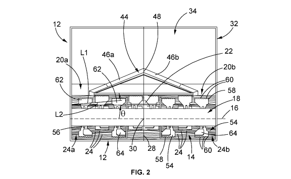
Figure 2 is a schematic representation of a section of the barrel and system
taken
through a plane which includes a central axis of the barrel;
Figure 3 is a schematic see-through representation of a portion of the barrel
and
system including a part of the distributor, the barrel and an impact mechanism
incorporated in the system;
Figure 4 is a schematic representation of the portion of the barrel and system
shown
in Figure 3;
Figure 5 is a schematic see-through representation of the portion of the
barrel
system shown in Figure 3 but from an opposite direction;
Figure 6 is a partial cutaway view of the barrel of the system;
zo Figure 7 is a representation of a housing of the system;
Figure 8 is a transverse section view of the system;
Figure 9 illustrates a possible relationship between embodiments of the
disclosed
system and spinners for spreading the discharge of the system when mounted on
a
combine harvester;
Figure 10 is a schematic representation of a possible configuration of an
impact
surface of a second embodiment of the disclosed barrel when the impact surface
is
laid flat;
Figure 11 is a view of section AA of Figure 10;
Figure 12 is an enlarged view of a portion of the impact surface shown in
Figure 10;
CA 03158137 2022-04-14
WO 2021/077180 PCT/AU2020/051154
Figure 13 is a photographic representation of a constructed prototype of the
disclosed system with a barrel having an impact surface as represented in
Figures
10-12;
5
Figure 14 is a schematic representation of a third embodiment of a barrel that
may
be incorporated in a hammer system;
Figure 15 is a section view of the barrel shown in Figure 14;
Figure 16 is a schematic representation of the barrel shown in Figure 14 but
from an
opposite angle;
Figure 17 is a representation of a section of a segment that may be used to
construct
the barrel depicted in Figures 14-16;
Figure 18 is an end view of an embodiment of the barrel shown in Figures 14-
16;
Figure 19 is a schematic representation of a possible arrangement of barrels
in a
zo fourth embodiment of the disclosed system;
Figure 20 is a schematic representation of a possible material processing
arrangement constructed from two systems each in accordance with a fifth
embodiment of the disclosed system;
Figures 21a and 21b are schematic representations of a first bypass mechanism
enabling the material to selectively either enter the system for processing or
bypass
the system that may be incorporated in various embodiments of the disclosed
system;
Figures 22a and 22b are schematic representations of a second bypass mechanism
enabling the material to selectively either enter the system for processing or
bypass
the system;
CA 03158137 2022-04-14
WO 2021/077180
PCT/AU2020/051154
16
Figure 23a is a photograph of a spreader on combine which has been modified by
the addition of plates and shown in a raised position to accommodate an
embodiment of the disclosed barrel and system;
Figure 23b is a photograph of spreader shown in Figure 23a from an alternate
angle
but also showing an embodiment of the system which, when the spreader is
lowered
to its operational position, is able to feed its discharge into the modified
spreader to
enhance the performance of the spreader;
Figures 24a-24d depict a sixth embodiment of the disclosed barrel which
comprises
a central portion and opposite end portions that are coupled together as well
as an
outlet control system which is operable to vary the total area of the outlet
of the
barrel. The outlet control system shown in different positions, progressively
opening
from a minimum outlet area position shown in Fig 24a to a maximum outlet area
position shown in Figure 24e;
Figure 25 is a perspective view of the embodiment of the barrel shown in
Figures
24a-24d;
zo Figures 26a-26c are perspective, side and top views respectively of the
end portion
of the embodiment of the disclosed barrel shown in Figures 24a-25;
Figure 27 is a perspective view of the embodiment of the disclosed barrel
shown in
Figures 24a-26c from an alternate angle and depicting the addition of an
outlet
deflector and a portion of a drive system for the impact mechanism within the
barrel;
and
Figures 28a is a schematic representation from one angle of an embodiment of
the
disclosed barrel shown in Figures 24a-27 integrated into a combine to form a
material processing system and including: a feed conduit which may be fitted
to the
combine to assist in directing the processed material and air flow from the
barrel into
combine spinners or other downstream processing equipment; and, a drive system
for driving the disclosed material processing system;
CA 03158137 2022-04-14
WO 2021/077180
PCT/AU2020/051154
17
Figure 28b is a front view of the system shown in Fig 28a with material flow
directed
out of the page toward an observer;
Figure 28c is a perspective view from an alternate angle of the disclosed
system
shown in Fig 28a;
Figure 28d is a side view of the disclosed system; shown in Fig 28a
Figure 28e shows a variation of the system of Figures 28a-28d in which a
rubber or
pliant cover is located over a feed distributor of the system;
Figure 29 is a schematic perspective view of an embodiment of the disclosed
system
incorporating a tailboard lying in a generally horizontal plane and having
adjustable
fins orientated to provide a divergent spread of material and air from the
outlet of the
associated barrel;
Figure 30 is a side view of the embodiment shown in Figure 29;
Figure 31 is a schematic perspective view of an embodiment of the disclosed
system
zo as shown in Figure 29 but with the fins of the tailboard reconfigured to
provide a
convergent flow of material and air from the outlet of the associated barrel;
Figure 32 is a perspective view of an embodiment of the disclosed system and
showing how material flow is integrated into downstream equipment, in this
instance
spinners, of a combine. This Figure also shows the tailboard inclined upwardly
from
the horizontal plane to enable the system to feed material to downstream
equipment
from below;
Figure 33 is a perspective view of an embodiment of the disclosed system with
an
associated tailboard declined from horizontal plane to feed material and air
from
above to combine downstream equipment again this instance is in the form of
spinners;
CA 03158137 2022-04-14
WO 2021/077180 PCT/AU2020/051154
18
Figure 34 is a side view of the disclosed system and associated sideboard
shown in
Figure 33 but without the spinners;
Figure 35 is a schematic representation of the disclosed system integrated
into a
combine having vertically disposed downstream processing equipment (in this
instance spinners) and where the associated tailboard with fins is arranged to
provide a diverging flow of material to the vertical spinners;
Figure 36 is a schematic representation of the disclosed system as per Figure
35
except that the tailboard fins are configured to provide a convergent flow of
material
to a region between the spinners;
Figure 37 is a photograph of a baffle installed in a combine at the end of a
grain pan
that may be used in conjunction with embodiments of the disclosed system to
assist
in throwing straw beyond, and therefore reduce the risk of it entering, the
system;
Figure 38 is a photograph of a guide or deflect a plate installed at one side
of a top
sieve of a combine which may be incorporated to assist in directing chaff
inwardly as
it falls below onto a distributor incorporated in an embodiment of the
disclosed
zo system.
DETAILED DESCRIPTION OF SPECIFIC EMBODIMENTS
The following description of the embodiments of the disclosed material
processing
system 10 (hereinafter also referred to as "system 10) and associated barrel
12 are
made in the context of an agricultural application where the system 10 is
mounted on
a combine harvester for processing chaff and in particular devitalising seeds
(for
example, but not limited to weed seeds) in chaffs. For a crop harvested by a
combine harvester the chaff may typically comprise a combination of small
portions
of straw, target grain husks and seeds from weeds or volunteers.
With reference to the accompanying drawings an embodiment of the disclosed
system 10 comprises a material processing barrel like structure or body 12
(also
referred to hereinafter more simply as "barrel 12") having a milling or impact
surface
14 and a central axis 16. The impact surface 14 is impervious, in that
material cannot
CA 03158137 2022-04-14
WO 2021/077180
PCT/AU2020/051154
19
pass through the surface 14, but rather is contained by the surface. An impact
mechanism 18 is located within barrel and is capable of rotating about the
central
axis 16. In a broadest and most general embodiment the system 10 has at least
two
openings, one forming an inlet and the other forming an outlet. The openings
are
spaced along the axis 16. As explained in more detail later, material
processed by
the system 10 is caused to travel in a spiral path along the axis 16 when
flowing from
an inlet to an outlet. The openings, be they inlets or outlets may be at axial
ends of
the barrel 12 or, as shown in the present embodiment, formed in the
circumferential
surface of the barrel 12.
Various mechanisms may be used either separately or in any combination of two
or
more to induce the spiral flow path of the material (and air in which the
material is
entrained) from an inlet to an outlet. These mechanisms can include:
= protrusions 24 such as ribs or rasp bars that are incorporated in the
impact
surface 14;
= vanes or fins which are supported on and extend radially inward from the
impact surface 14;
= longitudinal grooves or ribs that follow a twisted path; or by the
attachment of
vanes or fins; on a shaft 52 of the impact mechanism 18;
zo = the configuration and/or angle of hammers 54 incorporated in the
impact
mechanism 18.
In the embodiment illustrated in Figures 1-9 the system 10 has openings 20a
and
20b formed in the barrel 12 (i.e. in the surface 14) at axially spaced
locations along
the axis 16. In this example the openings 20a and 20b are at opposite axial
ends of
the barrel 12. In this, but not all embodiments, the openings act as or form
inlets and
are hereinafter referred to in general as "inlet(s) 20". At least one further
opening 22
is formed in the barrel 12 at a location intermediate of the inlets 20 (i.e.
between the
opposite axial ends of the barrel 12). In this embodiment the opening 22 is an
outlet
and is hereinafter referred as "outlet 22".
In this embodiment the impact surface is an impervious impact surface 14. This
surface is a textured surface. The texturing can take many forms such as a
plurality
CA 03158137 2022-04-14
WO 2021/077180
PCT/AU2020/051154
of surface reliefs such as surface valleys, pits or grooves and/or surface
elevations
such as ridges, ribs, bumps, protrusions and projections; or other
irregularities. In
this embodiment and as seen most clearly from Figures 3-6 the texturing of the
impact surface 14 comprises a plurality alternating protrusions or ridges 24
and
5 valleys 26. The alternating arrangement is in the circumferential
direction of the
barrel 12, i.e. about the central axis 16.
In this embodiment the protrusions 24 are in the form of ribs, hereinafter
referred to
as "ribs 24". With reference to Figure 2 the ribs 24 are arranged in two sets
of ribs
10 24a and 24b. The ribs 24 in the first set 24a extend from or near the
first inlet 20a
toward a mid transverse plane 28 of the barrel 12 that passes through a
midpoint 30
of, and lies transverse to the central axis 16. The ribs 24 in the second set
of ribs
24b extend from or near the second inlet 20b toward the mid plane 28. In this,
but
not all embodiments, the ribs 24 lie in an oblique orientation with reference
to the
15 central axis 16. The sets of ribs 24a and 24b are symmetrical in terms
of their
orientation about the mid plane 28.
In a general sense, the protrusions 24 flow path (a) is inclined or oblique
relative to
the central axis 16 or (b) otherwise follows a spiral like path about the axis
16.
zo However, in this specific embodiment and as shown in Fig 2 each of the
ribs 24
extends in a continuous straight line L1 from its respective inlet 20 to the
mid plane
28. In this embodiment the ribs 24 (i.e. line L1) run at an included angle 8
with
reference to an axial line L2 on the impact surface 14 of about 5 -15 .
However, in
other embodiments the ribs 24 may be made to run at a different angle to
change the
residence time of material within the system 10. The varying of the angle of
the ribs
24 can be manual by way of a swap out of the surfaces in the barrel; or by
having
ribs 24 that are movably coupled to enable their angle to the axis 16 to be
varied by
actuators (e.g. linear actuators). The actuators may be controlled from the
combine
cab. Optimal processing by automatically adjusting actuators control system
and
machine learning may be implemented. This may be mechanically simple for later
described embodiments of the barrel and system in which the barrel is composed
of
a plurality of separate segments 70.
CA 03158137 2022-04-14
WO 2021/077180
PCT/AU2020/051154
21
The system 10 has a housing 32 which includes the barrel 12. Perhaps as best
seen
in Figure 7 the housing 32 has an inlet chute 34. The inlet chute 34 is formed
between opposite side walls 36 and 38, and opposite top and bottom walls 40
and
42 of the housing 32. Within the inlet chute 34 there is a distributor 44 for
feeding
material entering the inlet chute 34 to each of the inlets 20. The distributor
44 feeds
substantially equal amounts of material to each of the inlets 20a and 20b,
assuming
a uniform feed across the inlet chute 34. This is achieved by forming the
distributor
44 with respective slide or ramp surfaces 46a and 46b (hereinafter referred to
in
general as "slide surfaces 46") which are declined from a common ridge 48 that
is
io aligned with the mid p1ane28 and midpoint 30.
The outlet 22 is formed as a cut out or removed portion of the barrel 12. The
outlet
22 is symmetrical about the mid plane 28. The circumferential extent of the
outlet 22
may range between about 30 and about 90 . One or more louvers or gates 50 may
be provided in the outlet 22. The louvers 50 may be located in or across the
outlet 22
and are operable to vary or control the open area of the outlet 22.
Specifically, the
louvres 50 may be swung between a fully open position where they extend in
respective radial planes with reference to the axis 16, to a fully closed
position where
the louvres 50 lie substantially tangentially to a radius from the central
axis 16.
zo Varying the position of the louvres 50 has the effect of varying the
outlet area of the
outlet 22. This in turn can be used as one mechanism to vary residence time of
the
material in the system 10.
The outlet 22 can be located anywhere about the outer circumference of the
barrel
12. The location of the outlet 22 may be determined by the nature of the
machine to
which the system 10 is fitted including the relative position of the system 10
and a
downstream system or mechanism to which the output of the system 10 is fed,
for
example a chaff spreader, tail board, or a straw chopper. For example, if it
is desired
to feed the output of the system 10 to a straw chopper from a location where
the inlet
of the straw chopper is about level with the bottom of a horizontally
orientated
system 10, then the outlet 22 may be formed to extend across a 60 arc from
say
about the 4 o'clock to the 6 o'clock position around the rotation axis 16. In
another
example where say a horizontally installed system 10 is required to feed its
output to
a chaff spreader or a straw chopper with an inlet located vertically above the
axis 18
CA 03158137 2022-04-14
WO 2021/077180
PCT/AU2020/051154
22
then the outlet 22 may be formed to extend across about 600 from about the 12
o'clock position to the 2 o'clock position. The louvres 50 and/or cowlings 23
(described later) may also be used to assist in directing the output of the
system 10
is required.
The impact mechanism 18 comprises a central shaft 52 and a plurality of
hammers
54 that are coupled to and extended generally radially of the central shaft
52. The
shaft 52 may also be arranged to induce an axial motion of the material and
air
flowing through the barrel 12. This may be achieved for example by profiling
the
outer circumferential surface of the shaft 52 for example: with longitudinal
grooves or
ribs that follow a twisted path; or by the attachment of blades or fins which
are
profiled to induce material and air flow in a desired direction for example
from the
inlets to the outlet.
Each hammer 54 has an arm 56 that may be pivotally or otherwise flexibly
coupled
to the shaft 52. In this way the hammers act as flails. In the event of such
coupling
the hammers 54 are able to swing, deflect or otherwise provide a degree of
give in a
radial plane if impacted by a hard foreign object within the mill. The purpose
of this is
to help reduce the risk of major damage to the hammers 54 and the system 10.
Each hammer 54 has a radially outer edge 58 located with a small clearance
from
the impact/milling surface 14. The edge 58 is formed with a plurality of
spaced apart
grooves or flutes 60. The purpose of the flutes 60 is to assist in fragmenting
elongated material such as straw that may enter system 10 from the inlets 20
and
reducing smearing of material on the impact surface 14. Additionally, the
flutes 60
may have a combing effect on straw contained in the chaff and thus further
assist in
creating a differential in motion and/or processing of the straw in comparison
to weed
seeds contained in the chaff. In this embodiment an impact side 62 of the
hammers
54 is substantially planar and lies in an axial plane. A trailing face 64 of
the hammers
is scalloped. The purpose of this is to balance the impact mechanism 18. In
the
absence of the scalloping the centre of gravity of the hammers 54 would be
offset
from the centre of gravity of the shaft 52 which may lead to instability
together with
increased bearing wear and heat generation.
CA 03158137 2022-04-14
WO 2021/077180
PCT/AU2020/051154
23
The hammers 54 are distributed about the shaft 52 both circumferentially and
axially.
Thus at least two of the hammers are axially displaced relative to each other
along
the shaft. Many different distribution patterns for the hammers 54 are
possible. For
example, the hammers may be arranged in rings having the same number of
hammers 54 (for example 6 hammers in each ring) where the hammers in each ring
are evenly spaced circumferentially about the shaft 52 and the hammers in
axially
adjacent rings are axially aligned with each other. However, in another
embodiment
the hammers can be arranged in rings as in the previous example but where the
hammers in axially adjacent rings are circumferentially offset from each
other. In yet
a further alternative the hammers may be arranged in a spiral path from one
end of
the shaft 52 to the other.
In yet a further variation the hammers 54 may be rigidly fixed to the central
hub
rather than pivotally coupled. Also, the hammers may be formed to have a
single
arm rather than the illustrated bifurcated arm; and/or have simple planar
faces on
opposite sides. The radially outer axial edge of the hammers can also be
formed with
a simple straight edge rather than with the flutes 60.
The general operation of the system 10 is as follows. The system 10 may be
zo conveniently mounted on a combine harvester near an end of a grain
sieve, with the
axis 16 orientated horizontally. The function of the grain sieve is to
separate a target
grain from chaff. The target grain may fall into a sump and then be moved for
example with an auger to a storage bin. The remaining chaff progresses toward
the
end of the sieve from which it feeds into the inlet chute 34 of the disclosed
system
1 0. (In the absence of the, or another, mill the chaff from the grain sieve
would
ordinarily feed into a chaff spreader.)
Some of the chaff near the inside of the side walls 36 and 38 may fall
directly into the
inlets 20a, 20b. The remaining chaff falls onto the distributor 44 which then
feeds
that chaff to the inlets 20a and 20b of the barrel 12. The chaff in the barrel
is
processed by way of being impacted by the hammers 54 and accelerated toward
and onto the impact surface 14. The material impacted by the hammers and
accelerated onto the impact surface 14 is fragmented. Weed seeds contained
within
the chaff are also fragmented and devitalised.
CA 03158137 2022-04-14
WO 2021/077180
PCT/AU2020/051154
24
The material entering the barrel 12 from the inlets 20 may be transported
toward the
outlet 22 by one or both of two actions of the system 10. One of these is a
pressure
differential created by the rotation of the hammers 54 about the axis 16. This
rotation
increases air pressure within the barrel with reference to ambient pressure.
Provided
the outlet 22 is open to at least some extent the outlet 22 forms a low-
pressure area
within the barrel 12. Accordingly, the system 10 generates an air flow from
the inlets
20 to the central outlet 22 which entrains the material being milled. A second
of
these actions arises by configuring the impact surface 14 to guide, or
otherwise
induce motion of, the material entering through an inlet 20 to travel in a
spiral path
about the axis 16 toward an outlet 22. In this embodiment this is achieved by
way of
the configuration of the protrusions/ribs 24. The angling of the ribs 24 with
reference
to the axis 16 together with the rotation of the hammers 54 creates a screw
like or
auger effect assisting to move the material in a spiral flow path about the
axis 16
toward the outlet 22.
As indicated above different embodiments of the system 10 can be provided with
ribs
24 with different angles of inclination 8 to adjust residence time within the
system 10
and thus vary the degree of fragmentation and particle size reduction. In
terms of the
zo spiral flow path, changing the angle 8 changes the induced axial
component of the
material velocity so that the spiral path between an inlet and an outlet can
be
changed. For example, increasing the angle 8 increases the induced axial
component to reduce the inlet to outlet distance and therefore decrease
residence
time. This may also be looked at from the perspective of the effective contact
area of
the material with the impact surface increasing hence the increased processing
i.e.
fragmentation/devitalisation of the weed seeds.
The angles of inclination 8 can be actively varied by way of actuators
controlled for a
cab of a combine. This requires that the ribs 24 are coupled with the body of
the
barrel 12 so that they can move in unison to vary the angle 8. This has the
effect of
changing the pitch of the spiral path about the axis 16 of the material and
air.
CA 03158137 2022-04-14
WO 2021/077180
PCT/AU2020/051154
The material discharged from the outlet 22 may be fed into two of spinners 66
(see
Fig 9) that rotate on respective vertical axes 68 that lie the same distance
from the
rotation axis 16 and on opposite sides of the outlet 22. The spinners 66
rotate in
opposite directions to each other so that material discharged from the outlet
22
5 between the rotation axes 68 is carried further away from the outlet 22.
The
discharge from the outlet may alternately be directed into another device such
as a
straw chopper. In another application the discharge may be used to assist in
spreading other material such as for straw spreading on a combine by directing
the
discharge onto a straw tailboard or into a straw spreader. In each of these
alternate
io applications the airflow generated by the system 10 is used to augment
to
functionality of the device to, or into, which it is directed.
Figures 23a and 23b illustrate the integration of an embodiment of the system
10
with a spreader 100 on a CASE IHTM combine harvester. In Figure 23a the
spreader
15 100 as shown in a raised position. Figure 23b also shows the spreader
100 in a
raised position but from the side of the combine with the outlets 22 of the
system 10
installed on the combine being visible. Here the spreader 100 has been
modified by
the installation of blanking plates 102 that span from opposite sides of the
spreader
toward its central region, and integral flanges 104. The flanges 104 are
formed with
zo arcuate edges 106 of a radius substantially the same as the outer radius
of the barrel
12 and spread apart to locate about the outlets 22. When the spreader 100 is
thus
swung down into its operational position indicated by the arrow 108 the
discharge
from the outlets 22 is feed between the flanges 104 into the spreader 100. The
inclusion of the blanking plates 102 with their integral flanges 104 assists
in creating
25 more wind/airflow and turbocharges the effect of the spreader 100.
The system 10 can be embodied in many different ways and may be subject to
numerous modifications and variations without departing from the broad
underlying
structure and method of operation. For example, the barrel 12 may be
fabricated by
texturing a planar metallic surface and then rolling the surface into a barrel
shape
having a single seem that can be joined. In such construction an expandable or
otherwise resilient axial joint can be formed so that the barrel 12 is
provided with a
degree of give and allow it to flex in a radial or circumferential direction.
This may
CA 03158137 2022-04-14
WO 2021/077180
PCT/AU2020/051154
26
assist for example to pass a hard foreign object. This effect can be enhanced
if the
barrel is formed from two or more sectors which together when joined about a
common axis form the barrel with expandable or resilient joints between each
of the
sectors.
One way of forming an expandable or resilient joint is to construct the barrel
12 from
say two generally hemi-cylindrical parts, they can be coupled together to form
a
substantially cylindrical barrel like structure. Each of the parts may extend
for a little
more than 1800 so that there is a degree of overlap. For example, each extends
for
185 so that there is a 5 of overlap along opposite axial edges of the parts.
The
parts can be coupled together by a spring mechanism such as a pneumatic spring
or
a mechanical spring which will allow the parts to move radially away from each
other
against the bias of the spring.
In another variation of the system 10, the protrusions 24 of the impact
surface 14
need not be in the form of straight ribs that extend the full length from an
axial end of
the barrel 12 to the mid plane 28. Rather the protrusions may be in the form
of much
shorter ribs which are spaced apart and arranged in a line from an end of the
barrel
12 to the mid plane 28. In another example impact surface 14 may be textured
with
zo different surface effects that may include raised bumps, domes, plateaus
or a
plurality of valleys or recesses formed in an otherwise smooth circumferential
surface as shown in Figs 1 0-1 3 as impact surface 14t. In yet another
variation the
protrusions 24 may be in the form of rasp bars coupled to the inner surface of
the
barrel 12. The rasp bars could have base which is flat or planar base, or
alternately
have a base that has a generally convex or triangular profile.
Figures 1 0-1 3 show the impact/milling surface 14t in a laid flat condition
while Figure
13 is a photographic presentation of a working porotype of the disclosed
barrel
system 10t with its barrel 12t formed with the textured impact surface 14t.
The
impact surface 14t in general terms is a surface having a plurality of surface
reliefs
such as surface valleys, pits or grooves and/or surface elevations such as
ridges,
ribs, bumps, protrusions and projections; or other irregularities. In this
embodiment
the impact surface 14t comprises a plurality of the valleys 128. At least some
of the
valleys 128 have two orthogonal axes 130 and 132 of unequal length. A shorter
of
CA 03158137 2022-04-14
WO 2021/077180
PCT/AU2020/051154
27
the orthogonal axes 130 extend in a circumferential direction with respect to
the
rotation axis 16. A longer of the orthogonal axes 132 extends parallel to the
rotation
axis 16. Yet in other embodiments the axis 132 can be oblique to the axis of
rotation
16. Having the axes 130 and 132 of unequal length provides the valleys 128
with a
generally elliptical shape.
Between the valleys 128, the surface 14t as a plurality of lands 134 that are
"flat"
with respect to the axis of rotation 16 so that every point on the lands 134
lie on
respective land radii of the same length. That is, if the surface 14t were
laid out flat
as indeed shown in Figures 10-12 all the lands 134 are flat and lay on a
common
plane. Also, the valleys 128 have edges 137 that lie on respective edge radii
of the
same length from the rotation axis. Thus, in this configuration the edges 137
all lie on
the radii of the same length as those of the lands 134.
The valleys 128 are arranged in a generally uniform pattern of stacked
circumferential rows R1, R2, R3, and R4. In rows R1-R3 the valleys 128 have
respective axes 132 of the same length. However, in row R4 the valleys are of
the
shape of a hemi-ellipse and have a shorter axis 132. The number of rows of
valleys
on the surface 124 can vary. The ends of the valleys 128 in one row may, as
they do
zo in this embodiment, lie between the ends of adjacent valleys in an
adjacent row.
When the impact surface 14t is used in relation to chaff it is believed that
it may
induce a differential flow of material depending on the material type in the
chaff (for
example short pieces of straw compared with weed seed) leading to different
residence time within the mill. Without wishing to be bound by theory it is
believed
that straw pieces may flow along the lands 134 and across the edges 137 of the
valleys 128, while weed seeds in the chaff may predominantly impact in the
valleys
128. Consequently, it is believed that the seeds would travel more slowly and
therefore have higher residence time within the impact sector than the straw
pieces.
Fig 13 show an example of a system 10t constructed with the barrel 12t having
a
milling surface 14t as describe in relation to Figures 10-12. The system 10t
is also
marked with the impact mechanism 18, hammers 54, valleys 128 and lands 134.
CA 03158137 2022-04-14
WO 2021/077180
PCT/AU2020/051154
28
Figures 14-18 depict further embodiments of the system 10 with an alternate
barrel
12a and show a possible method of construction.
The substantive difference between the barrel 12 of Fig 1-9, and the barre112a
in
Figs 14-18 is that in the embodiment shown in Figures 14-18 (and indeed the
barrel
12t shown in Figure 13) the barrel 12a is composed of a plurality of
circumferential
segments 70a-70j (hereinafter referred to in general as "segments 70") capable
of
being demountably coupled together along the common central axis 16. Each
segment 70 has a corresponding circumferential wall 72a-72j (hereinafter
referred to
in general as "circumferential wall 72") with an inner impervious impact
surface 14s.
When the segments 70 are coupled together along the axis 16 the individual
inner
impervious impact surface 14s of each segment 70 together form the impervious
impact surface 14 of the barrel 12a. Also, the circumferential walls 72 of
each of at
least two of the segments is provided with openings 20 to form at least one
inlet 20
and at least one outlet 22 spaced along the central axis.
In the embodiment shown in Figures 15 and 16 each of the segments 70 has the
same axial length. The segments 70a and 70b are adjacent each other at one end
of
the barrel 12a while the segments 70i and 70j are adjacent each other and at
an
zo .. opposite end of the barrel 12a. The respective circumferential wall 72
of segments
70a, 70b, 70i and 70j are formed with openings which, in this embodiment, form
inlets 20 to the barrel 12a. Thus, openings (in this instance acting as
inlets) are
formed at each of the opposite axial ends of the barrel 12a.
The segments are 70e and 70f are located between the opposite axial ends of
the
barrel 12a. The respective circumferential walls 72e and 72f of these segments
are
formed with openings which act as outlets 22. The outlets are formed with
respective
fixed cowlings 23 instead of or in addition to the louvers 50 to assist in
directing the
processed material to a spinner or other device such as a chopper (not shown).
The
segments 70 may be formed as short cylinders or rings, and the openings, when
provided, may be formed as a cut out or removed section of the cylinder or
ring.
Alternately the circumferential walls 72 can be made from separate sections 73
(see
Fig 17) for example each extending for a fraction of 360 and which, when
coupled
CA 03158137 2022-04-14
WO 2021/077180
PCT/AU2020/051154
29
together about a common axis form a full 360 ring. In Figure 17 the section
73
extends for 1800. But in other embodiments this section 73 may extend for
other
angular portions such as 90 . It is also possible for a circumferential wall
72 to be
composed of several sections 73 of different circumferential extent, for
example one
section of 180 and two additional sections of 90 ; or, three sections of 90
and two
sections of 45 . If a segment 70 is required with an opening having a
circumferential
extent of 90 and the corresponding circumferential wall 72 for the segments
70 may
be formed of a 180 section and a 90 section only, leaving a 90 opening.
Each section 73 may have an associate supporting frame 75. The frame 75 may
have radially extending curved flange portions 77 and axially extending
flanges 79
extending between the flanges 77. The flanges 79 of two or more sections 73
(depending on their angular extend, e.g. 45 , or 60 , or 90 , or 180 ) are
connected
together to form a segment 70. The flanges 77 of adjacent segments 70 are
coupled
together to form the barrel 12a.
In one variation flexible or resilient joints may be made between (a) each of
the
section 73 in a segment 70 and/or (b) adjacent segments 70 in the barrel 12.
For
example a rubber mount can be located between the flanges 79 of the section 73
zo making up a segment 70. Additionally, or alternately with amounts may be
located
between the flanges 77 of adjacent segments 70. The provision of the flexible
or
resilient joints provides the barrel 12 with a degree of flexibility in the
axial and/or
radial directions which may assist in the passing of a blockage or otherwise
minimising the likelihood of damage due to the entrainment of a hard foreign
object
in the material being processed.
The circumferential wall 73 in one embodiment may be fixed to the frame 75.
However, in an alternate embodiment the circumferential wall 73 may be
demountable supported or movably supported within the frame 75. When
demountable supported the circumferential wall 73 can be removed to thereby
form
an opening in the corresponding barrel 12a. When movably supported, the
circumferential wall 73 can be for example pivoted between a closed position
where
it follows the curvature of the corresponding frame 75, as shown in Figure 13;
and an
CA 03158137 2022-04-14
WO 2021/077180
PCT/AU2020/051154
opened position where it remains supported by the frame 75 but displaced from
axial
alignment with the frame 75.
To provide a segment 70 with an opening (either as an inlet or on outlet) one
or more
5 of the sections may be simply removed or omitted. The circumferential
extent of the
openings, be they inlets or outlets, may be fixed or variable. The ability to
vary the
circumferential extent of an opening can be achieved for example by the use of
movable doors (for example sliding the pivoting) as explained in greater
detail later in
this specification. In one example for a system 10 and barrel 12 with fixed or
static
10 openings, the circumferential extent may range, but is not limited to,
from about 45
to about 180 .
The segments 70c. 70d, 70g and 70h (see Fig 16) have respective
circumferential
walls which have no openings and so their corresponding inner impervious
impact
15 surfaces 14s extend for a full 360 . For those segments 70 having
openings, the
corresponding impervious impact surface 14s extends for 360 minus the
circumferential extent of the opening.
The texturing of the individual impervious impact surface 14s, and thus the
overall
zo composite impact surface 14 of the barrel 12a may be in any of the forms
described
above in relation to the first embodiment of the barrel 12.
Although not shown in the drawings, in this embodiment louvres, the same or
similar
to those described above in relation to the first embodiment, may be located
in or
25 across the outlets 22 and operable for varying an effect open area of
the outlets.
The present embodiment lends itself to the incorporation of an aperture
mechanism
74 (see Figures 14, 16 and 18) located between two mutually adjacent segments
70.
Conveniently the aperture mechanism 74 may be coupled between the frame 75 of
30 mutually adjacent segments 70. The aperture mechanism 74 enables control
of a
flow of material between the mutually adjacent segments. The aperture
mechanism
74 provides another way to control the residence time of the material within
the mill
by varying the flow area between adjacent segments. In the absence of the
aperture
mechanism 74 the flow area between adjacent segments is in effect -rrr2 where
"r" is
CA 03158137 2022-04-14
WO 2021/077180
PCT/AU2020/051154
31
the inside radius of the segments 70. This flow area can be decreased by use
of the
aperture mechanism 74.
In the illustrated embodiments the aperture mechanism 74 is in the form of a
set of
one or more plates 76 having inner edges 78 that can be moved radially
inwardly
and outwardly to vary the effective flow area between adjacent segments 70.
Figure
18 shows a segment 70 with a radius "r" and an aperture mechanism 74
comprising
two opposed plates 76 coupled with the segment 70. The plates 76 have been
moved in a radial inward direction so that their inner edges 78 lie on a
radius r1 <r,
thereby reducing the flow area from a maximum of Trr2, when the aperture
mechanism 74 is retracted so that the edges 78 lie on the radius r, to a
smaller flow
area.
The position of the aperture mechanism 74 can be varied by removing mechanical
couplings between adjacent segments 70, moving the aperture mechanism 74 to
produce the desired flow area, and then reinstalling the mechanical couplings.
In a different embodiment aperture mechanism 74 may be provided as one of a
set
of a plurality of interchangeable aperture mechanisms wherein at least two
aperture
zo mechanisms have a central opening of different area. For example, the
aperture
mechanism 74 in a set may each comprise an annular plate with a different
inner
diameter. In an alternate arrangement the aperture mechanism 74 may comprise a
plurality of plates that slide or rotate relative to each other, for example
similar to an
aperture of a camera. In this way once the aperture mechanism 74 has been
installed in the barrel 12a the size flow area can be changed by operation of
an
actuator and associated mechanisms such as a lever, cam or gears. When
installed
on a combine harvester for the purposes of milling chaff, this variation of
flow area
may be adjusted by a driver operating an in-cab control. Irrespective of its
physical
form the aperture mechanism 74 enables control of the residence time and thus
the
degree of processing of the material.
Additionally, or alternately to the aperture mechanism 74, this and other
embodiments of the disclosed system 10 and barrel 12 can be provided with
internal
vanes or fins that extend radially inward from the impact surface 14. The
vanes are
CA 03158137 2022-04-14
WO 2021/077180 PCT/AU2020/051154
32
used to increasing or decreasing the pitch length of the spiral flow path, in
a manner
similar to that described above in relation to the ribs 24. To be able to do
this the
vanes or ribs are coupled with the barrel 12 in a manner so that their angle
relative to
the axis 16 can be varied. For example, linear actuators located on the
outside the
barrel 12 can be connected to the barrel to the vanes or fins. The actuators
can be
controlled by a combine operator from the combine cab.
If desired mesh screens can be provided across the openings, be they inlets 20
or
outlets 22. Although it is envisaged that most likely if screens are provided
that are
installed across the outlets 22. For the outlets 22, the screen could be used
in
conjunction with or as an alternative to the louvers 50.
The impact mechanism 18 for the barrel 12a (and 12t) shown in Figures 14-18
(and
Fig 13) may be of the same form as that described in relation to the first
embodiment
shown in Figures 1-9.
In each of the disclosed embodiments the inlets 20 and the outlets 22 are
rotationally
offset from each other about the rotation axis 16. Therefore, a piece of
material
entering through an inlet 20 (or its corresponding fragments following impact
with the
zo impact mechanism 18 and/or against the impact surface 14) must travel in
a path
about the rotation axis to reach an outlet 22. Moreover, when the inlets 20
and
outlets 22 are offset from each other along the rotation axis 16, the material
(or its
fragments) must travel in a spiral like path to move from an inlet to an
outlet. This
path may comprise more than one complete revolution about the axis 16.
Although it
should be understood that due to the configuration of the system 10 the
material
being processed is directed to flow in a spiral path irrespective of whether
or not the
inlet 20 and the outlet 22 are rotationally offset.
The number of revolutions may be controlled by any one, or any combination of
2 or
more of:
= the form or configuration of the texturing on the impact surface 14, as
described above in relation to the first embodiment;
CA 03158137 2022-04-14
WO 2021/077180
PCT/AU2020/051154
33
= by the operation of the apertures 74 increasing the residence time of the
material within the barrel 12a;
= the axial distance between inlets and outlets along with the axis 16 of
the
barrel 12a;
= the angle of inclination 8 of the ribs 24; and
= the angle of inclination/pitch of vanes or fins that extend radially
inward from
the impact surface 14.
The above described ways of controlling the number of revolutions is
applicable to all
embodiments of the disclosed system 10 and barrel 12.
A mill incorporating the barrel 12a shown in Figures 14-18 may include an
impact
mechanism 18 rotatably supported within the barrel 12a, housing 32 and
distributor
44 as described above and shown in Figures 1-9.
Also, in the illustrated embodiments the hammers 54 are depicted with
generally
planar surfaces 62 and 64 that extend in a radial direction to their axial
edge 58.
However, the impact side 62 may be curved. Moreover, the impact side 62 can be
curved in different directions depending on the axial location of the hammers,
and in
particular their axial distance relative to the inlets 20 and the outlet 22.
For example,
zo the impact side 62 can be curved or hooked in a forward direction with
reference to
the direction of rotation about the axis 16 near the inlets 20 to assist in
scooping
material and air into the barrel 12. However, near the outlet 22 and the mid
plane 28
the impact side 62 may be: planar as in the illustrated embodiment; or, curved
or
hooked in a rearward direction with reference to the direction of rotation
about the
axis 16 to increase radial exit velocity. Indeed, in a more general sense, the
system
10 may incorporate different hammers 54 along the axis therebetween. These
differences may be in terms of one or more the length, shape, and
configuration of
the hammers. Also, in this and every other embodiment of the disclosed system
10
and barrel 12 the distance between the edge 58 of the hammers 54 and the
impact
surface can be varied. This variation may be controllable by way of a control
system
that can be operated by a driver from a cabin of a combine fitted with the
disclosed
system 10.
CA 03158137 2022-04-14
WO 2021/077180
PCT/AU2020/051154
34
The shape, configuration and/or orientation of the hammers also influences air
flow
and may be designed to generate a specific effect on air flow, and thus
material flow,
through the system 10. The shaping may include curving of the hammers 58 as
described in the above paragraph. Alternately the hammers may be orientated so
that they remain planar but lie in planes that are oblique relative to the
radius of the
mill. The hammers 58 may be oriented in the oblique planes symmetrically about
opposite sides of the central radial plane 28. In yet a further variation the
hammers
may be twisted or angled for example like a fan blade or provided with an
aerodynamic profile like a propeller to generate an airflow in a specific
direction for
example from an inlet 20 to an outlet 22.
In a further variation the distributor 44 may be coupled to or otherwise
operatively
associated with a pivoting or self-levelling cleaning shoe of a combine to
provide an
even distribution of feed to the inlet chute 34 and thus the inlets 20 when a
combine
is traversing an incline or unlevel ground. This is shown for example in
Figures 28a-
28e where a distributor 44 is coupled to a cleaning shoe 29 of a barrel 12v
(described in greater detail later). In some embodiments the distributor 44
can
reciprocate backward and forward in a horizontal plane. In addition, because
of the
coupling of the distributor 44 to the cleaning shoe, the vibration of the
cleaning shoe
zo is also imparted to the distributor 44.
In the illustrated embodiments of the barrel 12, 12t, and 12a the distribution
of
openings forming inlets and outlets are arranged symmetrically about the mid
plane
28. But as explained later this is not an essential requirement and may vary
depending on the combine to which the mill is mounted and relative locations
of the
sieve of the combine and the inlet of the mechanism to which the output the of
the
system 10 is fed. Also, while in the illustrated embodiments openings acting
as inlets
are provided at the axial ends of the barrel 12, 12a, with outlets provided
between
the axial ends; this can be reversed so that milled material exits from one
axial end
or both opposite axial ends.
As may be appreciated by those skilled in the art the basic function of
embodiments
of the disclosed barrel allow material to pass through without tight control
on size.
The amount of seed damage/devitalisation is controlled by the angle of wrap
about
CA 03158137 2022-04-14
WO 2021/077180 PCT/AU2020/051154
the axis 16 and number of rotations about the axis 16, speed of rotation of
the impact
mechanism and the configuration of the impact surface 14. As previously
discussed
the surface has the ability to separate and damage seeds while providing no or
less
damage to straw; or otherwise provided a differential flow, and/or processing,
of
5 weed seeds and straw.
In yet a further variation shown in Figure 19 a plurality of barrels 12x, 12y
may be
provided side-by-side, with their respective axes 16 parallel to each other
and
arranged so that the discharge from one barrel 12x feeds directly into the
inlet of the
io adjacent barrel 12y. In this embodiment each of the barrels 12x, 12y has
an inlet 20
and an outlet 22 that extends for the substantially the full length of that
barrel 12x,y;
but are circumferentially spaced by 180 from each other. Thus, material
entering the
inlet 20 of the barrel 12x will travel through about 180 to the outlet 22,
where it
would then flow into the inlet 20 of the adjacent barrel 12y and travels
through a
15 further 180 before reaching the outlet 22 of that barrel. Thus, in
effect the material
would have passed through a full revolution about the axis 16 of any one
barrel,
being milled between the impact mechanism and the impervious impact surface
14.
A potential benefit of a mill incorporating 2 (or more) barrels 12 side-by-
side in the
manner shown in Figure 19 is increased throughput.
Figure 20 depicts a barrel system 10d having two barrels 12d arranged side by
side.
Each barrel 12d receives approximately one half each of the total chaff stream
and
feed the milled chaff to a pair of side-by-side chaff spreaders (not shown).
The
system 10d has an inlet 20 one axial end and an outlet 22 at an opposite axial
end.
Moreover, the system inlet 20 comprises separate inlets 20d one in each of the
barrels 12d. Likewise the system outlets 22 comprises separate outlets 22d one
in
each of the barrels 12d. Thus, in contrast to the earlier illustrated
embodiments the
barrel system 10d to not have inlets 20 at opposite axial ends. Because of
this each
system 10d does not need and is not provided with a distributor 44.
Nevertheless, a
distributor 44 or an equivalent structure for feeding substantially equal
amounts of
the chaff stream to each of the inlets 20 may be provided.
The barrels 12d are mounted side-by-side with their respective axes 16
parallel to
each other and their respective inlets 20 and respective outlets 22 being
radially
CA 03158137 2022-04-14
WO 2021/077180
PCT/AU2020/051154
36
adjacent to each other. This provides parallel processing of the chaff stream.
In a
conceptual sense the system 10d may be considered to be the functional
equivalent
of the system 10 shown in Figures 15 and 16 cut in half in the mid plane 28
between
the two outlets 22 and folded back on itself so that the two halves lie
parallel to each
other with their inlets 22 mutually adjacent and their inlets 20 mutually
adjacent. In
this embodiment of the mills 10d may be mounted in a north-south orientation
rather
than the east west orientation shown in Figs 1, 2, 9 and 13-19.
In a variation to the embodiment shown in Figure 20 the inlets 20d can be
formed at
the axial end of the respective barrels 12v, rather than in the
circumferential surface
of the barrels 12v. Doing this may simplify the feed arrangement and input
flow of
material into the barrels 12v because for example chaff can be fed directly in
to the
barrels 12v in the axial direction so that the chaff feed from the sieve does
not need
to change direction to enter the barrels 12v. This may however necessitate a
moving
of the bearings for the respective shafts in the barrels 12v.
Alternately the inlets 20d may be kept in the circumferential wall of the
barrels 12v,
and the outlets 22d moved from the circumferential wall to the adjacent axial
end.
Indeed, as suggested earlier in this specification, both the inlets 20d and
the outlets
zo 22d can be located at the axial opposite ends of the respective barrels
12v. In each
one of the above variations for the inlet and outlet location, the material
being
processed travels in a spiral path between axially spaced apart inlets and
outlets.
When an axial end is not used as an inlet or an outlet, is closed by a plate
or other
structure for example as shown in Figs 2, 7, 9, 16, 20, 22a, 22b, and 27-28b.
Figures 24a -28d depict yet another alternate configuration and construction
of the
barrel, designated as 12v and associated system 10v. The barrel 12v has a
central
section 120 and opposite end sections 122. The sections 120 and 122 are
coupled
together and co-centric with the central axis 16. In this embodiment each of
the
sections 122 is provided with inlet openings 20 enabling material to be fed
into the
barrel 12v. The sections 122 are tapered, increasing in their outer diameter
in the
axial direction toward the centre or mid transverse plane 28 of the barrel
12v. The
tapered sections 122 are configured so, at their axial inner most end 124,
their
interior surface has the same inner diameter as that of the central section
120.
CA 03158137 2022-04-14
WO 2021/077180 PCT/AU2020/051154
37
Optionally the tapered section has a cut off plate 139 which may be angled to
the
direction of the flow. Plate139 slows the circumferential velocity and adds an
axial
velocity component to stop material traveling around and around and move the
material toward the centre of the machine.
In yet a further variation (not illustrated) applicable to this and all other
embodiments
of the disclosed barrel, rather than only a length of the barrel commensurate
with the
inlets being tapered, the taper may extend to the central plane 28 of the
barrel, or
indeed for the full length of the barrel. The latter may be applicable for
example in
embodiments where the barrel has an inlet at one end and an outlet at an
opposite
end for example similar to that shown in Figure 20. The inclusion of such a
taper can
assist in the flow of material and air because it creates a reduction in
pressure from a
small diameter end to a large diameter end of the taper.
As most clearly seen in Figure 24d the central section 120 has an outlet 22
that
extends for, in substance its whole length. The central section 120 is
constructed
from a plurality of individual segments 70a - 70f (hereinafter referred to in
general as
"segments 70") which are coupled together side-by-side along the central axis
16.
The outlet 22v is comprised of individual outlets 22 in each of the segments
70.
The barrel 12v includes an outlet control system 126 which is operable to vary
the
distance between an inlet 20 and the outlet 22v and so the path length and
residence time of material flowing through the barrel 12v. The outlet control
system
126 varies the axial distance between the inlets 20 and outlet 22v.. In this
embodiment the outlet control system 126 comprises two gates 129 that are
slidably
supported on the barrel 12v and can be moved in an axial direction toward and
away
from each other. (Although in other embodiments the same effect can be
achieved
by providing a plurality of gates that together can cover the entirety of the
outlet 22
and can be individually moved by: way of a pivoting or swinging action; or,
sliding in
a circumferential direction, i.e. about the axis 16 direction.) Each gate 129
has a
circumferential width at least equal to the circumferential width of the
outlet 22v (and
therefore also each of individual outlets 22). Actuators (not shown) may be
controlled
from a cabin of a combine to which the barrel 12v and system 10v is fitted to
control
CA 03158137 2022-04-14
WO 2021/077180
PCT/AU2020/051154
38
the position of the gates 129 and therefore the distance from an inlet 20 to
the outlet
22v.
In this embodiment the outlet control system 126 enables the distance between
an
inlet 20 to the outlet 22v to be varied between a minimum in which the gates
129 are
at their respective axial outer most positions and uncover the entirety of the
outlet
22v, shown in Fig 24d; to a maximum where each gate 129 is moved in the axial
inward direction (i.e. toward each other) and each covers about one third of
the
outlet 22v, shown in Fig 24a. When the control system 126 is in the
configurations
io shown in Figure 24d, providing the minimum distance between an inlet 20
and the
outlet 22v, the system 10v and barrel 12v provide minimal material processing
and in
effect act as a chaff spreader. This may also be considered as being a
"bypass"
configuration of the system 10v and barrel 12v.
By operating the outlet control system 126 to vary the distance between an
inlet 20
and the outlet 22v the path length and thus number of rotations of material
about the
axis 16 can be varied from the minimum shown in Figure 24d to the maximum
shown
in Figure 24a. Commensurate with this the percentage of seed devitalisation
increases, as does power consumption. When the distance is at the minimum then
zo .. the barrel 12v and corresponding system 10v in essence act as a blower
generating
an air flow than entrains the weed seeds. This additional air flow may be feed
into
downstream equipment such as a spinner or spreader, or straw chopper or a
tailboard that spreads the material by directing the material as shown in
Figures 29-
36.
Figures 26a-26c show one of the end sections 122 of the barrel 12v in more
detail.
The inlet 20 of the section 122 comprises a hopper 130 and a partial frusto-
conical
portion 132. The partial frusto-conical portion 132 has an opening into which
the
hopper 130 is fitted. This opening extends for the axial length of the portion
132. The
hopper 130 has at least a first sloping wall 134a that assists in directing
feed material
for the barrel 12v toward the central axis 16. In this embodiment the hopper
130 also
has a second sloping wall 134b that also slopes to assists in directing feed
material
for the barrel 12v toward the central axis 16 and is perpendicular to the wall
134a.
Indeed, the hopper 130 may be provided with additional sloping walls 134c and
CA 03158137 2022-04-14
WO 2021/077180
PCT/AU2020/051154
39
134d, which together with the walls 134a and 134b define the mouth 136 of the
hopper 130 forming an inwardly sloping surface around the entire inner
circumference of the mouth 136. The inside of the inlet 20 there is a tapered
cut off
guide 139 that forces material in an axially inboard direction. The guide may
be fixed
to the wall 134a. Looking at Figs 26a and 26c, assuming the shaft 52 is
rotating in
the clockwise direction at least some of the material being induced to flow by
air and
mechanical act action of the hammers, when striking the guide 139 from below
is
forced axially inwardly which in Fig 26c is to the left-hand side.
Optionally, hammers 54a or other feeding arms/mechanisms (hereinafter referred
to
in generally as "hammers 54a") may be attached to portion of the shaft 52 that
extend through each section 122. The hammers 54a act primarily to assist in
directing the feed material from the hopper 130 through the inside of the end
sections 122 into the central portion 120. The assistance afforded by the
hammers
54a is by a combination of physical impact and imparting of momentum to the
weed
seeds, and also generating an air flow in the axial in a direction, i.e.
toward the
middle of the shaft 52, or central portion 120. Due to the tapered nature of
the end
portions 122 the hammers 54a extend for a shorter length in the radial
direction to
the hammers 54 in the central portion 120.
With reference to Figure 27 an outlet deflector 138 may be coupled to an
outside of
the barrel 12v and arranged to direct the discharged processed material from
the
barrel 12v in a particular direction. In the embodiment shown in this Figure
the
deflector 138 extends for a length of two thirds of the length of the outlet
22v. More
particularly the deflector 38 extends for a portion of the outlet 22v formed
between
the segments are 70b and 70e inclusive. An actuator (not shown) may also be
provided that can be controlled from a cabin of a combine to vary the angle of
the
deflector 138. The outlet deflector 138 can of course be used with other
embodiments of the barrel 12 described in the specification.
Each of the barrel is depicted in the embodiments described in relation to
Figures 1-
27 have either the whole of their length (Figures 1-23) or substantial portion
of their
length between opposite inlets (Figures 24a-Figure 27) with a constant inner
diameter. However, in a further possible variation of these embodiments, these
CA 03158137 2022-04-14
WO 2021/077180
PCT/AU2020/051154
lengths may be conical in nature so that their inner diameter varies along the
length
of the axis 16. The purpose of this is to induce or enhance the flow of
material and
air through the barrel and in particular from the inlets to the outlets.
5 Figures 28a-28e depict how an embodiment of the system 10v and
corresponding
barrel 12v may be integrated into a combine. These Figures depict mechanisms
and
systems enabling the embodiment of the system 10v to work with and in a
typical
combine with minimal to no interference or detrimental effect to the operation
of the
combine. In these Figures for the purposes of visual simplification the barrel
12v is
10 shown as a simple cylinder.
Figures 28a - 28d show how the system 10v acts to integrate material flow
throughout the combine. Material, for example chaff containing weed seeds,
from a
cleaning shoe 29 of a combine is fed to the distributor 44. The distributor 44
directs
15 the chaff laterally to the inlets 20 at the axial opposite ends of the
barrel 12v. The
distributor 44 reciprocates backward and forward in a horizontal plane; and,
is
vibrated by its connection to the cleaning shoe 29. This motion acts to
prevent or at
least minimise the risk of the chaff sticking or building up on the surfaces
of the
distributor 44, which may otherwise cause blockage or an uneven distribution
of
zo material to the opposed inlets 20.
Figure 28e shows a further variation where the distributor 44 is static or
otherwise
fixed relative to the barrel 12 but is provided with a rubber or other pliant
material
cover 145 that lays over the surface of the distributor 44 and is caused to
move or
25 vibrate relative to the distributor 44. This can be achieved for example
by coupling
the cover 145 to: the top sieve; or a pulley 147 of the drive system 150 for
the
system 10 by an eccentrically coupled arm 149.
The material after being processed in the system 10v and barrel 12v is
discharged
30 through the outlets and onto the deflector 138. The deflector 138
deflects the
discharge material into a feed duct 140. The feed duct 140 may be coupled to a
structure, or other equipment of the combine. Nevertheless, the feed duct 140
is a
part in the overall material flow integration provided by this and other
embodiments
of the disclosed barrel and associated system. In this embodiment the feed
duct 140
CA 03158137 2022-04-14
WO 2021/077180
PCT/AU2020/051154
41
is in the general form of a rectangular tube with a funnel like inlet 142. A
discharge
splitter 144 splits the material flow through the duct 140 into two separate
and
diverging streams. These streams may be fed to other processing equipment
which
are part of the combine such as a set of spinners which act to throw the
receive
material onto the ground across the width of a header of the combine. The
general
flow of the material /chaff is depicted in these Figures by the phantom arrows
F. In
this way the duct 140 acts as a link or conduit in the flow path of the
processed
material helping to constrain and guide the material and air flow to spinners
or other
downstream system/equipment with minimal diffusion or loss. The material
streams
may also provide additional material and air energy (velocity and pressure) to
improve the spread of the system. Optionally the ducting can be fully sealed.
Figures 28a-28d also illustrate one possible drive system 150 for transferring
drive
from an engine/PTO of the combine to the shaft 52 of the system 10v. A belt
(not
shown) is used to transfer torque from the engine/PTO to an OEM pulley 152
(which
is not a part of the drive system 150). As seen in Figure 28b, without the
drive
system 150, the drive belt could engage to a pulley 156 coupled to the shaft
52 in a
plane 154 (represented by the dashed line) if the shaft 52 were extended to
the left
hand side to reach the plane 154. But instead, the drive system 150 is
configured to
zo displace the plane inwardly toward a centre of the combine to a coupling
plane 158
in alignment with the pulley 156 shown in Figure 28b. The effect of this on a
combine
may be substantial in relation to its turning circle and overall
manoeuvrability. This is
because an embodiment of the system 10 is likely to be fitted in the same
region or
area of the combine as the steering axle and associated wheels. By configuring
the
drive system 150 to displace the coupling plane 158 in an inward direction
toward a
central the combine, interference with the turning circle and steering of the
combine
can be eliminated or at least minimised.
The drive system 150 includes an idler pulley/jack shaft 160 which is coupled
to the
pulley 156 by way of a belt 162. The pulley 160 rotates about an axis that is
parallel
to the shaft 52. A tensioner 164 may be interposed between the pulleys 156 and
160
to adjust tension in the belt 162. The pulley 160 is provided with multiple
grooves (for
example 6-8 grooves) and extends from one end coplanar the pulley 156 on the
shaft 52 toward the plane 154. Moreover, the pulley 160 is formed with an
axial
CA 03158137 2022-04-14
WO 2021/077180
PCT/AU2020/051154
42
length so that one of its grooves lies in the same plane as a transfer pulley
166. The
transfer pulley 166 is coupled to the same shaft as the OEM pulley 152. A belt
168 is
coupled between the pulleys 166 and 160. A tensioner pulley 170 may be
disposed
between the pulleys 166 and 160 to adjust the tension in the belt 168.
As shown in Figures 29-36 embodiments of the system 10 may be integrated with
combines having various configurations of spinners or straw choppers, for
feeding
material: directly into a spinner or chopper and from above or below; or,
directly onto
the ground. This integration may incorporate the use of tail boards with fins
in
various positions, for example to give a divergent spread, or alternately a
convergent
centre spread. Depending on the configuration of the combine into which the
system
10 is integrated the relative positions of the one or both inlets 20 and
outlets 22 may
be shifted in the circumferential direction about the central axis 16.
Figures 29 and 30 illustrate an embodiment of the system 10v which
incorporates a
tailboard 172 instead of the deflector 138 of Figures 28a-28d. The tailboard
172 is
has a plurality of fins 174 that guide material flow and air flow existing the
outlet 22.
The position of the fins 174 can be adjusted by fixing one end of the fins in
a
respective one of a plurality of holes 176, and the opposite end at a position
along a
zo slot 178. In Figure 29 the fins 174 are arranged to provide a divergent
flow of
material and air. Additionally, the tailboard is slightly inclined to project
the material
and air in an upward direction.
The tailboard 172 is pivotally coupled, by pivot pins 180 (only one visible)
on
opposite sides and at an end closest the barrel 12v, to respective curved
brackets
182. Adjustment arms 184 are also pivotally coupled at one end to respective
sides
of the tailboard 172 and at another end in one of a plurality of holes formed
on the
curved brackets 182. This coupling arrangement of the tailboard 172 enables
the
inclination of the tailboard 172 to be adjusted. This can be done manually or,
remotely by the use of actuators (not shown) that may be controlled from a
cabin of
the combine.
Figure 31 shows a variation of the arrangement of Figures 29 and 30 where the
tailboard 172 is again generally horizontal but the disposition of the fins
174 has
CA 03158137 2022-04-14
WO 2021/077180
PCT/AU2020/051154
43
been changed so that they direct the material and air from the outlet 22 in a
convergent rather than diverging manner. This configuration of fins 174 is
useful
when the material is being fed to downstream equipment such as a spinner or
chopper.
Figures 32 illustrates an embodiment of the system 10v with a tailboard 172
inclined
upwardly from the horizontal to feed a set of spinners 66 from below. The fins
174
are arranged to provide a convergent flow of material and air through an
optional
intervening feed duct 140.
Figure 33 illustrates an embodiment the system 10v which is located above a
set of
spinners 66. Material from the outlet 22 converges due to the orientation of
the fins
174 and is directed down the tailboard 172 into the spinner 66. So here the
tailboard
172 is inclined below the horizontal to feed material and air into the
spinners 66. In
this embodiment there is no intervening feed duct 140 as in the previous
embodiments. However, this duct 140 can be included if considered necessary or
desirable for example to maintain pressurisation. Figure 34 shows the system
10v of
Figure 33 (but without the spinners) from the side highlighting the declined
angle of
the tailboard 172 to facilitate the feeding of material from above to the
spinners.
Figures 35 and 36 illustrate the juxtaposition of embodiments of the disclosed
system 10v in relation to vertically orientated spinners 66. The difference
between
the two embodiments is in the configuration of the fins 174 on their
respective
tailboards 172. In Figure 35 the fins 174 are configured to produce a
divergent flow
of material to the spinners 66. Here the spinners rotate to throw material
outwardly,
i.e. towards opposite sides of an associated combine. In Figure 36 the fins
174 are
configured to produce a convergent flow of material to a region between the
two
spinners 66.
The arrangements shown in Figures 29-36 not exhaustive of the different ways
in
which embodiments of the disclosed system 10 and barrel 12 may be incorporated
in
a combine. The system and barrel may be installed and arranged to feed its
processed material and generated air flow to other downstream equipment such
as a
chopper. Either by use of a tailboard angled in a particular manner and
variations in
CA 03158137 2022-04-14
WO 2021/077180
PCT/AU2020/051154
44
the configuration of the fins; or, by otherwise orientating the barrel 12 and
outlets 22,
the outlet material can be directed to flow for example: (a) directly into a
chopper by
passing a spinner; (b) directly into the spinner; or (c) directly onto the
ground; and
the spinners 66 may be orientated in any plane form horizontal to vertical and
from
above or below the barrel 12. The flow of material from the outlet can be
pressure
fed using a sealed duct or conduit for example similar to the feed duct 140
described
above. The duct 140 in some embodiments may be coupled directly to barrel 12
or a
part of the system 10 and thus become part of the system 10 itself.
Figure 37 shows other modifications that may be made to a combine to enhance
the
integration, and/or performance of all embodiments of the disclosed system.
The
modifications may include but are not limited to:
a) The addition of an upstream splitter 300 on a top sieve 302 (only the
forward
most edge of which is shown in this drawing) of a combine in which the
system/barrel is fitted. The splitter 300 acts to divide and spread a flow of
chaff
falling from the top sieve onto the distributor 44.
b) The addition of inwardly directed guide plates 304 on opposite sides of
the top
sieve 302 to direct chaff more centrally on to the underlying distributor 44.
The
guide plates 304 may be incorporated instead of or in conjunction with the
splitter 300. In Figure 37 the flow of chaff from the top sieve toward the
system
10 is depicted by the phantom arrows F. This Figure attempts to show that the
flow of the chaff travelling along a central region of the sieve 302 is
diverted as
it approaches the trailing edge of the sieve 302 by the splitter 300 toward
the
left or right on to the underlying distributor 44, while chaff travelling
along the
left-hand or right-hand edges of the top sieve 302 is diverted inwardly by the
guide plates 304 onto the underlying distributor 44.
c) A baffle 306 may be installed across the barrel 12v and distributor 44
downstream of its inlets 20. The baffle 306 may include a rubber or other
pliant
material curtain. The baffle 306 maybe coupled to a lifting mechanism to
enable
it to move in a vertical plane up or down to enable the air flow of the
cleaning
CA 03158137 2022-04-14
WO 2021/077180
PCT/AU2020/051154
shoe to be balanced with the barrel. Baffle 306 is structured to allow air to
pass
over while not impacting air flow.
In addition to the above, integration of embodiments of the system 10 into a
combine
5 may also be improved by the installation of an extension plate or baffle
310 (see Fig
38) at an end of a grain pan. The baffle 310 extends past the normal throw of
an
over-head beater. The installation of the baffle 310 may reduce the likelihood
of
straw entering the system 10. Figure 38 shows an example of a baffle 310
inclined
from the horizontal and extending from an end of the grain pan of a combine.
The system 10 may be installed or mounted in a combine using a powered or
manual mechanism that enables the system 10 to slide (for example vertically)
or to
be folded/swung between a use position where the system 10 is active to
devitalise
weed seeds and integrate into the overall material flow through the combine;
and a
maintenance or access configuration where either the system 10 or other parts
of the
combine can be more easily accessed.
Embodiments of the system 10 may be installed so that the central axis 16 is
orientated vertically rather than horizontally. Such embodiments may then
utilise the
zo action of gravity to also provide a level of control of residence time
within an
associate barrel 12.
Also, all embodiments of the system 10 may be coupled by way of pivot or
articulated joints to a frame or other structural member of a combine and
provided
with actuators to enable the system 10 to be moved between various positions.
This
can subsequently be used to enable easy access for maintenance to various
parts of
the system 10 or the combine, and also to assist in directing the discharge
from the
outlets 22 to achieve different effects, for example discharging directly onto
the
ground, discharging into a straw chopper or a chaff spreader, or discharging
onto a
tail board.
The system 10 may be mechanically coupled to a power take off of a combine
harvester, for example by way of pulleys and belts, or driveshafts, gearboxes
and
universal joints. Alternately the system 10 may be driven by a hydraulic motor
CA 03158137 2022-04-14
WO 2021/077180
PCT/AU2020/051154
46
plumbed into a combine is hydraulic system (assuming of course it has one) or
an
electric motor.
Embodiments of the disclosed barrel 12 and system 10 lend themselves to many
further structural and operational modifications as well as facilitate the
incorporation
of various sensors to enable monitoring of the performance of the system 10 as
well
as a harvester on which it is mounted. Information obtained from the sensors
may
also be used to automatically modify the mill or harvester performance. Some
of
these are briefly discussed below.
= A gate or trapdoor may be provided on the inlet chute 34 or the
distributor 44
that can be opened and closed by an actuator controlled from a cabin of the
harvester for capturing a downstream sample of chaff prior to flowing into an
inlet 20. Alternately automatic sampling may be incorporated. Capturing a
sample of the chaff enables monitoring or measurement of grain loss in the
separating system of the combine. Figure 4 shows examples of two alternate
locations for a trapdoor 80 can be selectively opened and closed to obtain a
sample of the chaff. Such a trapdoor could lead to: a small receptacle for
holding a sample for later testing; or alternately, feed the sample to an on-
board measurement system that may make real time measurements of grain
loss against samples collected at an upstream end of an associated
shaft/straw separation system (e.g. a thresher). The measurement system
may include an optical or vision-based system for comparing upstream and
downstream samples. Information obtained from such measurements may be
used for automatically adjusting header parameters of the combine via a
control system that may also include artificial intelligence processing. Also,
as
described later information obtained from the measurement of the sample is
derived from the trapdoor 80 may be used for weed mapping.
= Rather than providing a trapdoor 80 in the inlet chute 34 or the
distributor 44
samples may also be obtained by forming a segment 70 at an inlet 20 with a
section 73 of its wall 72 that can be selectively pivoted between a sampling
and a processing or operational position. In the processing position the
CA 03158137 2022-04-14
WO 2021/077180
PCT/AU2020/051154
47
section 73 forms part of a circumferential impact surface of the barrel 12. In
the sampling position the section 73 is pivoted or swung away from a
remaining portion of the wall 72 creating an opening through which some of
the chaff entering the inlet 20 is diverted to a sample collection receptacle,
or
a measurement system. While the chaff sample taken at this location may be
subject to a small degree of processing (i.e. milling) is believed that the
degree of processing/milling would be sufficiently small as to not render the
percentage of grains in the chaff unmeasurable.
lo = A sample of the processed/milled material could also be taken at
the outlet 22
and compared with the above-mentioned sample taken at the downstream
end either by the trapdoors 80 or an inlet 20. These samples may be
compared to give a measurement of the degree of processing/milling and in
particular weed seed devitalisation provided by the system 10. In turn this
can
be compared to a prescribed target and communicated to an in-cabin
monitoring and control system, or an autonomous control system. In either
case the control system may be arranged to effect a change in the
configuration or operational characteristics of the system 10 to achieve a
target degree of processing/weed seed devitalisation. For example, the
control system may be arranged to vary one, or a combination of any two or
more of:
o the speed of rotation of the impact mechanism 18;
o torque delivered to the impact mechanism 18
o position of the louvres 50;
o position or degree of opening of the apertures 74;
o travel speed of the combine.
= Power measurement sensors may also be incorporated in the system 10 to
give a measure of power (i.e. torque) loss across the system 10. This in turn
gives an indication of the degree of material processing/milling provided by
the system 10. The control system mentioned immediately above can use this
to control one or more of the operational characteristics or settings of the
mill
CA 03158137 2022-04-14
WO 2021/077180
PCT/AU2020/051154
48
or the combine. The power sensors may be in the form of inductive encoders
that measure the torque input and output of the system 10.
= In yet a further design variation the system 10 and in particular the
barrel 12
can be constructed to have a bypass feature in which the barrel 12 can be
opened along its entire length prior to the material traversing more than a
set
portion of a revolution about the axis 16. For example, with reference to
Figure 18 the barrel 12 may be constructed so that each segment 70 has a
wall section 73a with a pivot connection Pa at the 12 o'clock position and a
wall section 73b with a pivot connection Pb at the 6 o'clock position.
Actuators
(not shown) are provided to pivot the wall sections 73a,b from a closed
position shown in Figure 18, to an open or bypass position in which the
segments are pivoted away from each other about the respective pivot
connections to open the barrel 12 a long its entire axial length. As result
material entering the mills 10 will undergo minimal processing (for example
contacting the impact surface 14 for at most 90 about the axis 16), prior to
being discharged. In this way the system 10 in this bypass configuration acts
more as a chaff spreader than a mill. The bypass characteristics of the system
10 can be further enhanced by constructing the system 10 so that sections 73
of the segments 70 can be selectively opened on an opposite side to act as
additional inlets. The ultimate configuration being that the system 10 can
have
in effect an actuatable inlet and a bypass outlet/opening both of which extend
for the full axial length of the system 10 and are rotationally offset from
each
other by between 30 - 180 (or any sub range within this range).
= Embodiments of the barrel mill composed of a plurality of segments 70 can
be
further modified by the provision of dedicated "outlet segments" that may be
reconfigured on demand to any circumferential location and to any angular
extent of open. For example, with reference to Figure 15 the segments 70e
and 70f could be replaced with the "outlet segments". These segments may
be provided with walls 72 which include for example twelve individual wall
portions each pivotally mounted to the segment frame 75. Each wall portion
may extend for slightly more than 30 , for example about 35 each. This gives
CA 03158137 2022-04-14
WO 2021/077180
PCT/AU2020/051154
49
an overlap of about 5 per for each wall portion to fit for example a hinge or
pivot pin. Separately controllable actuators may be provided for each wall
portion. The actuators can be controlled to swing the wall portion between a
closed position where it forms part of an inner circumferential wall of the
barrel, and an opened position where it forms an outlet opening. So, if for
example the actuators of two or three of such a mutually adjacent wall
portions are activated to move them to the open position, then together the
corresponding segments would form an outlet of 60 or 90 . The location of
the outlet about the axis of rotation 16 can likewise be controlled by
operating
the appropriate actuators.
= The inlet chute 34 and /or the diverter 44 may be reconfigurable between
the
configurations as shown in Figs 1-5, 7 and 8 where they direct feed material
into the barrel 12 to a bypass configuration. In the bypass configuration
where
the material that would otherwise be fed to the barrel 12 bypasses the barrel
12/system 10 and is directed to flow to other processing or handling systems
such as a spreader, chopper or tailboard. In one example a roller door 82 may
be fitted across the inlet chute 34 for example as shown in Figures 21a and
21b. The roller door 82 can be moved between an opened position in which it
leaves the chute 34 fully open, to a fully closed position depicted in these
Figures, which closes the inlet chute 34 so the mill/barrel is bypassed, and
the
material is diverted: to an alternate processing device such as a spinner,
chopper or, tailboard; or, directly onto the ground.
= There are other ways of achieving the same bypassing effect as described
immediately above. For example, the distributor 44 may be reengineered as a
reconfigurable structure comprising a plurality of panels 84, 86, 88, 90, 92
and
94, together with foldable side panels 96, all of which are coupled together
to
move between a first configuration as shown in Figures 22a and 22b. In
Figure 22a the diverter panels 84, 86, 88, 90, 92 and 94 are shown in the
diverting configuration in which material is diverted to the inlets 20. The
foldable side panels 96 are upright allowing material to flow into the inlets
20.
In Figure 22b the diverter panels 84, 86, 88, 90, 92 and 94 have been folded
down to a ramp like configuration, and the side panels 96 have been folded
CA 03158137 2022-04-14
WO 2021/077180
PCT/AU2020/051154
down to cover the inlets 20. Now material that is directed to the system 10
bypasses the inlets 20 flowing over the folded down diverter panels 84-94 and
side panels 96.
5 = In addition to the above-mentioned torque sensors, other sensors
may be
provided to provide operational data and signals to a processor and/or a
communications system. The sensors may include:
1. one or more blockage sensors arranged detect blockage in or reduced
10 mass flow rate of material through the system 10;
2. one or more vibration sensors arranged to sense vibration arising from
rotation of the impact mechanism 18;
15 3. temperature sensors to the temperature of bearing associated with
the
impact mechanism 18;
4. one or more proximity sensors to provide or cause the
generation of an
alarm when a person is within a designated distance of the impact mechanism
20 when it is rotating. Such sensors may also be arranged to directly or
indirectly
activate a light and/or an audible signal generator to indicate or otherwise
show that the impact mechanism 18 is still rotating thereby alert the person
that machine is not safe to work on;
25 5. air pressure sensors at various locations along the barrel 12
These sensors may feed their output signals/data to a data processor
associated
with the system 10 or a combine or other agricultural machine incorporating
the
disclosed system 10. The communication system may also be provided with the
30 system 10 or a combine or other agricultural machine incorporating the
disclosed
system 10. The communications system or data processor may also include a GPS.
The provision of data processing and communication systems enables data,
signals
or information from any one or more of the sensors to be communicated via a
CA 03158137 2022-04-14
WO 2021/077180
PCT/AU2020/051154
51
communications network including but not limited to the Internet or the
Internet of
Things, to a remote location and/or the operator's cab of the combine. The
data,
signals or information from the sensors may be provided directly from the
sensors,
or, as processed data, signals or information subsequent to processing by the
data
processor, or both.
Communicating the data, signals or information enables remote monitoring of
the
performance of the mill 10 as well as the combine harvester. The remote
monitoring
can for example enable manual or automated communication to a combine operator
or a service department of performance characteristics of the system 10 and/or
the
combine harvester. The performance characteristics may include: information
regarding wear of various components, the need for maintenance, or the
provision in
real time of alerts or alarms to the combine operator of potentially dangerous
performance characteristics such as bearing temperature.
The data, signals or information may also be used, together with other
operational
information communicated via the communication system such as forward speed of
the combine harvester and GPS data, to calculate the amount of material
processed
by the system 40/ associated combine harvester including geographically
tagging the
zo data. Other possibilities include weed mapping with the volume or
density of weeds
obtained either through the sampling of the material processed by the mill
using
samples for example obtained through the trapdoors 80, or by optical detection
of
weeds via detectors on the combine immediately prior to cropping and tagging
this to
corresponding GPS data. Biomass mapping is also possible for example by use of
.. the above described torque sensors. This may be beneficial in terms of
different
business or revenue models for commercialisation of the system 40 and/or
combine
harvester in enabling for example lease payments/charges being made on the
basis
of the calculated amount of material processed by the combine harvester.
The data, signals or information from the sensors and processed can be used in
real
time or otherwise to:
= to alert the combine harvester operator of various operational
characteristics
of the system 10 (to a component/sub-system level) and/or the harvester;
CA 03158137 2022-04-14
WO 2021/077180
PCT/AU2020/051154
52
= signal the need for maintenance and/or repair;
= determine performance characteristics of the system 10 and/or the combine
harvester;
= enable calculation of throughput of material processed by the system 10
and/or the combine harvester.
The data, signals and information communicated to the remote location may be
stored locally or on a cloud-based system. In any event the data, signals and
information may be fed to a machine learning/artificial intelligence system.
This in
turn may be arranged for example to: forecast expected lifespan of components,
system 10 throughput; and/or suggest potential adjustments to system or
combine
harvester parameters to improve operational efficiency.
The sensors may be operatively coupled to the data processor which can be
programmed to take one or more specific actions if a blockage or an anomalous
change in material flow is detected. These actions may include but are not
limited to:
operating a high-pressure air compressor to direct one of jets of air to a
location
where the change in material flow or blockage is detected; and /or reducing
the
ground speed of the system 10 or combine to reduce the volume of material
being
zo directed to the blockage site. In the latter case the data processor may
alert an
operator if and when that the blockage has cleared to enable a resumption of
normal
travel speed.
Embodiments of the disclosed system may also include actuators or structures
to
enable variation of configuration, position or interrelationship of component
parts to
facilitate control over aspects such as residence time of material within the
system
10. For example, the position and angle of the flails (axial component) may be
varied
manually prior to the operation or automatically through the use of actuators.
In
addition or alternately the following characteristics may be varied: the
degree of
aggressiveness/roughness of the impact surface 14 (e.g. the ribs 24 or the
shape
depth and configuration of the valleys 128 of the surface 14t, shown in
Figures 10-
12; which varies both of the degree of devitalisation but also the flow path
of material
CA 03158137 2022-04-14
WO 2021/077180 PCT/AU2020/051154
53
and thus residence time; the degree of opening or closing of the outlets 22
for
example using the control system 129 shown in Figures 24a-25.
Wear sensors may also be installed in and as part of the system 10 to provide
signals to an overall system control and monitoring system to provide an
indication of
the wear of the impact surface 14 of the barrel 12, or wear of the hammers 54.
For
example: a wear sensor that may be in the form of a plurality of conductors or
one or
more conductive meshes, may be impregnated in the impact surface 14 that break
to
change a measurable electrical characteristic such as current flow, resistance
or
.. capacitance when worn. Other examples include a load cell on a sacrificial
wear
plate; or ultrasonic thickness or surface roughness sensors. A proximity
sensor may
be incorporated to measure distance from the surface 14 to the flails/hammers
54 to
measure wear. The signals from the wear sensors may provide feedback via an
loT
system to enable global mapping of wear and continuous improvement.
In relation to the overall control of the system 10 the previously mentioned
torque
sensors may be provided to enable sensing of torque in the shaft 52 to enable
a
determination of power imparted to the material flowing through the system 10.
From
this control algorithms may be implemented to automatically adjust settings of
the
zo system 10 based on torque to optimise for seed kill, for engine power
available and
for optimum distribution of power available for destroying seeds, chopping
straw and
spreading both.
In the claims which follow, and in the preceding description, except where the
context requires otherwise due to express language or necessary implication,
the
word "comprise" and variations such as "comprises" or "comprising" are used in
an
inclusive sense, i.e. to specify the presence of the stated features but not
to preclude
the presence or addition of further features in various embodiments of the
system
and method as disclosed herein.