Note: Descriptions are shown in the official language in which they were submitted.
CA 03158313 2022-04-19
WO 2020/087032
PCT/US2019/058202
FLUIDIC DEVICES WITH REACTION WELLS AND CONSTRICTION CHANNELS AND USES THEREOF
RELATED APPLICATIONS
[001] This application claims the benefit of U.S. Ser. No. 62/751,266 filed on
October 26,2018, which
is incorporated by reference in its entirety.
FIELD OF THE DISCLOSURE
[002] This disclosure is generally related to the manipulation of fluids in a
microfluidics environment.
BACKGROUND OF THE DISCLOSURE
[003] Fluidic systems can be used to prepare particles, for example
microparticles or nanoparticles,
for use in a variety of applications such as, but not limited to, new
pharmaceutical therapeutic
formulations and medical diagnostic products. However, prior fluidic systems
for the manufacture of
particles, such as nanoparticles have many drawbacks such as inconsistent
results, inability to control
size, limited productivity, and costly scale-up. Furthermore, such systems
require experienced
specialists with long training periods and carry significant risk as personnel
running the manufacturing
process change. Thus, there is a need in the art for microfluidic devices that
can be used to produce
nanoparticles that are consistent in size and shape, and that have the ability
to control size and are
easy to use.
[004] Protein production is important in many areas of biotechnology. These
include the
development and testing of reagents for diagnostics assays and for the
production of protein biologics.
Such methods can include a protein precipitation step. However, methods for
precipitating proteins
can be difficult to perform consistently in large scale, require incubation
periods, and can damage
precipitated proteins, especially at high concentrations of precipitates.
Thus, there is a need in the art
for fluidic devices that can be used to precipitate proteins quickly,
consistently and that can be
effectively scaled up.
SUMMARY OF THE DISCLOSURE
[005] This disclosure provides fluidic devices that are useful in the
production of particles, such as
microparticles and nanoparticles, and protein precipitates. Furthermore, some
devices provided
herein are useful for the detection of precipitate reaction products.
[006] In some aspects, this disclosure provides a fluidic device that
comprises a first port; a first fluid
transport channel in direct fluid communication with the first port, a
reaction well; an overflow
1
CA 03158313 2022-04-19
WO 2020/087032
PCT/US2019/058202
channel; a second fluid transport channel in direct fluid communication with
the overflow channel; a
fluidic constriction channel in direct fluid communication with the reaction
well and the second fluid
transport channel; and, a second port in direct fluid communication with the
second fluid transport
channel (e.g., as illustrated in FIGS. 1, 2, and 10-14A) , or a fluidic device
assembly comprising at least
two of such microfluidic devices, or comprising other microfluidic devices
provided herein, including in
parallel or in serial. In illustrative embodiments, methods for using such
fluidic devices to produce
particles are provided.
[007] In another aspect, as illustrated in a non-limiting exemplary manner in
FIG. 15, provided herein
is a device sometimes referred to herein as a device for detecting a reaction
product, that comprises a
first port 1; a first fluid transport channel 1A, optionally having a
relatively straight or straight section
1A1 and an optionally rounded section 1A2; a reaction well 2; a fluidic
constriction channel 4; a passive
pressure sensing channel 3A; a second port 3; a second fluid transport channel
5A; a third fluid
transport channel 5A, an interface channel segment 5C and, a third port 6. In
one illustrative
embodiment, as illustrated in a non-limiting exemplary manner in FIG. 15, the
second fluid transport
channel 5A is in direct fluidic communication with the first fluid transport
channel 1A at an end of the
first fluid transport channel opposite the first port; the fluidic
constriction channel 4 is in direct fluidic
communication with the reaction well 2 and an interface channel segment 5C
directly connecting the
second fluid transport channel 5A and the third fluid transport channel 5B,
wherein the width of the
interface channel segment is typically identical to the width of the fluid
transport channel to which it
is directly connected; the reaction well 2 is in direct fluidic connection
with the passive pressure sensing
channel 3A at an end of the passive pressure sensing channel opposite the
second port 3; the passive
pressure sensing channel 3A extends from the reaction well 2 opposite the
fluidic constriction channel
4 and terminates at the passive pressure sensing channel port 3; and the first
fluid transport channel
1A is not in direct fluidic communication with the reaction well 2.
[008] In another aspect, provided herein, is a method for detecting a reaction
product, which in
illustrative embodiments uses a device for detection of a reaction product as
provided herein, as a
non-limiting example, the fluidic device discussed in the preceding paragraph.
[009] This Summary section is not intended to limit the scope or breadth of
the current disclosure.
Further details regarding aspects and embodiments of the present disclosure
are provided throughout
this patent application.
2
CA 03158313 2022-04-19
WO 2020/087032
PCT/US2019/058202
BRIEF DESCRIPTION OF THE DRAWINGS
[0010] The patent or application file contains at least one drawing executed
in color. Copies of this
patent or patent application publication with color drawing(s) will be
provided by the Office upon
request and payment of the necessary fee.
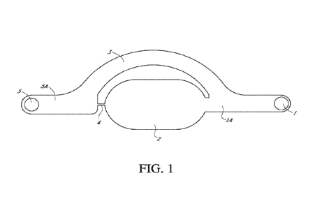
[0011] FIG. 1 illustrates an exemplary fluidic device that can be used to
produce nanoparticles. This
exemplary fluidic device is composed of a first port (part 1), first fluid
transport channel (part 1A),
reaction well (part 2), overflow channel (part 3), fluidic constriction
channel (part 4), second fluid
transport channel (part 5A), and second port (part 5).
[0012] FIGS. 2A-2C illustrates the introduction and removal of fluids from an
exemplary fluidic device
that can be used to produce nanoparticles. FIG. 2A. Step one: introduction of
first fluid into fluidic
device to fill reaction well 2 (solid coloring representing the first fluid
(e.g., organic solvent solution
comprising dissolved lipids or polymer solution); FIG. 2B. Step two: removal
of first fluid (e.g., organic
solvent solution comprising dissolved lipids or polymer solution); FIG. 2C:
Step three: introduction of
second fluid (e.g., aqeous buffer or water-soluble synthetic polymer solution)
into fluidic device to mix
with first solution thereby producing nanoparticles.
[0013] FIG. 3 provides the size distribution plot of five batches of liposomes
produced using an
exemplary fluidic device.
[0014] FIG. 4 provides transmission electron microscopy of liposomes produced
using an exemplary
fluidic device.
[0015] FIG. 5 provides results obtained using fluidic devices having fluidic
constriction channels of
different widths (relative to each device) and washing rates.
[0016] FIG. 6 shows the average number-weighted size of the lipid-based
micelles prepared using
DSPE-PEG dissolved in ethanol as the first fluid and PBS as the second fluid.
[0017] FIG. 7 shows the average number-weighted size of the polymeric micelles
prepared using PEG-
PLGA dissolved in ethanol as the first fluid and PBS as the second fluid.
[0018] FIG. 8 shows the average number-weighted size of the polymeric micelles
prepared using PEG-
PLGA dissolved in acetone as the first fluid and distilled water as the second
fluid.
[0019] FIG. 9 shows the average number-weighted size of the polymeric micelles
prepared using PEG-
PLGA dissolved in ethanol as the first fluid and PBS as the second fluid.
3
CA 03158313 2022-04-19
WO 2020/087032
PCT/US2019/058202
[0020] FIG. 10 illustrates an exemplary fluidic device including six pairs of
two pillars 7 distributed
within the reaction well 2 between the junction with the first fluid transport
channel 1A and the fluid
constriction channel 4 that can be used to produce nanoparticles.
[0021] FIG. 11 illustrates an exemplary fluidic device in which the shape of
the reaction well 2 was
changed by reducing the curvature of the well on one side to alter flow
patterns inside the reaction
well 2 that can be used to produce nanoparticles.
[0022] FIG. 12A illustrates an exemplary fluidic device in which multiple
fluidic device subunits are
connected in series, wherein the first fluid transport channel 1A of one
device in the series is
continuous with the second fluid transport channel 5A of the next device in
the series. FIG. 12B
illustrates an exemplary fluidic device in which multiple fluidic device
subunits are connected in series,
wherein the first fluid transport channel 1A of one device in the series is
continuous with the second
fluid transport channel 5A of the next device in the series, but wherein the
overflow channels 3 of each
subunit are on the opposite side of at least two, but optionally each,
successive fluidic device subunit.
[0023] FIG. 13 illustrates an exemplary fluidic device comprising multiple
fluidic device subunits
connected to one another by a common fluid transport channel 9 which is
connected to a common
port 10.
[0024] FIG. 14A illustrates an exemplary embodiment of a fluidic device
comprising multiple fluidic
device subunits with two inlet channels (12, 14) having associated separate
inlet ports (11 and 13,
respectively) that form a Y junction in fluid communication with the first
fluid transport channel 1A of
the first fluidic device in a series of fluidic devices. FIG. 14B provides the
number-weighted size
distribution for liposomes formulated using these first and second fluids in
the device of FIG. 14A.
[0025] FIGS. 15 and 15A illustrate an exemplary fluidic device in which 1 is a
first port; 1A is a first
fluid transport channel; 1A1 is a straight section of the first fluid
transport channel 1A; 1A2 is a rounded
section of the first fluid transport channel 1A; 2 is a reaction well; 4 is a
fluidic constriction channel; 3A
is passive pressure sensing channel; 3 is a second port; 5A is a second fluid
transport channel; 5B is a
third fluid transport channel; 5C is an interface channel segment; and 6 is a
third port.
[0026] FIGS. 16A-16C provide diagrams illustrating fluid flow while filling a
device according to FIG.
15. FIG. 16A shows initial introduction of a first fluid into the device
through the first port 1. FIG. 16B
shows further filling of the device, partially filling the reaction well 2 and
third fluid transport channel
5B. FIG. 16C shows complete filling of the reaction well 2 with first fluid
and partial filling of the third
fluid transport channel 5B.
4
CA 03158313 2022-04-19
WO 2020/087032
PCT/US2019/058202
[0027] FIGS. 17A-17C provide diagrams illustrating fluid flow when fluid is
withdrawn from a device
according to FIG. 15. FIG. 17A: The first fluid fills most of the device as
depicted in FIG. 16C. FIG. 17B:
A negative pressure is applied to the first port 1, causing the first fluid to
begin to recede from the
device towards the first port 1. The geometry and dimensions of the reaction
well 2, passive pressure
sensing channel 3A, fluidic constriction channel (not numbered here but the
part corresponding to 4
in FIG. 15) and fluid transport channels (5A, 5B, 5C, and 1A) prevents fluid
in the reaction well 2 from
leaving the device. FIG. 17C. Due to the design of the device, a small volume
of first fluid has been
captured in the reaction well 2. At this stage using this device embodiment,
essentially no other parts
of the device retain any fluid (i.e. the rest of the device is empty).
[0028] FIGS. 18A-18D provide diagrams illustrating steps in an embodiment for
using the device
according to FIG. 15. Top left panel FIG 18A: A second fluid (e.g. human
sweat) enters the device with
reaction well 2 filled with test solution from the third port 6 via positive
applied pressure, and enters
the third fluid transport channel 5B. Not illustrated as a separate figure,
fluid from the second fluid
reaches the reaction well 2, where it interacts with the captured first fluid.
Top right panel FIG 18B:
Fluid from the second fluid continues to flow through the device towards the
first port 1 where it exits
the device. FIGS. 18A and 18D depict precipitate development in the device
illustrated in FIG. 15. FIG
18C: As second fluid (e.g., sweat) mixes with first fluid (e.g. anti-
perspirant test compound) in the
opening of the reaction well at or near the interface channel segment 5C, a
precipitate begins to form.
FIG 18D: Precipitate PPT continues to grow the entire length of the second
fluid transport channel 5A.
as more second fluid flows into the device and interacts with first fluid.
Precipitate grows until it
eventually blocks the second fluid transport channel, inhibiting incoming
flow.
[0029] FIG. 19 shows a screenshot (still frame) from a video showing
precipitate formation ("PPT")
following the interaction of the first and second fluids. The device used to
produce the precipitate
shown in this figure included an optional thin channel 7 extending from the
passive pressure sensing
channel to the first fluid transport channel, not shown in FIG. 15. The width
of that channel was the
same width as the pressure sensing channel. Removing this optional thin
channel 7 had no signficant
effect on the functionality of the device.
[0030] FIG 20 illustrates a further exemplary embodiment of a fluidic device
comprising multiple
fluidic device subunits in series, with two inlet channels (12, 14) having
associated separate inlet ports
(11 and 13, respectively) that form a Y junction in fluid communication with
the first fluid transport
channel 201A of the first fluidic device in the series of fluidic devices. The
microfluidic device shown
in FIG. 20, as a non-limiting example, include 12 microfluidic device subunits
as 4 rows of 3 microfluidic
CA 03158313 2022-04-19
WO 2020/087032
PCT/US2019/058202
device subunits each, with each microfluidic device subunit connected in a
series. As demonstrated in
the Examples herein, the design in FIG. 20 was used to prepare a device with
small dimensions relative
to a device with larger dimensions (Table 1). The device with small dimensions
(Table 1) functions the
same as the design with large dimensions but is capable of forming smaller
nanoparticles due to its
reduced dimensions as provided in the Examples herein.
[0031] FIGS. 21A and 21B illustrate microfluidic flow (FIG. 21A) and mixing
(FIG. 21B) within an
exemplary microfluidic device similar in design to the microfluidic device of
FIG. 20. An increased
magnification view of one of the microfluidic devices is shown in the inset of
FIG. 21A. A representative
image of microparticles produced using such a device is shown in the inset of
FIG. 21B, with the bar
representing 1,000 nm.
[0032] FIGS. 22A and 22B provides data generated using the a microfluidic
device with the design
shown in FIG. 1. FIG. 22A is a graph showing the effective diameter and
polydispersity index (PDI) of
four batches (Formulation Number 1-4) of liposomes formulated in the device
and analyzed by DLS.
FIG. 22B is a graph showing the effective diameter/size and polydispersity
index (PDI) of liposomes
generated with identical input first liquid and second liquid, but different
flow rates.
[0033] FIGS. 23A to 23D provide data generated using the a microfluidic device
with the large
dimension embodiment of the design shown in FIG. 20. FIG. 23A is a graph
showing the effective
diameter and polydispersity index (PDI) of three batches (Formulation Number 1-
3) of liposomes that
were made using the device and analyzed by DLS. FIG. 23B is a graph showing
the effective diameter
and PDI of liposomes generated holding all parameters constant, but inputting
a first fluid and second
fluid at different flow rates. FIG. 23C is a graph showing the effective
diameter and PDI of liposomes
generated with identical input first fluid and second fluid, but different
flow rate ratios of an input
stream of the first fluid to an input stream of the second fluid. FIG. 23D is
a graph showing the effective
diameter and PDI of liposomes collected at different points during the process
of flowing 1L of
combined first fluid and second fluid through the fluidic device.
[0034] FIGS. 24A to 24C provide data generated using the a microfluidic device
with the small
dimension embodiment of the design shown in FIG. 20. FIG. 24A is a graph
showing the effective
diameter and polydispersity index (PDI) of four batches (Formulation Number 1-
4) of liposomes
formulated in the device and analyzed by DLS. FIG. 24B is a graph showing the
effective diameter and
PDI of liposomes generated with identical input first fluid and second fluid,
but different flow rates.
FIG. 24C is a graph showing the effective diameter and PDI of liposomes
generated with identical input
6
CA 03158313 2022-04-19
WO 2020/087032
PCT/US2019/058202
first fluid and second fluid, but different flow rate ratios of an input
stream of the first fluid to an input
stream of the second fluid.
[0035] FIG. 25 provides data generated using the a microfluidic device with
the large embodiment of
the design shown in FIG. 20 to precipitate proteins. Precipitate efficiency is
graphed for protein
precipitation experiments performed at different flow rate rations of BSA to
TCA.
[0036] FIG 26 illustrates a further exemplary embodiment of a fluidic device
similar in design to the
device shown in FIG. 20 and FIG. 21A that furter includes an interface
tracking channel for quality
control.
[0037] FIG 27 illustrates a scale-up fluidic system that includes 5 fluidic
device assemblies 99 in
parallel.
DETAILED DESCRIPTION OF THE INVENTION
[0038] Disclosed herein are fluidic devices that in illustrative embodiments,
can be used to make
nanoparticles or protein precipitates, or to monitor precipitate formation.
The devices include highly
efficient mixing that is partially responsible for providing the devices the
ability to solve numerous
problems in the art. The fluidic devices are easy to use and provide
consistent results from batch to
batch and within a batch. Furthermore, exemplary embodiments of fluidic
devices provided herein can
be used to produce particles, for example nanoparticles, with the ability to
control particle size and
can be used for straightforward scale-up from microlilters to liters, with
consistent results and an
optional continuous flow process. In addition, exemplary embodiments of
fluidic devices provided
herein can be used to produce protein precipitates that allow for continuous
precipitation of proteins
without the need for an incubation period and that can be used to produce
protein precipitates of
lower concentrations than traditional batch incubation/agitation methods, thus
reducing the chance
for undesirable structural changes in precipitated proteins of interest.
[0039] A "fluidic device" of this disclosure is a device through which one or
more fluids can be
transported and / or moved through the same. The movement of the one or more
fluids can be, for
instance, through passages formed within and / or upon such a device.
Illustrative fluidic devices of
this disclosure are illustrated in FIGS. 1, 2, 10-14A, 15-19, 20, 21, and 26.
In some embodiments, the
fluidic device can be a millifluidic, microfluidic, nanofluidic, or
picofluidic device in which the amount
of fluids within, stored within or moving within said device can be in
milliliter, microliter, nanoliter, and
/ or picoliter amounts. Thus, in some embodiments, the reaction well is
configured to hold milliliters
7
CA 03158313 2022-04-19
WO 2020/087032
PCT/US2019/058202
(ml) of a fluid. In other embodiments, the reaction well is configured to hold
microliters (pi) of a fluid.
In other embodiments, the reaction well is configured to hold nanoliters (n1)
of a fluid. In other
embodiments, the reaction well is configured to hold picoliters (p1) of a
fluid. As such, a fluidic device
presented herein can be a millifluidic, microfluidic, nanofluidic, or
picofluidic device. In illustrative
embodiments, the fluidic device is a microfluidic device.
[0040] The fluidic devices described herein typically comprise multiple parts
or regions therein
through which fluids can move and/or in which fluids can be stored and/or
manipulated. Channels and
other parts (e.g. reaction wells) that are in fluidic communication, can be
called a fluidic circuit herein.
Parts and/or regions within fluidic devices and fluidic circuits herein, can
include, for example, one or
more ports, one or more air valves (e.g., associated with or connected to a
port), one or more channels
that can form a fluidic connection, one or more high resistance air valve
constriction channels, one or
more reaction wells, one or more overflow channels, one or more pressure
sensing channels, and one
or more fluid transport channels. Where a high resistance air valve
constriction channel is present in
the fluidic device, it is typically positioned upstream (relative to movement
of air or fluid through the
fluidic device) of the fluidic connection. In some embodiments, the fluidic
device also includes one or
more inlets and / or outlets (e.g., ports) that may perform as an inlet, an
outlet, or both. The different
parts and/or regions typically communicate with one another either directly or
indirectly with respect
to fluids moving through the same (e.g., the parts or regions are in "fluid
connection," "fluid
communication" or "fluidic communication" with one another (e.g., the parts or
regions "fluidly
communicate" with one another)). Direct communication between parts and/or
regions means that a
fluid moves directly from one part or region to another without passing
through an intermediary part
or region, which can be referred to herein as "direct fluidic communication".
For instance, as shown in
FIG. 1, fluidic constriction channel 4 is in direct fluidic communication with
reaction well 2, and fluid
transport channel 5A. Indirect communication, in contrast, means that fluid
moves from one part or
region to another through an intermediary part or region, referred to herein
as "indirect fluidic
communication," "indirect fluid communication," or "indirect fluid
connection." For example, referring
to FIG. 1, reaction well 2 is in indirect fluidic communication with fluid
transport channel 5A as the two
parts or regions are each directly connected to fluidic constriction channel 4
but not to one another.
Similarly, the parts of the fluidic device illustrated in FIG. 15 may also be
arranged to be in fluidic
communication with one or more other parts of such a fluidic device.
[0041] Individual fluidic devices can also be connected to one another in a
series, which sometimes
can be referred to herein as a "fluidic system," a "fluidic assembly," or a
series of microfluidic device
subunits. Examples of multiple fluidic devices or device subunits connected to
one another in series
8
CA 03158313 2022-04-19
WO 2020/087032
PCT/US2019/058202
are shown in FIGS. 12A, 12B, 14A, 20, 21A, and 26. In such embodiments, each
fluidic device can be
attached to one another though a fluid transport channel. For instance, FIG.
12A shows a first fluidic
device connected to a second fluidic device through fluid transport channels
5A and 1A, which
collectively can be referred to as "intradevice fluid transport channel". In
such embodiments, the
second fluid transport channel of the first fluidic device (e.g., 5A in FIG.
12A) can be considered
"continuous with" the first fluid transport channel of the second fluidic
device (e.g., 1A of FIG. 12A). In
such embodiments, the fluid transport channels are typically in direct fluidic
communication with one
another. In some embodiments, a fluidic device can include multiple fluidic
devices, also referred to
in such configurations as fluidic device subunits, connected in series,
wherein the first fluid transport
channel of a device in a series is continuous with the second fluid transport
channel of the next device
in the series (e.g., 1A and 5A as illustrated in FIGS. 12A and 12B). In some
embodiments, the reaction
well of some of the or each fluid transport channel(s) can be in fluid
communication with an air control
valve.
[0042] The fluidic devices described herein typically include a "fluidic
constriction channel" (part 4 in
figures that illustrate a microfluidic device) in direct fluidic communication
with reaction well and a
fluid transport channel. As illustrated herein, and discussed in more detail,
a fluidic constriction
channel 4 typically has a smaller diameter or width than a diameter or width
of the reaction well and
an overflow channel in the same fluidic device, or fluidic device subunit in
embodiments that include
a fluidic device comprising more than one fluidic device subunit. As a result,
a "fluidic constriction
channel" has a size and shape relative to a reaction well and overflow channel
of the same fluidic
device, or the same fluidic device subunit for fluidic devices comprising more
than one fluidic device
subunits, that makes the fluidic device capable of, operable to, effective
for, and adapted to retain
fluid for a longer time period in the reaction well as fluid is introduced
into the fluidic device, for
example when the volume of fluid introduced into the fluidic device exceeds
the combined capacity of
its channels and wells. In certain embodiments, the fluidic constriction
channel has a size and shape
relative to a reaction well and overflow channel of the same fluidic device,
or the same fluidic device
subunit for fluidic devices comprising more than one fluidic device subunits,
to retain fluid in the
reaction well when liquid is removed from the fluidic device. For example,
because of the relatively
small width or diameter of the fluidic constriction channel relative to other
components, as provided
in this paragraph and elsewhere herein, the fluidic device can retain fluid in
a reaction well and the
fluidic contriction channel when a negative pressure is applied through a
first port 1 of a microfluidic
device or microfluidic device subunit that is full of fluid. In certain
microfluidic devices herein, such as
those of FIG. 1 and FIG. 20, the fluidic constriction channel is directly
connected to reaction well 2
9
CA 03158313 2022-04-19
WO 2020/087032
PCT/US2019/058202
opposite a first fluid transport channel 1A, and has a smaller diameter or
width, typically less than one-
fifth and in some embodiments less than one-sixth, one-seventh, one-eighth,
one-ninth, or one-tenth
the diamater or width of each of the following components: the first fluid
transport channel 1A, the
reaction well 2, a second fluid transport channel 5A, directly connected to
the fluidic constriction
channel 4 opposite the reaction well 2, and an overflow channel 3 that
connects the first fluid transport
channel 1A to the second fluid transport channel 5A as provided herein.
[0043] This relatively smaller width or diameter of the fluidic constriction
channel 4 compared to
these other components listed in the preceding sentence, in embodiments such
as those of FIG. 20
and FIGS. 21A and 2113, where 2 (as illustrated), 3, 4, or more input fluids
are introduced into the
microfluidic device each through different ports such as 11 and 13 (and
optionally additional ports)
(such fluidic devices having at least a first and second inlet port (also
called an input port herein), such
as first and second port channel ports, sometimes called coflowing fluidic
devices herein), a relative
configuraton of the fluidic constriction channel 4 compared to these other
components keeps fluids
that enter a reaction well 2, within the reaction well 2 for a longer period
of time to effectively mix
the input fluids, as illustrated in FIG. 213. Thus, in such embodiments the
size and configuration of the
fluidic constriction channel relative to the first fluid transport channel 1A,
the reaction well 2, the
second fluid transport channel 5A, and the overflow channel 3 within the same
fluidic device, are such
that the device is capable of, operable to, or adapted to effectively, or more
effectively mix a first fluid
and a second fluid entering the device through different ports connected to
the same reaction well
through a channel. Not to be limited by theory, the difference in widths
(which is directly a difference
in hydrodynamic resistances) between diferent parts of fluidic devices herein,
for example between
the fluidic constriction channel 4 and the other parts listed above, causes a
differential pressure drop
at any two regions where smaller and larger channels meet, for example where
the reaction well 2 and
the fluidic constriction channel 4 meet. This causes recirculating vortices to
form, which in turn
transforms a streamlined laminar flow into an unstable flow, thus providing
effective mxing. This
unstable flow in illustrative embodiments, is not "turbulent", and thus makes
fluidic devices herein
that have such structure, designed to, operable to, capable of, and adapted to
transform, or effective
for transforming, an input laminar flow fluid stream into an unstable flow,
but in illustrative
embodiments not a turbulent flow. Furthermore, these properties thus makes
fluidic devices herein
that have such structure and are used to make particles (e.g. microfluidic
devices that are used to make
microparticles or nanoparticles), effective for controlling particle size and
adapted to control particle
size, gives them the ability to control particle size, and makes them operable
to control particle size.
Such effective or more effective mixing results in relatively uniform, or more
uniform particle sizes. A
CA 03158313 2022-04-19
WO 2020/087032
PCT/US2019/058202
skilled artisan will recognize that turbulent flow is dictated by a
dimensionless number: Reynolds
Number (ratio of inertial to viscous forces). Flows below Re of 2100 are
usually accepted as laminar
and above it is turbulent. Illustrative embodiments of fluidic devices herein
are effective for, adapted
to, capable of, and operable to achieve a Re of less than 2000, less than
1500, less than 1000, or in
further illustrative embodiments, less than 500. It is noteworthy that
"fluidic constriction channel" 4
can be referred to herein as "fluid constriction channel", "fluid connection
channel", fluid connection
channel (bridge)", fluidic connection channel", fluidic connection channel
(bridge)", or "fluidic
connection bridge".
[0044] The "reaction well" is typically a compartment or region (e.g., a
depression) of the fluidic device
into which in illustrative embodiments a first fluid (i.e. liquid) (e.g. an
initial reagent (e.g., lipids in an
organic solvent or a protein)) can be mixed with a second, third, fourth, or
more fluid, or in which two
or more fluids that are simultaneously input into a device herein are retained
for longer periods than
those traveling through an overflow channel, such that they can mix, or in
which a first fluid can be
stored until a second fluid is flowed into the device for example to mix in
the reaction well or to interact
with a fluid in the reaction well and fluidic constriction channel. In some
embodiments, the shape of
the reaction well is configured for production of a particular particle size,
or precipitate detection
reaction. A reaction well can have many different shapes and configurations,
for example any of the
following shapes: angular, square, rectangular, trapezoidal, circular,
triangular, and/or the like such as
cylindrical. Exemplary reaction wells, and shapes thereof include part 2 in
figures herein that illustrate
a fluidic device. In some embodiments, a device herein comprises a reaction
well configured to hold,
contain, or retain, operable to hold, contain, or retain, capable of
retaining, adapting, or holding, or
adapted to hold, contain, or retain a volume between 100 pl and 10 ml, between
1 nl and 10 ml,
between 1 pl and 10 ml, between 1 nl and 10 ml, between 1 pl and 450 pl,
between 5 nl and 15 nl,
between 15 nl and 35 nl, between 100 nl and 1 ml, between 100 nl and 100 pl,
between 1 pl and 1 ml,
between 5 pl to 30 pl, between 10 pl and 1 ml, between 1 pl and 500 pl,
between 10 pl and 500 pl,
between 10 pl and 250 pl, between 10 pl and 200 pl, between 10 pl and 100 pl
or between 10 pl and
50 pl, or about 10 p.1.
[0045] An "overflow channel" of any of the fluidic devices described herein
provides a path through
which fluid flows around a reaction well. The overflow channel(s) is typically
connected to, and in
illustrative embodiments in direct fluidic communication with a fluid
transport channel and / or
reaction well as shown for example in FIGS. 1 (e.g., overflow channel 3) or
Fig. 10 (overflow channel
3). An overflow channel typically follows a rounded shape around at least a
portion of a reaction well,
and thus provides a rounded path for fluid that does not enter the reaction
well, for example if fluid is
11
CA 03158313 2022-04-19
WO 2020/087032
PCT/US2019/058202
input into a device in excess of the volume of the reaction well, to flow
around the reaction well.
[0046] A fluid transport channel such as for example, parts 1A and 5A of any
of the figures herein that
illustrate a fluidic device is a channel through which fluids move in a
fluidic device herein, typically
between a port, an overflow channel, a reaction well, and/or a fluidic
constriction channel. Accordingly,
such fluid transport channels can be in direct fluidic communication with, for
instance, a reaction well
and/or an overflow channel. Such fluid transport channels can alternatively be
in direct fluidic
communication with, for instance, an overflow channel and a fluidic
restriction channel. Such fluid
transport channels can also be connected to one or more ports through which
fluid can enter or exit
the fluid transport channel. An "intradevice transport channel" can be a fluid
transport channel formed
between devices or device subunits that are connected to one another (e.g., in
fluidic communication
with one another) for example in series.
[0047] Fluidic devices provided herein in certain illustrative embodiments
comprise an "air control
valve" which is a valve through which air can enter or leave the fluidic
device. In some embodiments,
such a valve can allow air to move into, or alternatively out of, the fluidic
device when open to the
surrounding atmosphere. In illustrative embodiments, an air control valve can
be used to control which
reaction well(s) are filled with a fluid that is introduced into a fluidic
device, in a series of microfluidic
device subunits that include such reaction wells. This control is accomplished
by independently
opening or closing an air control valve connected to a reaction well as
described in the International
Patent Application publication WO 2018/200896 Al). In some embodiments, such
as those illustrated
in FIG. 15, the pressure sensing channel can function similarly to the passive
air control valve.
[0048] Devices herein can be used to move and manipulate fluids, as non-
limiting examples for the
production of particles, for the production of protein precipitates, or to
detect precipitate formation.
Thus, fluids input into fluidic devices herein have various compositions and
can include, but are not
limited to a fluid for the production of particles, a sample, such as a
protein sample or a test deodorant
sample, a protein precipitant, one or more buffers, water, and/or one or more
wash solutions. In some
embodiments, the fluid may be air but the term fluid is typically used herein
to indicate a liquid. Air is
therefore typically referred to as such. Those of ordinary skill in the art
will understand that many
different types of fluids can be suitable for use with the fluidic devices
described herein. For example,
for the manufacture of particles, such as microparticles or nanoparticles,
suitable fluids can be those
known for such manufacture, for example an organic solvent, typically
including one or more lipids, a
polymer solution, water, or one or more aqueous buffers. In some embodiments,
a pocket of air can
be introduced between a fluid or fluids, producing an "air plug". In some
embodiments, the fluid
12
CA 03158313 2022-04-19
WO 2020/087032
PCT/US2019/058202
between air plugs can be referred to as a "fluidic slug". The same or
different fluids can also be
introduced into the same or different ports during operation of the fluidic
device, as discussed further
herein.
[0049] In some embodiments, this disclosure provides a fluidic device that
includes a first port; a first
fluid transport channel in direct fluid communication with the first port, a
reaction well; an overflow
channel; a second fluid transport channel in direct fluid communication with
the overflow channel; a
fluidic constriction channel in direct fluid communication with the reaction
well and the second fluid
transport channel; and, a second port in direct fluid communication with the
second fluid transport
channel. Illustrative embodiments of such fluidic devices are shown, for
example, in FIGS. 1, 2A-2C,
and 10-11 as single fluidic devices, and FIGS. 12-14A, 20, 21, and 26 as
multiple similar or identical
interconnected fluidic devices (i.e. fluidic device subunits) and include a
first port (part 1), first fluid
transport channel 1A, reaction well 2, overflow channel 3, fluidic
constriction channel 4, second fluid
transport channel 5A, and second port 5, and optional pillars 7 in FIG. 10.
Exemplary size ranges for
each part of such a fluidic device (subunits of a fluidic device comprising
multiple fluidic devices) is
provided in Table 1, as well as sizes of non-limiting exemplary devices of
FIGS. 1 and 20. It is
noteworthy with respect to Table 1 and the dimensions provided for FIG. 20
that the provided
measurements for the first fluid transport channel refers to the fluidic
channel 201A between the inlet
channels 12 and 14 and the first reaction well, the third fluid transport
channel refers to the channels
linking two wells in a series (labeled as parts 5A and 1A), which can also be
referred to as intradevice
transport channels, and the second fluid transport channel refers to channel
205A which is the channel
of the final microfluidic device subunit in the series that is in direct
fluidic communication with the
outlet (i.e. second port 5). The heights (or diameters) of the various parts
are the same, but in some
embodiments the heights may differ (in some embodiments, e.g., the height of
the fluidic constriction
channel can be from 50-5001.1m while the height of the other parts can range
from 100-2,0001.1m). The
dimensions shown in Table 1 can be applied to such fluidic devices but can
also be modified within the
non-limiting exemplary indicated ranges to fit the user's needs. As will be
understood by those of
ordinary skill in the art, a variety of combinations of heights, depths,
widths (or diameters in the case
of a circular channel), and lengths may be used for each part in the device to
achieve desired
functionality. In illustrative embodiments, the fluidic devices are used to
make particles, such as
microparticles or nanoparticles, to make protein precipitates. In further
embodiments of these
illustrative embodiments, as well as other embodiments, fluidic devices
provided herein can include
an air control valve, but in certain embodiments do not include an air control
valve.
13
CA 03158313 2022-04-19
WO 2020/087032 PCT/US2019/058202
Table 1
Design Features Measurements Measurements
Exemplary device of FIG. 1/ Non-limiting exemplary ranges
FIG. 20 (large)/FIG. 20 (small)
Design height 500 iim/300 iim/300 p.m 100-2000
p.m, 100-500 p.m, 200-400 p.m,
or 300-500 p.m for all parts except fluidic
constriction channel: 50-500 p.m
First fluid Length: 5900p.m/5900p.m/2360p.m Length:
1000-10000 p.m, 2000-7500 p.m,
transport Width: 1200 iim/1300 iim/520 p.m or 2000-10000 p.m
channel Width:
300-2300 p.m, 400-2000 p.m, 300-
1500 p.m, or 1000-2000 p.m
Overflow Length: Length:
3000-15000 p.m, 4000-12500 p.m,
channel 10900p.m/10900p.m/4360p.m or 8000-15000 p.m
Width: 1200p.m/1200p.m/480p.m Width:
300-2300 p.m, 400-2000 p.m, 300-
1500 p.m, or 1200-2000 p.m
Second fluid Length: 5460p.m/4500p.m/1800p.m Length:
500-10000 p.m, 500-5000 p.m, or
transport Width: 1500p.m/1300p.m/520p.m 2000-10000 p.m
channel Width:
300-2300 p.m, 400-2000 p.m, 300-
1500 p.m, or 1000-2000 p.m
Reaction well Length:
7460p.m/7000p.m/2800p.m Length: 1000-13000 p.m, 1000-10000 p.m,
Width: 4000p.m/4000p.m/1600p.m 2500-10000 p.m, or 5000-12000 p.m
Width: 1000-7000 p.m, 1500-5000 p.m, or
3000-6000 p.m
Fluidic Length: 500 iim/500 iim/200 p.m Length: 100-1000 p.m or 200-
1000 p.m
constriction Width: 100 iim/100 iirn/80 p.m Width: 10-
500 p.m, 25-250 p.m, or 50-200
channel p.m
Third/Intradevice Length: N/A /3000
iim/1200 p.m Length: 500-10000 p.m or 1000-7500 p.m
fluid transport Width: N/A /1300 iim/520 p.m Width:
300-2300 p.m, 400-2000 p.m, 300-
channel 1500 p.m, or 1000-2000 p.m
[0050] In some embodiments, the fludic device for producing a reaction product
such as particles or
a protein precipitant can be adapted to, configured to, and operable to
regulate the mixing process of
a first fluid trapped in the reaction well and a second fluid that washes
through the device, for example
after the second fluid is delivered into the device via a syringe pump. For
example, any number of
pillars can be used and positioned as desired in the reaction well 2. In
illustrative embodiments, one
or more pillars may be positioned in the reaction well 2 proximal to (i.e.,
nearer to) the junction
between the reaction well 2 and the fluid connection 4, or proximal to (i.e.,
nearer to) the junction
between the reaction well 2 and the first fluid transport channel 1A. Thus, in
some embodiments, the
reaction well 2 comprises: a) a first opening leading to fluidic constriction
channel 4 and a second
opening leading to the first fluid transport channel 1A, and wherein the at
least one pillar is positioned:
i) distally to the first opening and proximally to the second opening; ii)
distally to the second opening
and proximally to the first opening; or iii) central to the first and second
openings; b) at least two,
14
CA 03158313 2022-04-19
WO 2020/087032
PCT/US2019/058202
three, four, five, six, seven, eight, nine, 10, 11, 12, 13, 14, 15 or 16
pillars; and/or, c) three pillars
positioned distally to the first opening and proximally to the second opening;
three pillars positioned
distally to the second opening and proximally to the first opening; or, an
even number of pillars
positioned in pairs distributed between the first and second openings. For
instance, in one illustrative
embodiment, six pairs of 100 pm-diameter pillars (made of the same material as
at least most of the
other parts of the fluidic device) were essentially evenly distributed within
the reaction well 2 (FIG. 10,
pair closest to the fluidic constriction channel 4 being labeled part 7). In
another illustrative
embodiment, the shape of the reaction well was changed slightly (FIG. 11) by
reducing the curvature
of the well on one side to alter flow patterns inside the well. Other
variations on the basic design and
these modifications may also be suitable as can be determined by those of
ordinary skill in the art.
[0051] In some embodiments, the fluidic device for producing a reaction
product such as particles
and/or a protein precipitant can comprise a first port; a first fluid
transport channel in direct fluid
communication with the first port, a reaction well; and, an overflow channel;
a second fluid transport
channel in direct fluid communication with the overflow channel; a fluidic
constriction channel in direct
fluid communication with the reaction well and the second fluid transport
channel; and, a second port
in direct fluid communication with the second fluid transport channel;
wherein: the overflow channel
3 has a length of between 8,000 and 15,000 um, in illustrative embodiments
about 10,900 um; the
fluidic constriction channel 4 has a width or diameter of 50-500 um, in
illustrative embodiments 50-
250 um, or about 100 um; optionally the reaction well 2 comprises one or more
of one or more lipids,
an organic solvent, an alcohol, acetonitrile, one or more polymers, an aqueous
buffer, a mixture
thereof, and/or nanoparticles in solution; and/or, optionally the reaction
well 2 comprises at least one
pillar, optionally having a diameter of 50-250 um, 50-150 um or about 100 pm,
wherein each pillar is
the same or different from any other pillar and optionally has a circular,
triangular, or rectangular
shape; the ratio of resistance between the reaction well and overflow channel
is 0.067-1, 0.2 to 0.5,
0.2 to 0.3, or 0.25;the ratio of resistance between the overflow channel and
fluidic constriction channel
is 0.2-12.5, for example about 1.5 to 5, or for example 1.82; and/or, each
channel is essentially circular,
oval, rectangular or trapezoidal in shape, or a mixture of the same. In some
embodiments, a fluidic
device for producing particles, for example nanoparticles, can comprise a
first port, a first fluid
transport channel 1A in fluid connection with a first port 1, a reaction well
2, an overflow channel 3, a
fluidic constriction channel 4; and, a second fluid transport channel 5A in
fluid connection with a
second port 5; wherein: the first fluid transport channel 1A is in direct
fluidic communication with the
overflow channel 3 and the reaction well 2; the overflow channel 3 is further
in direct fluidic
communication with the second fluid transport channel 5A and the fluidic
constriction channel 4; and,
CA 03158313 2022-04-19
WO 2020/087032
PCT/US2019/058202
the fluidic constriction channel 4 is in direct fluidic communication with the
reaction well 2 and the
overflow channel 3; wherein: the overflow channel 3 has a length of between
8,000 and 15,000 p,m,
optionally about 10,900 p,m; the fluidic constriction channel 4 has a width or
diameter of 50-1000 p,m,
optionally about 100 p,m; optionally the reaction well 2 comprises one or more
of one or more lipids,
an organic solvent, an alcohol, acetonitrile, a polymer, an aqueous buffer, a
mixture thereof, and/or
nanoparticles in solution; optionally the reaction well 2 comprises at least
one pillar, optionally having
a width or diameter of about 100 p.m, wherein each pillar is the same or
different from any other pillar
and optionally has a circular, triangular, or rectangular shape; the ratio of
resistance between the
reaction well and overflow channel is 0.067-1, optionally about 0.2 to 0.5;
the ratio of resistance
between the overflow channel and fluidic constriction channel is 0.2-12.5,
optionally about 1.5 to 5;
and/or, each channel is essentially circular, oval, rectangular or trapezoidal
in shape, or a mixture of
the same. In some embodiments, a fluidic device useful for producing
nanoparticles (e.g., a fluidic
device illustrated in FIGS. 1, 10-14A, and 21B) can have a height of about 300
p.m to about 500 p.m, in
an illustrative embodiment about 500 p.m; a first fluid transport channel 1A
has a length of from about
2000 p.m to about 10,000 p.m, in the illustrative embodiment about 5900 p.m,
and/or a width or
diameter of about 1000 p.m to about 2000 p.m, in the illustrative embodiment
about 1200 p.m; an
overflow channel 3 has a length of from about 8000 p.m to about 15,000 p.m, in
the illustrative
embodiment about 10,900 p.m, and/or a width or diameter of about 1200 p.m to
about 2000 p.m, in
the illustrative embodiment about 1200 p.m; a second fluid transport channel
5A has a length of from
about 2000 p.m to about 10,000 p.m, in the illustrative embodiment about 1500
p.m, and/or a width or
diameter of about 1000 p.m to about 2000 p.m, in the illustrative embodiment
about 1500 p.m; a
reaction well 2 has a length of from about 5000 p.m to about 12,000 p.m, in
the illustrative embodiment
about 7460 p.m, and/or a width or diameter of about 3000 p.m to about 6000
p.m, in the illustrative
embodiment about 4000 p.m, and/or optionally comprises an oval shape; a
fluidic constriction channel
4 has a length of from about 200 p.m to about 1,000 p.m, in the illustrative
embodiment about 500 p.m,
and/or a width or diameter of about 50 p.m to about 500 p.m, optionally about
50 p.m to about 200 p.m,
or in the illustrative embodiment about 100 p.m; a width or diameter of the
overflow channel 3 and/or
the second fluid transport channel 5A is about 10 to about 40 times greater
than the diameter of the
fluidic constriction channel 4; the width or diameter of the reaction well 2
is approximately 40 to
approximately 120 to times the diameter of the fluidic constriction channel 4;
the ratio of capillary
pressures within the fluidic constriction channel 4 and the overflow channel 3
is at least 1.5:1 for
example between 1.5:1 and 5:1 or between 2.0:1 and 4.0:1 (calculated using
water in a plastic cartridge
microfluidic device), between 10:1 and 1.5:1, or optionally about four to one;
the fluidic constriction
16
CA 03158313 2022-04-19
WO 2020/087032
PCT/US2019/058202
channel 4 and/or and the reaction well are completely filled with fluid; the
fluidic constriction channel
does not comprise air; a fluid air interface is present at an end of the
fluidic constriction channel 4
distal to the reaction well 2; the fluidic constriction channel 4 is comprised
of a hydrophobic material;
and/or, a reaction well in fluid communication with an air control valve. In
some embodiments, the
fluidic device may comprise within at least the reaction well 2 a nanoparticle
or a population of
nanoparticles, optionally wherein said nanoparticle(s) is a lipid-based
nanoparticle(s) or polymeric
nanoparticle(s). Height and width dimensions provided herein are typically for
rectangular channels
and diameter dimensions are for circular channels. A skilled artisan will
recognize that channels can
take on different shapes, and that if other channel shapes are implemented
dimensions provided
herein for rectangular or circular channels can be adapted to provide similar
results with other channel
shapes. The different parts and sections of the microfluidic channel(s) are
typically the same shape
but can differ, and in one illustrative embodiment, have a rectangular shape.
As used herein,
"diameter" means "effective diameter", or "hydraulic diameter", for
embodiments having channels or
sections therein, that have a shape other than circular. The diameter of a
circular channel typically
does not exceed the height of a fluidic device comprising the channel.
[0052] In some embodiments, multiples of such fluidic devices (i.e., fluidic
device subunits) can be
connected in series and/or in parallel as shown in the illustrative
embodiments of FIGS. 12A-126, 13,
14A, 20, and 21A. For instance, as shown in FIG. 12A and FIG. 126 (and FIG.
14A with additional
modifications), multiple fluidic devices connected in series, wherein the
second fluid transport channel
5A of a device in the series is continuous with the first fluid transport
channel 1A of the next device in
the series. In some embodiments, the overflow channels 3 of each subunit are
on the opposite side of
at least two, but optionally each, successive fluidic device subunit (See e.g.
FIG. 126, FIG. 20, and FIG.
21A). Such configuration reduces the footprint of such device. In certain
illustrative embodiments,
such configuration is used in fluidic devices that are cassettes or
cartridges, for example plastic
disposable cassettes or cartridges. Furthermore, such configuration having
overflow channels on
opposite sides, provides better mixing of two fluids in the device, as the
flow path is more disruptive
because fluid cannot go only through the overflow channels. Rather, flow is
altered between the well
and the overflow channel for each subunit. In some embodiments (e.g., FIG.
13), each of said multiple
device subunits are connected in parallel and can comprise a first fluid
transport channel 1A but not a
first port 1 (except for the first device in the series 10), wherein: at least
two of said multiple devices
are connected to one another by a first common fluid transport channel 8
connected to the first fluid
transport channel 1A of each of said multiple devices to form a device
subunit; and, where multiple
device subunits are present in the device, at least two of said device
subunits are connected to one
17
CA 03158313 2022-04-19
WO 2020/087032
PCT/US2019/058202
another by a second common fluid transport channel 9 which is connected to a
common port 10. While
FIG. 13 shows four fluidic devices linked in series to one another, in some
embodiments, additional
fluidic devices (e.g., five or more, such as but not limited to eight, 12, 32
fluidic devices) may be linked
to one another (e.g., as may be desired by the user), and can include a single
common port between
all of the devices, or subsets of such fluidic device subunits can be in fluid
communication with a
number of common ports. In addition, any number of common fluid transport
channels could be
included as may be required for distribution of fluid to the various subunits.
[0053] In some embodiments (e.g., as illustrated in FIG. 21B, as a singular
device, and FIGS. 14A, 20,
21A, and 26 in devices with multiple fluidic device subunits in series), a
fluidic device can include a first
fluid transport channel 1A (part 201A in FIG. 20) in fluid communication with
at least first and second
port channels (12, 14) that terminate in a first and second port channel
ports, respectively (11, 13).
Such port channel ports (11, 13) are configured to, adapted to, and operable
to, permit liquids to be
introduced, inserted, flowed, injected, or pushed into, or pulled or withdrawn
from the fluidic device,
similar to port 1 in other configurations of fluidic devices herein. Thus, In
some embodiments (e.g., as
illustrated in FIGS. 14A, 20, 21A, and 26), a fluidic device can include
multiple fluidic devices (i.e., fluidic
device subunits) fluidly connected in series to one another, each of said
multiple fluidic devices in the
series comprises a first fluid transport channel 1A in fluid communication
with at least first and second
port channels (12, 14) that terminate in a first and second port channel
ports, respectively (11, 13); the
first fluidic device (first device subunit) in the series comprises a second
fluid transport channel 5A in
fluid communication with the first fluid transport channel 1A of a second
fluidic device in the series;
the second fluidic device in the series, and subsequent devices in the series
if present (e.g. subunits 2,
3 and 4 in FIG. 14A), comprise a second fluid transport channel 5A in fluid
communication with the first
fluid transport channel 1A of the next fluidic device in the series; and, the
second fluid transport
channel 5A of the last fluidic device in the series (last subunit) terminates
in an outlet port 5. It is
contemplated that 2, 4, 6, 8, 10, 12, 20, 30, 40, 50, 75, 100, or more fluidic
device subunits can be
placed in series. The total fluid volume that is input into the devices when
they are used in a method
is determined by the desired volume of reaction product (e.g. nanoparticle
formulation or protein
precipitate) but can be, e.g., approximately one to 10,000 ml, one to 5,000
ml, one to 2,000 ml, one to
1,000 ml, one to 200 ml, such as one ml, 10m1, 100 ml, 1,000 ml, 2,000 ml,
2,500 ml, 5,00 ml, 10,000
ml, or other amount up to but not limited to approximately 10,000 mL. Mixing
of the first and second
fluids (e.g., a lipid-based or polymer-based first fluid and a second fluid
being an aqueous solution or
buffer, or an aqueous solution and/or buffer and/or water-soluble polymer
solution, respectively) will
primarily take place within the reaction well 2 of each fluidic device
subunit, but can also occur in the
18
CA 03158313 2022-04-19
WO 2020/087032
PCT/US2019/058202
overflow channel 3. Tubing can be connected at the outlet port 5 that can lead
into a collection
container.
[0054] In some embodiments, fluidic devices herein that comprise fluidic
device subunits can be
referred to as fluidic device assemblies, some of which are coflowing fluidic
device assemblies if they
are also coflowing fluidic devices as discussed herein. In some embodiments of
such fluidic device
assemblies comprising multiple fluidic devices (i.e., fluidic device
subunits), one or more passive air
valves can be included in order to separately drive fluid into or out of a
particular or a particular group
of reaction wells or fluidic devices. The operation and configuration of
passive air valves is disclosed in
WO 2018/200896, incorporated herein by reference in its entirety. Fluidic
devices herein can be
formed in cassettes or cartridges, such as disposable cassettes of cartridges,
for example disposable
plastic cassettes or cartridges. Thus, in some embodiments, microfluidic
device assemblies with
microfluidic device subunits are formed in a disposable microfluidic
cartridge. Such cassettes or
cartridges can have different sizes and shapes, such as, but not limited to,
recrtangular, square, or
circular, and in some illustrative embodiments are rectangular in shape with
widths between 10 mm
and 250 mm or between 20 mm and 150 mm, or 50 mm and 150 mm, length between 10
mm and 250
mm, 50 mm and 250 mm, 100 mm and 250 mm, or 50 mm and 150 mm, and a
thickness/depth of
between 1 mm and 10 mm, 2 mm and 5 mm, or 1 mm and 2mm. As non-limiting
examples, the
cartridge or cassette can be 75.5 mm x 50 mm x 3 mm, 75.5 x 25 x 3 mm, or 90
mm x 50 mm x 7.5
mm. Some aspect provided herein are commercial products comprising two or more
disposable
cassettes or cartridges each comprising a fluidic device provided herein.
Methods for making such
cartridges and plastic components for such cartridges or cassettes are known
in the art.
[0055] In one aspect, a fluidic device provided herein that includes a single
first inlet port 1 or 10 (e.g.,
as illustrated in FIGS. 1, 2A-2C, and 10-13) can be used in methods to produce
a reaction product, such
as nanoparticles (e.g., liposomes, lipid micelles, or polymer-comprising
nanoparticles wherein lipids or
polymers are found in the envelope) or a protein precipitate by inputting a
first fluid and a second fluid
into the fluidic device. The fluidic device, as shown in FIGS. 1, 2A-2C, and
10-13, include a first port 1,
first fluid transport channel 1A, reaction well 2, overflow channel (part 3),
fluidic constriction channel
4, second fluid transport channel 5A and second port (part 5). To produce
nanoparticles using such
fluidic device, for example those shown in FIGS. 1, 2A-2C, and 10-13, a method
that comporises three-
steps can be used, as illustrated in FIGS. 2A-2C and further described herein.
It will be understood for
devices that include multiple fluid device subunits and a single input port,
for example the devices of
FIGS. 12 and 13, that description in the following paragraphs that refer to a
single channel or reaction
19
CA 03158313 2022-04-19
WO 2020/087032
PCT/US2019/058202
well, relate to each identical part of the subunits therein. In step one, the
first fluid (e.g., an organic
solvent solution for lipid-based nanoparticles or a polymer solution for
polymer-based nanoparticles;
indicated as a solid fill within the fluidic device) is introduced into the
fluidic device to fill the device
with the first fluid. In this step the first fluid is introduced into the
fluidic device through the first port
1 or 10 (FIG. 13) where it enters a first fluid transport channel 1A, and then
enters the reaction well 2
and the overflow channel 3 concurrently. Due to the difference in the
resistance ratio associated with
entering the reaction well 2 or the overflow channel 3, the reaction well 2
and fluidic constriction
channel 4 will be filled completely with the first fluid as excess fluid
continues to travel through the
overflow channel 3. The fluid in the fluidic constriction channel 4 and the
overflow channel 3 then
meets at the junction between the overflow channel 3 and a second fluid
transport channel 5A, and a
combined stream flows through the second fluid transport channel 5A and exits
the fluidic device
through the second port 5. Upon completion of this first step, all parts of
the fluidic device are filled
with the first fluid.
[0056] In the second step of this exemplary method, the first fluid is trapped
in the reaction well 2
and fluidic constriction channel 4. To accomplish this excess first fluid is
removed from the other parts
of the fluidic device (i.e., overflow channel 3, second fluid transport
channel 5A), by applying negative
pressure at a port (e.g., first port 1), so that the fluid retracts back
through the second fluid transport
channel 5A and continues retracting back through overflow channel 3 toward
first port 1. When the
first fluid reaches the junction between the fluidic constriction channel 4
and the overflow channel 3,
the first fluid will travel through the overflow channel 3 only due to the
stronger capillary effects in the
fluidic constriction channel 4 compared to the overflow channel 3. After
traveling through the
overflow channel 3, the first fluid moves through the first fluid transport
channel 1A, thereby creating
a fluid-air interface at the opening of the reaction well 2, and is withdrawn
from the device through
the first port 1 (remaining in the reaction well 2 and fluidic constriction
channel 4.
[0057] In the third step of this method, a second fluid, different than the
first fluid, for example as
discussed herein for the production of nanoparticles or a protein precipitate,
is introduced into the
fluidic device (e.g., at a flow rate of from 1 to 30 ml/minute, optionally
from 5 to 20 ml/minute or 10
to 20 ml/minute) and mixed with the first fluid to produce nanoparticles. In
some embodiments, for
this third step about 100 to 1000 uI, optionally 100 to 200 ill, second fluid
is introduced through the
first port in this step; or, wherein fluidic multiple devices are fluidly
connected to one another in series
or parallel, greater than 1000 ill aqueous buffer or water can be introduced
through the first port 1 in
this third step. It is noted that as more second fluid (e.g., aqueous buffer)
is washed through the device,
CA 03158313 2022-04-19
WO 2020/087032
PCT/US2019/058202
fewer nanoparticles will remain in the well, and eventually all the contents
will be replaced with just
the second fluid. In some embodiments in which a lower volume of the second
fluid (e.g., 100 pl where
100 pl to 200 pl is typical) is introduced into the fluidic device, then the
contents of the reaction well 2
will be replaced with the mixture of nanoparticles (e.g., in ethanol and
aqueous buffer), but most of
the mixture will exit through the second port(s) 5. This third step can employ
a syringe pump prepared
by connecting tubing from a syringe pump filled with the second fluid to a
port (e.g., first port 1).
Tubing can also be connected to the second port 5 that feeds into a collection
container. The syringe
pump can be set to a flow rate between 1 and 30mL/min, as non-limiting
examples, and the second
fluid pumped into the fluidic device through first fluid transport channel 1A
and into reaction well 2,
replacing the first fluid that was trapped in the reaction well 2 and fluidic
constriction channel 4. Thus,
in some embodiments, the method for making nanoparticles can include: a)
filling the fluidic device
by introducing an organic solvent solution comprising dissolved lipids or a
polymer solution thru the
first port 1 into the fluidic device; b) trapping the organic solvent
comprising dissolved lipids or the
polymer solution in a reaction well 2 and a fluidic constriction channel 4
connected therewith by
applying negative pressure at the first port 1 to remove some of the organic
solvent solution or polymer
solution from the fluidic device; and, c) introducing an aqueous buffer into
the reaction well 2 through
the first port 1 to mix with and replace the organic solvent comprising
dissolved lipids or the polymer
solution, wherein mixing of the organic solvent comprising dissolved lipids or
the polymer solution and
the aqueous buffer forms nanoparticles. Illustrative methods for producing
nanoparticles using the
illustrative device of FIG. 1 are disclosed for example in Example 1 and
Example 2 herein.
[0058] Provided herein in another aspect, is a method for producing a reaction
product using a fluidic
device that includes a first fluid transport channel 1A in fluid communication
with at least first and
second port channels (12, 14) that terminate in first and second port channel
ports, respectively (11,
13), wherein:
a first fluid is introduced into a first fluid transport channel 1A of the
fluidic device thru
the first port channel port 11; and
a second fluid that is different from the first fluid is introduced into the
first fluid
transport channel 1A thru the second port channel port 13, wherein a reaction
well 2 of the device is
in direct fluidic communication with the first fluid transport channel 1A,
wherein a fluidic constriction
channel 4 is in direct fluidic communication with the reaction well 2, and
wherein some of the second
fluid flows into the reaction well 2 and some (usually the remainder) of the
second fluid flows around
the reaction well 2 into an overflow channel 3 of the device, and wherein the
first fluid mixes with
some of the second fluid in the reaction well 2, thereby producing the
reaction product.
21
CA 03158313 2022-04-19
WO 2020/087032
PCT/US2019/058202
[0059] Such devices used for this aspect are typically coflowing fluidic
devices and such aspect can be
referred to herein as a method for producing a reaction product using a
coflowing flulidic device. Such
coflowing fluidic devices typically have a Y junction that connects the first
and second port channels
(12, 14) at the first fluid transport channel of the fluidic device. In some
embodiments of the method
aspect provided immediately above, the method further includes collecting the
reaction product
through the second port 5. Such embodiments can be accomplished by inputting
more total fluid (i.e.
first fluid and second fluid) into the device than the total volumetric
capacity of the device. In such a
method it is believed that fluid moves through the device as shown in FIG.
21A. As fluid is input into
the input ports, it moves in 2 paths, one flowing throught thre reaction well
2 and fluidic constriction
channel 4 and the other path around the reaction well 2 through the overflow
channel 3. The two fluid
streams meet at the junction between the overflow channel 3 and a second fluid
transport channel
5A, and a combined stream flows through the second fluid transport channel 5A
and exits the fluidic
device through the second port 5. Over time the combined stream includes
reaction product that is
formed in the reaction well 2 and the fluidic constriction channel 4. Such
methods were used to
prepare nanoparticles (Example 3) and protein precipitates (Example 4) as
disclosed therein. Thus,
typically the device that performs this method is configured to and operable
to guide (and capable of
and adapted for guiding) fluid entering the device through the first fluid
transport channel 1A, into the
reaction well 2 and the overflow channel 3. Without being limited by theory,
such properties of the
device are believed to be due to the difference in the resistance ratios of
the reaction well 2, the
overflow channel 3, the reaction well 2 and the fluidic constriction channel
4, which along with the
reaction well 3, in illustrative embodiments is also filled with the first
fluid and provides mixing with
the second fluid as it is mixing within the reaction well 2. Exemplary devices
for performing such a
method are provided in FIGS. 14A, 20, 21A, 213, and 26.
[0060] In certain embodiments, one fluid (e.g. first fluid) is an organic
solvent solution comprising
dissolved lipids, a polymer solution comprising at least one polymer dissolved
in a solvent, or a protein
solution. In certain embodiments, the other (or another) fluid (e.g. second
fluid) input into the device
is an aqueous buffer where the first fluid is an organic solvent solution
comprising dissolved lipids and
the method is a method for making particles, or a water-soluble synthetic
polymer solution where the
first fluid comprises at least one polymer dissolved in a solvent and the
method is a method for making
particles, or a protein precipitant where the first fluid comprises a protein
and the method is a method
for precipitating proteins. Such fluids are typically introduced into the
device through first and second
port channel ports (11 and 13) into first and second port channels (12, 14)
where they then enter the
first fluid transport channel 1A as shown for example in FIG. 21A.
22
CA 03158313 2022-04-19
WO 2020/087032
PCT/US2019/058202
[0061] In certain illustrative embodiments of this aspect provided immediately
above, the fluidic
device comprises a series of fluidic device subunits each having attributes
provided hereinabove for
the device in this method, and in illustrative embodiments substantially
identical or identical, for
example with respect to reaction well 2, overflow channel 3, and fluidic
constriction channel 4, as
disclosed hereinabove. In such embodiments, as fluid, which is typically a
fluid stream created by input
of the first fluid and the second fluid into the device, flows through an
upstream fluidic device subunit
into a second fluidic transport channel 5A of the upstream fluidic device
subunit it enters a first fluidic
transport channel 1A of a downstream fluidic device subunit as shown in FIG.
21A herein. Some fluid
flows into the reaction well 2 of the downstream fluidic device subunit and
some fluid flows around
the reaction well 2 through the overflow channel 3. Such methods in
illustrative embodiments, are
continuous flow methods, and fluidic devices that include fluidic device
subunits can be considered
continuous flow systems. Such continuous flow methods and systems can include,
for example fluid
reservoirs for holding a first fluid and a second fluid respectively, as well
as a pumping system that is
adapted to and operable to input fluid into the fluidic device through the
first port channel port 11 and
the second channel port 13, such as through tubing that connects the fluid
reservoirs to the port
channel ports. Such continuous flow systems and methods providing the ability
to scale up methods
provided herein such that methods can be used to produce between 10 ul and 10
L, between 100 ul
and 10L, between 250 ul and 10L, between 1 ml and 5L, or between 1m1 and 2L,
or between 1m1 and
11_, for example, of a reaction product solution or suspension. Example 3
herein demonstrates such a
method that successfully produced 1L of reaction product (nanoparticles).
[0062] Furthermore, by linking multiple fluidic devices, each comprising
fluidic device subunits as
described immediately above, the method and system can be used to scale up
based on the number
of linked fluidic devices to almost unlimited scale-up potential. For example,
in some embodiments as
shown in FIG. 27, two or more fluidic devices herein, which each can be
referred to as a fluidic device
assembly 99 as they each include more than 1 fluidic device subunit, in this
case in series, can be
connected in parallel. In this non-limiting embodiment, a vessel comprising a
first fluid, for example a
first fluid reservoir 110, and a vessel comprising a second fluid, for example
a second fluid reservoir
130 are connected and in fluidic communication with fluidic device assemblies
99 of a fluidic system
through a first port channel port and a second channel port of each fluidic
device assembly, such as
through tubing 111, 131 that connects the fluid reservoirs 110, 130 to the
port channel ports. An
outlet port of each assembly 99 can be connected and in fluid communication,
for example with tubing
50, to a collection vessel 200. Such devices can permit scale-up from an
individual microfluidic device
assembly comprising microfluidic device subunits in series. Two, three, four,
five, ten, twenty or more
23
CA 03158313 2022-04-19
WO 2020/087032
PCT/US2019/058202
microfluidic device assemblies can be connected in parallel in such a
configuration to form a large-
scale fluidic system that produces reaction products with similar
characteristics to those produced by
each fluidic device assembly.
[0063] As illustrated in Example 3 herein, methods, coflowing fluidic devices
(coflowing fluidic
assemblies), and coflowing systems of this aspect are capable of producing
particles, for example
microparticles and nanoparticles, of different sizes in a controlled and
repeatable manner. User-
controllable parameters such as the relative flow rate of a first fluid stream
comprising the first fluid
and a second fluid stream comprising the second fluid, the total flow rate of
the combined stream of
the first fluid stream and the second fluid stream, the dimensions of the
device and the subunits of the
device, the relative dimensions of the parts in the device, for example the
relative width of the fluidic
constriction channel compared to the reaction well and the overflow channel,
can be set or optimized
for a given first fluid and second fluid to consistently produce particles of
a similar desired size. In some
embodiments, the desired size/diameter is of a range that is set by a desired
size/diameter of less than
about 1 um, 750 nm, 600 nm, 500 nm, or 200 nm, and greater than 50 nm, 75 nm,
100 nm, 150 nm, or
200 nm. Accordingly, in some embodiments the first fluid and the second fluid,
or the combined first
fluid and the second fluid can be input into the fluidic device at a flow rate
between 0.1 ml/minute and
50 ml/minute, or between 0.5 ml/minute and 25 ml/minute, or between 0.5
ml/minute and 20
ml/minute, or between 1.0 ml/minute and 20 ml/minute, or between 0.5 ml/minute
and 10
ml/minute, or between 0.5 ml/minute and 5 ml/minute, or between 0.5 ml/minute
and 1.0 ml/minute,
or exactly or about 0.5, 0.75, 0.8, 0.9, 1.0, 5, 10, 15, or 20 ml/minute.
Furthermore, in some
embodiments, a flow rate ratio can be used of between 1:20, 1:10, 1:5, 1:2, or
1:1 between the flow
rates of the first fluid stream and the second fluid stream.
[0064] FIG. 20 provides an exemplary coflowing fluidic devices of small and
relative large dimensions
as provided in Table 1, that include fluidic device subunits in series that
can be used to produce a
reaction product (e.g. nanoparticles) according to the method aspect provided
immediately above. In
the large coflowing device of FIG. 20, the first well 202A in the series each
has a connected fluidic
constriction channel 204A with a length of 500um and a width of 300um. The
second well 202B in the
series has a fluidic constriction channel 204B with a length of 500um and a
width of 200um. Every
other well in the series has a fluidic constriction channel with a length of
500um and a width of 100um
(as stated in Table 1). The wider fluidic constriction channel in the first
two wells helps limit air-bubble
formation when initially filling the device with fluid. In the small coflowing
device (e.g. small dimension
version of the device of FIG. 20) all fluidic constriction channels have a
length of 200um and a width of
80um. It is noteworthy that such fluidic device was the fluidic device of
large dimension used in
24
CA 03158313 2022-04-19
WO 2020/087032
PCT/US2019/058202
Example 3. Accordingly, in certain embodiments of a microfluidic device that
includes fluidic device
subunits in series, a first fluidic constriction channel and a second
constriction channel of a first subunit
and second subunit respectively, are configured to, adapted to, or operable
to, reduce air-bubble
formation for example by having a larger width than other fluidic constriction
channels in the fluidic
device. For example, the first fluidic constriction channel can have a width
that is 1.5 to 5 times, 2 to 4
times, and in illustrative embodiments, 3 times larger than the other fluidic
constriction channels in
the fluidic device, and the second fluidic constriction channel can have a
width that is 25% to 50%, 30%
to 40%, and in illustrative embodiments 33% smaller than the first fluidic
constriction channel, and
1.25 to 3 times, 1.5 to 2.5 times, and in illustrative embodiments, 2 times
larger than the other fluidic
constriction channels in the fluidic device.
[0065] As disclosed herein, the mixing of a first fluid and a second fluid can
result in the formation of
nanoparticles, for example when the first fluid is an organic solvent
comprising dissolved lipids and the
second fluid is an aqueous buffer. In some embodiments, such as when using any
of the fluidic devices
and fluidic device assemblies disclosed herein that include a first fluid
transport channel 1A in fluid
communication with at least first and second port channels (12, 14) that
terminate in a first and second
port channel ports, respectively (11, 13) (coflowing fluidic devices), as
illustrated for example in FIGS.
21A and 21B, mixing of the first and second fluids can occur in the reaction
well 2 as well as the
overflow channel 3 as illustrated in FIG. 21B with different line patterns
represening the first fluid, the
second fluid, and a mixture of the first fluid and second fluid, and mixing
shown by line swirls in the
reaction well 2. Such mixing typically occurs when the first fluid and the
second fluid are introduced
into the microfluidic device, each through a different port of the first and
second port channel ports
(11, 13). In fact, based on the teachings herein, such as the dimensions
provided in Table 1, fluidic
devices provided herein accomplish, are effective for providing, are capable
of providing, are operable
to provide, and/or are adapted to provide rapid mixing of a first fluid and a
second fluid such as an
organic fluid and an aqueous fluid, leading to the production of uniform
reaction products (e.g.
particles, such as nanoparticles or microparticles, or protein precipitates).
Furthermore, in some
embodiments of any of the fluidic device assemblies herein, especially device
assemblies that include
multiple fluidic devices in series, the device assembly can further comprise
third, fourth, fifth, etc. fluid
transport channels in fluid communication with corresponding third, fourth,
fifth, etc. input ports,
respectively, and in fluid communication typically through one or more
additional channels to one or
more reaction wells. Thus, additional input fluids (third, fourth, fifth, etc.
fluids) can be input into
devices herein to produce more complex mixtures and reaction products, such as
more complex
particles.
CA 03158313 2022-04-19
WO 2020/087032
PCT/US2019/058202
[0066] In embodiments of this aspect where a first fluid is a protein solution
and a second fluid is a
protein precipitant, efficient mixing as a result of the design of fluidic
devices of this aspect, as
described for example in FIG. 21B, allows in illustrative embodiments, for
continuous precipitation of
protein as some fluids from the input fluid stream create by the input of the
first fluid and the second
fluid flow through the device via the reaction well 2 as illustrated in FIG.
21A without the need for an
incubation period. The applied flow rate ratios provided herein can result in
precipitant concentrations
of 2%, 1.33%, 0.67%, and 0.36%, which are lower than the typical range used in
standard methods.
This is beneficial, as precipitants can cause undesirable structural changes
in the proteins of interest.
Further, the device design described for this aspect could be incorporated
into a continuous
purification workflow, for example allowing for the extraction of a high yield
expression product.
[0067] In methods provided herein for making particles, the type of particles
formed, for example
microparticles or nanoparticles, is dependent on the type of first and second
fluids utilized. For
instance, in some embodiments, the first fluid is an organic solvent solution
comprising at least one
organic solvent and at least one lipid and the second fluid is an aqueous
buffer (optionally including
additional components). In some embodiments, the first solution can comprise
at least one lipid
selected from the group consisting of dipalmitoylphosphatidylcholine (DPPC);
cholesterol; 1,2-
Dilauroyl-sn-glycero-3-phosphocholine (DLPC); 1,2-Dimyristoyl-sn-glycero-3-
phosphocholine (DM PC);
1,2-Distearoyl-sn-glycero-3-phosphocholine (DSPC);
1,2-Dioleoyl-sn-glycero-3-phosphocholine
(DOPC); 1,2-Dimyristoyl-sn-glycero-3-phosphoethanolamine (DMPE); 1,2-
Dipalmitoyl-sn-glycero-3-
phosphoethanolamine (DPPE); 1,2-Dioleoyl-sn-glycero-3-phosphoethanolamine
(DOPE); 1,2-
Dimyristoyl-sn-glycero-3-phosphate, sodium salt (DM PA); 1,2-Dipalmitoyl-sn-
glycero-3-phosphate,
sodium salt (DPPA); 1,2-dioleoyl-sn-glycero-3-phosphate, sodium salt (DOPA);
1,2-Dimyristoyl-sn-
glycero-3-phosphoglycerol, sodium salt (DMPG); 1,2-Dipalmitoyl-sn-glycero-3-
phosphoglycerol,
sodium salt (DPPG); 1,2-dimyristoyl-sn-glycero-3-phospho-L-serine, sodium
salt; 1,2-Dipalmitoyl-sn-
glycero-3-phosphoserine, sodium salt (DPPS); 1,2-dioleoyl-sn-glycero-3-phospho-
L-serine (DOPS),
sodium salt; 1,2-Dioleoyl-sn-glycero-3-phosphoethanolamine (DOPE)-Glutaryl,
sodium salt;
tetramyristoyl cardiolipin sodium salt; 1,2-Distearoyl-sn-glycero-3-
phosphoethanolamine (DSPE)-
mPEG-2000, sodium salt; 1,2-Distearoyl-sn-glycero-3-phosphoethanolamine (DSPE)-
mPEG-5000,
sodium salt; and 1,2-Distearoyl-sn-glycero-3-phosphoethanolamine (DSPE)-
Maleimide PEG-2000,
sodium salt; a mixture thereof; and other suitable lipids and/or mixtures (a
preferable mixture being
DPPC, cholesterol and DOTAP). In some embodiments of producing lipid-based
nanoparticles, the
organic solvent can be selected from the group consisting of ethanol, methanol
and chloroform, ethyl
acetate, isopropanol, and hexane (preferably ethanol). In some embodiments,
the dissolved lipids can
26
CA 03158313 2022-04-19
WO 2020/087032
PCT/US2019/058202
comprise DPPC, cholesterol and DOTAP, and the organic solvent solution can
comprise ethanol. In
such embodiments, the second fluid is typically an aqueous buffer (e.g., any
buffer having an effective
buffering capacity at the pH range needed for nanoparticle synthesis (e.g.,
physiological buffer) with
or without a salt), and/or can be selected from the group consisting of or
based upon bicine (2-(Bis(2-
hydroxyethyl)amino)acetic acid), carbonate, cacodylate (Dimethylarsenic acid),
Hepes (4-(2-
hydroxyethyl)-1-piperazineethanesulfonic acid), isotonic
sucrose, MES (2-(N-
morpholino)ethanesulfonic acid), MOPS (3-(N-morpholino)propanesulfonic acid),
phosphate-buffered
saline (PBS), PIPES (Piperazine-N,N'-bis(2-ethanesulfonic acid), potassium
phosphate, saline solution,
TAPS aTris(hydroxymethyl)methylamino]propanesulfonic acid), TES (24[1,3-
dihydroxy-2-
(hydroxymethyl)propan-2-yl]amino]ethanesulfonic acid), Tricine
(3-[N-
Tris(hydroxymethyl)methylamino]-2-hydroxypropanesulfonic acid), and/or
Tris (e.g.,
Tris(hydroxymethyl)aminomethane or, 2-Amino-2-(hydroxymethyl)propane-1,3-diol;
e.g., TAE (Tris-
acetate EDTA), TBE (Tris-borate-EDTA); TAPSO (3-[N-
Tris(hydroxymethyl)methylamino]-2-
hydroxypropanesulfonic acid); and in some embodiments is preferably PBS. The
mixture of these first
and second fluids as described herein produces nanoparticles comprising a
lipid membrane
surrounding the aqueous buffer (and any additional components).
[0068] In some embodiments, polymer-based nanoparticles can be produced using
these methods
wherein the first fluid can be a polymer solution comprising at least one
polymer and at least one
solvent (e.g., acetonitrile) and the second fluid is a water-soluble polymer
solution comprising at least
one water-soluble polymer and any additional components). In some embodiments,
the polymer can
be selected from the group consisting of polylactic acid (PLA), poly-1-lysine
(PLL), polyglutamic acid
(PGIuA), polyglycolic acid (PGA), polyethylene glycol (PEG), polycaprolactone
(PCL), polyaspartate
(PAA), poly(d,l-lactide-co-glycolic) acid (PLGA), cyclodextrins (CD), and N-(2-
hydroxypropyI)-
methacrylamide copolymer (HPMA), a natural polymer, chitosan, heparin,
albumin, dextran, gelatin,
alginate, collagen, a mixture thereof, and/or other suitable polymers, and/or
mixtures thereof. The
solvent can be selected from the group consisting of dichloromethane and ethyl
acetate, benzyl
alcohol, cyclohexane, acetonitrile, and acetone, or other suitable solvent. In
some such embodiments
where the first fluid is a polymer solution, the second fluid may be an
aqeuous solution (e.g., water or
an acieous buffer such as PBS) or water-soluble synthetic polymer solution
comprising, for instance,
poly(vinyl alcohol) or didecyldimethylammonium bromide. The mixture of these
first and second fluids
produces nanoparticles comprising a polymer-based membrane surrounding the
water-soluble
polymer solution (and any additional components).
27
CA 03158313 2022-04-19
WO 2020/087032
PCT/US2019/058202
[0069] The nanoparticles produced by these methods can also be characterized
by any suitable
technique to determine, for instance, size, polydispersity index (PDI), or
zeta potential, optionally as
measured using a technique such as dynamic light scattering (DLS) or
transmission electron microscopy
(TEM). In preferred embodiments, the nanoparticles have a diameter of between
5 nm and 500 nm,
or less than 600 nm. As explained in Example 1, in some embodiments such as
where a nanoparticle
having a diameter of less than about 600 nm are desired, a microfluidic device
having a single inlet port
1 can be used in a method for producing particles where a second fluid is
input into the fluidic device
after a reaction well 2 of the device is filled with a first fluid, and the
fluidic constriction channel of the
fluidic device has a width or diameter of less than 400 p.m and the flow rate
used to input the second
fluid into the device is greater than 5 ml/minute, for example between 5
ml/minute and 20 ml/minute
or between 10 ml/minute and 20 ml/minute or between 5 ml/minute and 10
ml/minute. In some
embodiments, the nanoparticle is lipid-based and in some embodiments the
nanoparticles are
polymer-based. In some embodiments, the particles are comprised of a metal.
Such metal can include,
but is not limited to, silver, gold and copper. In illustrative embodiments
the particles are metallic
nanoparticles. However, other types of nanoparticles may also be produced
using these fluidic devices
and methods.
[0070] The second fluid in such embodiments may comprise additional components
such as, but not
limited to, one or more detectable agents, therapeutic agents, nucleic acid-
base compounds (e.g.,
DNA, RNA, and derivatives thereof), proteins (including but not limited to
therapeutic proteins),
immunomodulatory nucleic acids, proteins, and/or other compounds (e.g.,
vaccines), and/or other
suitable additional components as may be understood by those of ordinary skill
in the art.
Nanoparticles, especially liposomes, may also be further processed by, for
instance, treating the same
with polyethylene glycol (e.g., PEGylation) and/or mannosylating the same.
Liposomes may also be
anionic, neutral, or cationic depending at least in part on the type of lipid
utilized. Those of ordinary
skill in the art would understand that these and other additional components
and/or post-production
modifications may be made using standard reagents and techniques.
[0071] In some embodiments, one of the fluids input into the device is a
protein solution. It is
contemplated that any protein can be included in such protein solution. In
some embodiments, such
protein is an industrial protein, a control protein for a diagnostic assay or
a therapeutic protein.
Concentrations of proteins in a fluid input into the device can be any
concetration used for such protein
for protein precipitation using conventional batch stir/incubate methods. For
example, the
concentration can be between 0.1 and 100 mg/ml, for example between 1 and 50
mg/ml, for example
28
CA 03158313 2022-04-19
WO 2020/087032
PCT/US2019/058202
between 1 and 25 mg/ml, for example between 1 and 10 mg/ml. In such
embodiments, the other fluid
in illustrative embodiments is a protein precipitant. Any known protein
precipitant can be used in
methods using the fuidic devices herein for protein precipitation. For
example, the protein precipitant
can be a neutral salt such as ammonium sulfate, a mineral acid, such as
hydrochloric acid or sulfuric
acid, a miscible solvent such as ethanol or methanol, a non-ionic hydrophilic
polymer, such as a dextran
or a polyethylene glycol, a polyelectrolyte such as Alginate,
carboxymethycellulose, polyacrylic acid,
tannic acid or polyphosphates, trichloroacetic acid, phenol, ammonium
acetate/methanol, methanol
chloroform. Concentrations of protein precipitants used can be the same as
those used for traditional
mix/incubate reactions. For example, TCA can be used at a concentration range
of 4-20%. In illustrative
embodiments the protein precipitant does not alter protein structure. For
example, the protein
precipitant can be a polyethylene glycol, such as PEG 6000.
[0072] Other embodiments of such methods are also contemplated as being
suitable for use with the
fluidic devices provided herein, as will be understood by those of ordinary
skill in the art.
[0073] The fluidic devices provided herein, including fluidic device(s) within
a cartridge, and fluidic
circuits therein, can be fabricated using, for example, but not limited by,
various soft lithographic
micro-embossing techniques. A variety of fabrication micro-forming methods
that utilize, for example,
but are not limited to, micro-milling, micro-stamping, and micro-molding, can
be matched to substrate
material properties. In some embodiments, the fluidic devices and cartridges
can be injection molded
using a suitable plastic. In various embodiments of a device according to the
present teachings, a
substrate can be an optically transmissive polymer, providing good optical
transmission from, for
example at least about 85% to 90% optical transmission over a wavelength range
of about 400nm to
about 800nm. Examples of polymeric materials having good optical transmission
properties for the
fabrication of various embodiments of a fluidic device or circuit include
organosilicon polymers. In
some embodiments, a fluidic device presented herein is composed of hydrophobic
materials. In some
embodiments, the fluidic device is composed of hydrophobic materials such as
polystyrene,
polycarbonate, poly(methyl methacrylate) (PMMA), and / or polydimethylsiloxane
(PDMS),
polypropylene, cyclic-olefin polymers (COP), cyclic-olefin copolymers (COC),
polystyrene polymers,
polycarbonate polymers, acrylate polymers, and the like. Other hydrophobic
materials may also be
used as would be understood by those of ordinary skill in the art.
[0074] Further dimensions are provided herein, for exemplary fluidic devices.
Dimensions of non-
limiting exemplary fluidic devices are found in Table 1. In some further
embodiments, the fluidic device
has a height of between about any of 100, 125, 150, 175, 200, 225, or 300 pm
on the low end of the
29
CA 03158313 2022-04-19
WO 2020/087032
PCT/US2019/058202
range and about any of 200, 225, 250, 275, 300, 400 and 500 pm on the high end
of the range. In
illustrative embodiments, the fluidic device has a height of about any of 100-
500 pm (e.g., about any
of 100, 150, 200, 250 300, 350, 400 450, 500, or 300-500 pm). In some
embodiments, for example
those related to nanoparticle manufacturing, the fluidic device can have a
height of between about
any of 100, 200, 300, 325, 350, 375, 400, and 425 pm on the low end of the
range and about any of
400, 425, 450, 475, and 500 pm on the high end of the range. In some
embodiments, the first fluid
transport channel and the second fluid transport channel are each about 400
microns in length, or
about 2,000 to 10,000 pm, or about 5,900 pm (as in the fluidic devices of
FIGS. 1 and 10-14A). In other
embodiments, the overflow channel has a length between about any of 400, 425,
450, 475, 500, and
525 pm on the low end of the range and about any of 500, 525, 550, 575, 600,
and 625 pm on the high
end of the range, or about 8,000 to 15,000 pm, or about 10,900 pm (as in the
fluidic devices of FIGS. 1
and 10-14A). In illustrative embodiments, the overflow channel has a length
between about any of 400
and 625 pm. Other sizes may also be suitable as may be derived from this
specification or the examples,
and/or otherwise determined by those of ordinary skill in the art.
[0075] In some embodiments, on-device liquid handling for performing methods
using fluidic devices
herein, can be externally actuated in manual or automated mode using standard
laboratory liquid
handling equipment. According to various embodiments of components, devices
and methods of this
disclosure, a pressure applied at or between ports can be used as a motive
force for moving liquids,
for example, from part of a fluidic device to another part of that or another
fluidic device. For example,
a motive force for on-device liquid handling can be externally actuated by
applying a decreased or
negative pressure at a port or between ports or by applying an increased or a
positive pressure at a
port or between ports. Given that a full vacuum by definition is the absence
of pressure, for example,
0 torr, and given that 1 standard atmosphere of pressure is, for example 760
torr, then a negative
pressure is a decreased pressure less than 760 torr, for example, and a
positive pressure is an increased
pressure greater than 760 torr, for example. In that regard, on-device liquid
handling for various
embodiments of components, devices and methods of this disclosure can be
externally actuated using
any manual or automated standard laboratory liquid handling equipment, such as
by manual or
automated pipetting systems utilizing solid or liquid displacement, that can
provide a pressure from
between about 720 torr to about 800 torr, which is about +/- 40 torr from 1
standard atmosphere of
pressure.
[0076] In some embodiments, coflowing devices provided herein, include a QC
subassembly as
illustrated in FIG. 26. Such subassembly typically includes a quality control
channel 261. Such quality
control channel 261 is typically in indirect fluidic connection with a second
fluid transport channel 205A
CA 03158313 2022-04-19
WO 2020/087032
PCT/US2019/058202
of the final microfluidic device subunit in the series. In some embodiments of
methods provided herein
for producing a reaction product, especially a particle such as a
microparticle or nanoparticle, using a
coflowing fluidic device for example with an input aqueous phase first fluid
and an input organic phase
second fluid, the method further comprises analyzing the reaction product
using a QC subassembly. In
such embodiments, while most of the reaction product formulation is output for
collection through a
final transport channel 270 in direct fluidic communication with the second
fluid transport channel
205A of the final microfluidic device subunit in the series, a fraction of the
reaction product formulation
is guided into the quality control channel 261 through a reaction product QC
channel 265 also in direct
fluidic communication with the second transport channel 205A of the final
microfluidic device subunit
in the series. In the QC subassembly, the reaction product formulation output
from the fluidic device
and a reference fluid with known rheological properties are added as inputs
into a Y-junction formed
by the reaction product QC channel 265 and a reference QC fluid channel 266.
Typically, the
width/diameter of the reaction product QC channel 265 is less than 1/2, 1/3,
or 1/4 the width/diameter
of a the final transport channel 270.
[0077] As shown in the Inset of FIG. 26, which focuses on an observation
channel section 269 formed
in a portion of the quality control channel 261, an interface between a fluid
stream from the fraction
of the reaction product guided to the quality control channel and a fluid
stream from a reference fluid
are observed, monitored, and/or tracked for quality control of the reaction
product. The observation
channel section 269 is typically as an at least partially transparent section,
and observation is
performed using, for example a microscope or other imaging system. The widths
of each fluid stream
provided by the reaction product passing through the quality control channel
261 can be observed,
measured, and tracked, in illustrative embodiments over time, to observe the
quality of the reaction
product, for example by quantifying formulation consistency over time. If the
size or volume fraction
of the reaction product (e.g. nanoparticles) changes throughout formulation,
the pressure drop across
the channel will change, and the widths of each fluid stream will change. This
QC application can be
utilized in as in-line quality control, for example in large-volume production
(e.g. production of volumes
greater than 100 ml, 250 ml, 500 ml, or 11_, for example 1L to 10L), to ensure
that particle size is staying
relatively constant over time. For example, in some embodiments, a 5% or
greater change in width of
a fluid stream is indicative of particle inconsistency and can be used as a an
acceptance cutoff for
example. It is notworthy that the QC subassembly of FIG. 26 is itself a
separate aspect of the invention
that can be in direct fluidic communication with virtually any fluidic device,
especially microfluidic
device, and can be used to monitor intra-lot quality control of a reaction
product made using the fluidic
device, such as a particle (e.g. microparticle or nanoparticle) reaction
product. Such a QC subassembly
31
CA 03158313 2022-04-19
WO 2020/087032
PCT/US2019/058202
provided herein is operable for, effective for and/or adapted for determining
the quality and
consistency of a reaction product over time.
[0078] In certain embodiments, for performing in-line quality control when
using fluidic devices
herein to produce reaction products, or for detecting the formation of a
precipitate, a detection
system, such as an optical detection system, for example a microscope or other
imaging system, can
be in optical communication with the fluidic device for example at the
observation channel section
269. For such embodiments, the observation channel section 269 is ideally
transparent, for example
transparent glass or transparent plastic. A detection system can include an
image recording and
processing system. The image recording and processing system can comprise at
least a light source, a
recording device (e.g., a camera), and an image processor communicably coupled
to the imaging device
that determines a width of the fluid stream and/or other properties of the
fluid based on for example
two or more images using one or more algorithms. The light source and
recording device (e.g., camera)
are typically positioned to capture two or more images of the fluid stream
through the observation
channel section 269. Suitable, exemplary image processors (e.g., imaging
processing systems) can
include, for instance, a general purpose computer comprising Matlab
(Mathworks, Boston, MA), Image
J (an open source image analysis system), or other system as may be available
to those of ordinary skill
in the art. In some embodiments, the image processor is integrated into or
wirelessly connected to
the recording device (e.g., digital camera). Thus, in some embodiments, a
fluidic system herein can
include a smartphone, a tablet, a personal digital device, a computer pad, a
netbook, and/or a
computer having imaging processor and/or digital camera integrated therein, or
a camera per se. In
some embodiments, the camera may be one of a Charge-Coupled Device (CCD) or
Complimentary
Metal-oxide Semiconductor (CMOS) camera. Suitable light sources can include,
in some embodiments,
at least one Light Emitting Diode (LED) or LED panel. The at least one LED may
be a colored LED. An
excitation filter may filter the at least one LED. At least one such light
source (e.g., LED or LED panel)
may be symmetrically positioned off-axis from the camera with reference to the
array. The system can
also include an emission filter for filtering light entering the camera.
[0079] Provided herein in one aspect, is a device, in illustrative embodiments
a microfluidic device for
detecting a reaction product. Such a device is effective for determining
and/or detecting and operable
to determine and/or detect a reaction product or whether a first fluid and a
second fluid react by
forming a reaction product. A related aspect provided herein is a method for
using such a device to
form, detect, measure, and/or analyze a reaction product (e.g. a precipitate)
of one or more
32
CA 03158313 2022-04-19
WO 2020/087032
PCT/US2019/058202
components of a first solution and one or more components of a second solution
(and possibly
additional components of additional solutions). Such a device for detecting a
reaction product, is
illustrated in FIG. 15 herein. A device for detecting a reaction product can
be intended for use, for
example, in chemical formulation and/or precipitation studies, with specific
focus on the detection and
study of fluidic compound interactions that may involve, for non-limiting
example, precipitation
development.
[0080] A device for detecting a reaction product provided herein in
illustrative embodiments, includes
three fluidic transport channels and an interface channel segment in fluidic
communication with each
other (i.e., first, second, and third fluid transport channels and interface
channel segment), a reaction
well, a fluidic constriction channel, and a passive pressure sensing channel.
The reaction well is in fluidic
communication with the second and third transport channels at the interface
channel segment via the
fluidic constriction channel.
[0081] The exemplary device also contains three input/output ports for entry
and exit of fluid. The
device is designed to provide passive, on-chip capture of a specific volume of
a first fluid (i.e., first fluid
droplet) and to allow input of a second fluid into the system following
capture, typically passive
capture, of the first fluid droplet. Interaction and reaction between first
and second fluids occur within
the device and can be monitored for a range of time periods.
[0082] A device for detecting a reaction product provided herein, can be
useful, for example, in the
field of chemical formulation development. The device allows detailed analysis
and measurements
that provide more accurate, repeatable, and high throughput studies of the
interaction of components
of two or more fluids, which can be members of a library of compounds. A
particular embodiment of
this aspect of a device for analyzing a reaction product finds use in the
development and study of anti-
perspirant compounds by testing the interaction of potential anti-perspirant
compounds or
formulations with compositions representing sweat compounds under
physiologically-relevant
conditions. This exemplary device is optimized to closely match the dimensions
of an eccrine sweat
pore, allowing for close mimicking of in vivo sweat conditions. As described
herein and as may be
understood by those of ordinary skill in the art, dimensions of various parts
of the device can also be
altered within the specified ranges to meet alternative application needs.
These other applications in
some embodiments, are within the general field of chemical formulation
development and the
potential interaction of two or more compounds is of interest.
[0083] The various structures/components of a fluidic device for detecting a
reaction product are
illustrated with respect to FIG. 15. A skilled artisan will recognize that
variations of the geometries and
33
CA 03158313 2022-04-19
WO 2020/087032 PCT/US2019/058202
sizes of structures/components can be made while retaining the effectiveness
of such a device for
detecting, measuring, and/or analyzing a reaction product. Such a device in
illustrative embodiments
includes a first port 1; a first fluid transport channel 1A, optionally having
a relatively straight or straight
section 1A1 and an optionally rounded section 1A2; a reaction well 2; a
fluidic constriction channel 4;
a passive pressure sensing channel 3A; a second port 3; a second fluid
transport channel 5A; a third
fluid transport channel 5A, an interface channel segment 5C and, a third port
6. In this illustrative
embodiment, the second fluid transport channel 5A is in direct fluidic
communication with the first
fluid transport channel 1A at an end of the first fluid transport channel
opposite the first port; the
fluidic constriction channel 4 is in direct fluidic communication with the
reaction well 2 and an interface
channel segment 5C directly connecting the second fluid transport channel 5A
and the third fluid
transport channel 5B, wherein the width of the interface channel segment is
identical to the width of
the fluid transport channel to which it is directly connected; the reaction
well 2 is in direct fluidic
connection with the passive pressure sensing channel 3A at an end of the
passive pressure sensing
channel opposite the second port 3; the passive pressure sensing channel 3A
extends from the reaction
well 2 opposite the fluidic constriction channel 4 and terminates at the
passive pressure sensing
channel port 3; and the first fluid transport channel 1A is not in direct
fluidic communication with the
reaction well 2.
[0084] The width, length, and depth ranges of each part of the illustrative
device according to FIG. 15
are provided in Table 2 below. These dimensions have the potential to be
modified within the non-
limiting exemplary indicated ranges to fit additional uses in additional
fields of study, given the
potential for various uses in that field. A variety of combinations of depths,
widths, and lengths may
be used for each part in the device to achieve desired functionality.
[0085] Table 2 provides the ranges of the various dimensions of parts in a
device such as that
illustrated in FIG. 15.
Table 2
Device Parts Dimension Range
First fluid transport channel 1A Length 3000¨ 10,000 p.m
Width 15 - 1000 p.m
Depth 15 - 350 p.m
Reaction well 2 Length 400 ¨ 1500 p.m
Width (at widest point of well) 200 ¨ 1000 p.m
Depth 15 ¨ 300 p.m
Fluidic constriction channel 4 Length 10¨ 500 p.m
34
CA 03158313 2022-04-19
WO 2020/087032 PCT/US2019/058202
Width 15 ¨500 p.m
Depth 15-300 pm
Passive pressure sensing channel 3A Length 1500 ¨4500 p.m
Width 5 ¨ 100 p.m
Depth 5 ¨ 100 p.m
Second fluid transport channel 5A Length 400 ¨ 2000 p.m
Width 15 - 100 pm
Depth 15 - 100 p.m
Interface channel segment 5C Length 15¨ 500 pm
Width 15¨ 100 pm
Depth 15 ¨ 100 pm
Third fluid transport channel 53 Length 1500 ¨ 4000 p.m
Width 15¨ 100 pm
Depth 15 ¨ 100 pm
[0086] Various dimensions of parts of a fluidic device for detecting a
reaction product, such as that
illustrated in FIG. 15, can have relative tolerances, as disclosed in the
following paragraphs. In some
embodiments, the width of the second and third fluid transport channels (5A
and 58) are different or
in illustrative embodiments the same. The width of the second and third fluid
transport channels (5A
and 58) can be between 3/200 and the same width of the first fluid transport
channel 1A, for example
at a section in direct fluidic communication with (directly connected to) the
second fluid transport
channel. In illustrative embodiments, the width of the second fluid transport
channel 5A is between
3/200 and 1/1.5, or between 1/100 and 1/2, or between 1/10 and 1/2, or between
1/10 and 1, or between
1/8 and 1/2, or between 1/5 and 1/2, or between 1/4 and 1/2 the width of the
first fluid transport channel
1A, for example at a segment thereof in direct fluidic communication with
(directly connect to) the
second fluid transport channel. Such a segment for example, can be the first
fluid transport channel.
[0087] In some embodiments, the depth of the second and third fluid transport
channels (5A and 58)
are different or in illustrative embodiments the same. The depth of the second
and third fluid transport
channels (5A and 58) can be between 3/70 and the same depth of the first fluid
transport channel 1A,
for example at a section in direct fluidic communication with (directly
connected to) the second fluid
transport channel. In illustrative embodiments, the width of the second fluid
transport channel 5A is
between 3/70 and 1/2 or between 1/8 and 1/2 the width of the first fluid
transport channel 1A, for
example at a segment thereof in direct fluidic communication with (directly
connect to) the second
fluid transport channel.
CA 03158313 2022-04-19
WO 2020/087032
PCT/US2019/058202
[0088] In some embodiments, the width and depth of an end of the interface
channel segment 5C
directly connected to the second fluid transport channel 5A is the same as the
width and depth of the
second fluid transport channel 5A and the width and depth of an opposite end
of the interface channel
segment 5C directly connected to the third fluid transport channel 5B is
identical to the width and
depth of the third fluid transport channel 5B. As such, the interface channel
segment 5C can have a
narrowing or widening width and/or depth. In illustrative embodiments, the
width and depth of the
interface channel segment, the second fluid transport channel, and the third
fluid transport channel
are the same.
[0089] The length of the interface channel segment 5C is typically equal to
the width of the fluidic
constriction channel 4. In some embodiments, the length of the fluidic
constriction channel 4 is
between .0025 to 1.25, and in illustrative embodiments between .0025 and .025
the length of the
second and/or third fluid transport channels 5A and 5B. In some embodiments,
the width of the fluidic
constriction channel 4 is between .1 to 33 times, and in illustrative
embodiments .25 to 4 times the
width of the second and/or third fluid transport channels 5A and 5B. In some
illustrative embodiments,
the width and/or depth of the fluidic constriction channel 4 are the same as
those of the second and/or
third fluid transport channels 5A and 5B.
[0090] Tolerances can also be considered in view of hydraulic diameter,
especially for illustrative
embodiments of devices herein where channels are rectangular or hexagonal in
shape. It will be
understood that channels of devices herein can be circular. Hydraulic diameter
can be calculated as
DH=4A/P, where A is the cross-sectional area of the flow, and P is the wetted
perimeter of the cross-
section. In some embodiments, the hydraulic diameter of the second and third
fluid transport channels
5A and 5B are the same or different and between 3/105 to 1/1 the hydraulic
diameter of the first fluid
transport channel 1A. In certain illustrative embodiments, the hydraulic
diameter of the second and
third fluid transport channels are the same. In some embodiments, the
hydraulic diamater of the
second fluid transport channel 5A is between 1/6 and 1/1 the hydraulic
diameter of the third fluid
transport channel 5B. In illustrative embodiments, the hydraulic diameter of
the second and third fluid
transport channels 5A and 5B are the same.
[0091] In some embodiments of a device for analyzing a reaction product, one
of the aspects provided
herein, such as the device depicted in FIG. 15, the device can have a direct
fluidic connection between
the first fluid transport channel and the reaction well (not shown in FIG.
15). Thus, a device according
to these embodiments, can include a direct connection between the first fluid
transport channel and
36
CA 03158313 2022-04-19
WO 2020/087032
PCT/US2019/058202
the reaction well (i.e. these structures can be in direct fluidic
communication) as disclosed herein, for
example in relation to other aspects, such as, but not limited to those shown
for a device for making
nanoparticles as depicted in FIG. 1. In illustrative embodiments of a device
for analyzing a reaction
product, there is no direct connection between the first fluid transport
channel and the reaction well.
Accordingly, in illustrative embodiments, the first fluid transport channel is
not in direct fluidic
communication with the reaction well (as depicted for example, in FIG. 15). In
some embodiments of
a device for analyzing a reaction product, there is no first fluidic transport
channel, but rather the
second fluidic transport channel is in direct fluidic communication with the
first port at the opposite
end from the end of the second fuidic transport channel that is in direct
contact (direct fluidic
communication) with the interface channel segment.
[0092] A microfluidic device for detecing a reaction product typically
includes a passive pressure
sensing channel as illustrated as part 3A of FIG. 15. The passive pressure
sensing channel 3A can be
adapted for, designed to, and/or effective for measuring the amount or flow-
inhibiting strength of a
reaction product (e.g. precipitate) in one of the other channels of the
device, especially the second
fluid transport channel 5A, the interface channel 5C, and/or the fluidic
constriction channel 4. For the
passive pressure sensing channel to function, typically the reaction well 2
contains the first fluid. When
a first fluid is trapped in the reaction well 2 of the device, a fluid-air
interface forms in the passive
pressure sensing channel 3A that exhibits an inherent capillary pressure. This
capillary pressure relies
directly on the surface tension of the first fluid, the contact angle of the
first fluid with the device
material, and the dimensions of the passive pressure sensing channel 3A.
[0093] The passive pressure sensing channel can be in fluid contact with the
reaction well 2 at various
regions of the reaction well 2. In illustrative embodiments, the passive
pressure sensing channel is in
fluid contact with the reaction well 2 at a side of the reaction well 2
opposite a side of the reaction well
in fluid communication with the fluidic constriction channel 4. In
illustrative embodiments, as
illustrated in FIG. 15, the passive pressure sensing channel 3A extends from
the reaction well 2
opposite the fluidic constriction channel 4 and terminates at the passive
pressure sensing channel port
3.1n illustrative embodiments, the passive pressure sensing channel 3A has a
smaller width (e.g. 1/20
to 1/1.5 or 1/10 to 1/1.5 or 1/5 to 1/2) compared to the width of the
interface channel, the second
fluid transport channel and the third fluid transport channel, such that the
hydrodynamic resistance of
the passive pressure sensing channel 3A is at least 1.01 times the
hydrodynamic resistance of each of
the interface channel segment, the second fluid transport channel and the
third fluid transport
channel. In illustrative embodiments, the hydrodynamic resistance of the
passive pressure sensing
37
CA 03158313 2022-04-19
WO 2020/087032
PCT/US2019/058202
channel 3A is between 1.01 and 5x10⁷, 1.5 and 4.8x10⁷, 2 and 1x10⁵, 10 and
1x10³, or 10 and 100 times
the hydrodynamic resistance of each of the interface channel segment, the
second fluid transport
channel and the third fluid transport channel.
[0094] In illustrative embodiments, the passive pressure sensing channel 3A
terminates at the second
port 3. A skilled artisan will understand that a passive pressure sensing
channel can have various
geometries, segments, and angles between segments provided that it can perform
the function
provided herein. For example, a passive pressure sensing channel can be a
straight channel, or can
include at least one, or have between 1 and 10, 1 and 5, or 1 and 2, or 1
bend, rounded orientation,
and/or curve. In some embodiments, a passive pressure sensing channel includes
at least two
segments, wherein at least a first segment extends horizontally or at an angle
from the reaction well
2, and at least one second segment extends from the first segment at other
than a straight line. In
illustrative embodiments, at least one second segment extends from the first
segment at an angle of
between 1 and 180 degrees, 30 and 160 degrees, 40 and 130 degrees, 40 and 120
degrees, or 45 and
130 degrees with respect to the first pressure sensing channel segment. In
other embodiments, a
passive pressure sensing channel comprises at least three segments, wherein at
least a first segment
extends horizontally or at an angle from the reaction well 2, at least one
second segment extends from
the first segment at other than a straight line and optionally at an angle of
between 1 and 180 degrees,
30 and 160 degrees, 40 and 130 degrees, 40 and 120 degrees, or 45 and 130
degrees with respect to
the first segment, and at least one third segment extends from the second
segment at other than a
straight line and optionally at an angle of between 1 and 180 degrees, 30 and
160 degrees, 40 and 130
degrees, 40 and 120 degrees, or 45 and 130 degrees with respect to the second
segment.
[0095] In some embodiments the second fluid transport channel 5A extends from
the third fluid
transport channel 53 at an angle of between 1 and 180 degrees. In illustrative
embodiments, the
second fluid transport channel 5A, the interface channel segment 5C and the
third fluid transport
channel 53 together form a straight or other than straight fluidic path.
[0096] Typically, the fluidic constriction channel 4 is at an angle relative
to the second and/or third
fluid transport channels (5A, 59). For example, the angle can be between 25
and 155 degrees, 30 and
145 degrees, 45 and 135 degrees, 60 and 120 degrees. In certain illustrative
embodiments, the angle
is between 70 and 110 degrees, 80 and 100 degrees, 85 and 95 degrees, 88 and
92 degrees, about 90
degrees, or 90 degrees.
[0097] The hydrodynamic resistance ratios of channels within a microfluidic
device for detecting a
38
CA 03158313 2022-04-19
WO 2020/087032
PCT/US2019/058202
reaction product, such as that illustrated in FIG. 15, are typically effective
for, operable for, adapted
for, and/or provide that when the first fluid transport channel, the second
fluid transport channel, the
interface channel segment, the fluidic constriction channel, the reaction
well, and optionally a portion
of the third fluid transport channel, are filled with a fluid, and a negative
pressure is applied at the first
port for a period of time or a positive pressure is applied at the third port
for a period of time, the fluid
is trapped in the reaction well and optionally the fluidic constriction
channel, but removed from the
rest of the device.
[0098] In some embodiments, the hydrodynamic resistance ratios of channels
within a microfluidic
device for detecting a reaction product, such as that illustrated in FIG. 15,
are as follows: the passive
pressure sensing channel has 1.01 to 5x102,1.01 to 4.8x10², 10 to 1x10⁶, 100
to 1x10⁴, or 100 to 1x10³,
times the resistance of the second or third fluid transport channels; the
fluidic constriction channel has
4.0x10⁻⁶ to 2.5, 1x10⁻⁴ to 1, 1x10⁻³ to 0.1, or 1x10⁻³ to 1x10⁻² times the
resistance of the second or third
fluid transport channels; the fluidic constriction channel has 2x10⁻⁴ to 700,
2x10⁻³ to 100, 2x10⁻² to 10,
or 2x10⁻¹ to 1 times, the resistance of the reaction well; the reaction well
has 7x10⁻² to 0.99, 7x10⁻⁵ to
0.1, 7x10⁻³ to 0.01 times the resistance of the second or third fluid
transport channel; and/or the first
fluid transport channel has 2.5x10⁻⁶ to 25, 1x10⁻⁵ to 1, 1x10⁻⁴ to 0.1, or
1x10⁻⁴ to 1x10⁻² times the
resistance of the second or third fluid transport channel.
[0099] The fluidic constriction channel 4 in embodiments of a device for
detection a reaction product,
such as that illustrated in FIG. 15, can have dimensions and a physical makeup
similar to fluidic
constriction channels of other devices disclosed herein. For example, the
fluidic constriction channel
can be composed of a neutral or slightly hydrophilic material. In illustrative
embodiments, the fluidic
constriction channel 4 is comprised of a hydrophobic material.
[00100] In some
embodiments of a microfluidic device for detecting a reaction product, such
as that illustrated in FIG. 15, the microfluidic device has a precipitate
therein. For example the second
fluid transport channel, the third fluid transport channel, the interface
channel segment, the channel,
and/or the second fluid transport channel, can
include a precipitate therein. In illustrative
embodiments, at least the second fluid transport channel comprises a
precipitate therein.
[00101] In some
embodiments, the reaction well 2 and optionally the fluidic constriction
channel 4 of a microfluidic device for detecting a reaction product, such as
that illustrated in FIG. 15,
are filled with fluid, but the rest of the device is empty. The volume of the
reaction well has a volume
of between 1 nl and 450 nl, 5 nl and 250 nl, 5 nl and 100 nl, 10 nl 50 nl or
between 15 and 35 nl.
39
CA 03158313 2022-04-19
WO 2020/087032
PCT/US2019/058202
[00102] In some
embodiments, this disclosure provides microfluidic assemblies comprising at
least two of the fluidic devices illustrated in FIGS. 15-19 (e.g., fluidic
device subunits). In some
embodiments, the microfluidic assembly comprises an array of between 2 and 256
of such fluidic
devices, optionally between 4 and 64 of the devices. In some embodiments, the
fluidic device subunits
of the array are not fluidly connected, and in some embodiments these are
fluidly connected. In some
embodiments, less than all of the fluidic device subunits may be fluidly
connected to one another. In
some embodiments, multiple microfluidic assemblies are fluidly connected to
one another. In some
embodiments, the fluidic device subunits (or microfluidic assemblies) of the
array are grouped into two
or more groups, wherein devices of the same group are fluidly connected. In
some embodiments,
fluidic devices that are fluidly connected can comprise a first port and/or a
third port that functions as
the third port or first port respectively of the next device in fluid
communication in the group; or
wherein the first port may serve as a universal first port for all of the
devices in the group or each
device will have an independent first port, and the third port may serve as
the universal third port for
all devices in the group or each device will have an independent third port.
In some embodiments, the
microfluidic assembly is a disposable cartridge. Other embodiments of
microfluidic assemblies are also
possible as would be understood by those of ordinary skill in the art.
[00103] Certain
asects provided herein, are methods for detecting, measuring, forming, or
analyzing a reaction product, in illustrative embodiments, a precipitate, or
methods for detecting
whether a first fluid and a second fluid react, or methods for detecting
whether components of a first
fluid react with components of a second fluid, or methods for detecting an
interaction of a first fluid
and a second fluid, using a device referred to herein as a microfluidic device
for detecting a reaction
product, for example as illustrated in FIG. 15. Such methods in the following
paragraphs, for ease of
reference will be referred to as methods for detecting a reaction product.
Part numbers referenced in
the following paragraphs related to methods for detecting a reaction product
are shown in FIG. 15. A
skilled artisan will identify these parts in FIGs. 16 to 19 as well,
regardless of whether they are explicitly
identified in those figures. Such methods can involve the following steps: a.
introducing a first fluid
into the device typically through the first port; b. trapping a volume of the
first fluid in the reaction
well 2, in illustrative embodiments by capturing a droplet of a volume,
optionally a pre-defined volume,
of the first fluid in the reaction well 2; c. introducing a second fluid (i.e.
a second solution) into the
device so that it can interact with the trapped volume of the first fluid.
typically into third fluid
transport channel 5B and the interface channel segment 5C, typically through
the third port 6 such the
first and second fluids mix in at least part of the interface channel segment
5C and/or the fluidic
constriction channel 4 to form a reaction product of one or more components of
the first fluid and one
CA 03158313 2022-04-19
WO 2020/087032
PCT/US2019/058202
or more components the second fluid; and optionally, but typically d.
detecting the reaction product.
[00104] The step
of introducing a first fluid into the device, or filling the fluidic device
with the
first fluid, is an optional step, since it is envisioned that a device could
be supplied to a user wherein
the reaction well is pre-filled, for example. In some embodiments, filling the
fluidic device with the first
fluid is accomplished by using a positive pressure to inject the first fluid
through the first port. In this
step typically a volume of a first solution including one or more test
compound(s) or compound(s) of
interest (e.g., members of a library of candidate compounds, or a potential
anti-perspirant solution) is
loaded into the device, for example through the first port. In some
embodiments, between 0.1 pl and
1m1, 1 pl and 500 uI, 1 pl and 200 uI, 1 pl and 100 uI, 1 pl and 25 uI, 1 pl
and 10 uI, about 5 uI, or 5 pl
of the first fluid is introduced into the device in this step.
[00105] The step
of introducing a second fluid (i.e. a second solution) into the device so that
it
can interact with the trapped volume of the first fluid typically involves
delivering the second fluid into
the third fluid transport channel 5B and the interface channel segment 5C,
typically thru the third port
6. The second fluid can be introduced into the third fluid transport channel
at a flow rate of between
0.01 nl/min and 1 ml/min, 0.05 nl/min and 100 pl/min, 0.05 nl/min and 50
pl/min, 1 nl/min and 25
pl/min, 100 nl/min and 1 pl/min, 1 pl/min and 100 pl/min, or 1u1/min and 10
pl/min, for example.
[00106] The
composition of the second fluid is not intended to be limited, and can
include, as
a non-limiting example, members of a candidate compound library, nucleic
acids, proteins,
carbohydrates or lipids. Furthermore, the composition of the first fluid and
the second fluid can be
switched. In other embodiments, mammalian sweat, an articial sweat, or other
sweat-based
compound can be the second compound. A sweat-based compound can be any fluid
designed to mimic
sweat containing critical sweat compounds, including but not limited to
artificial sweat and/or
simulated body fluid including a variety of dissolved salts in distilled water
along with a small amount
of BSA as a model protein (e.g., between 0.01 and 1% BSA). As a result, of
introducing the second fluid
into the device, the first and second fluids mix in at least part of the
interface channel segment 5C
and/or the fluidic constriction channel 4 to form a reaction product of one or
more components of the
first fluid and one or more components the second fluid.
[00107] In some
illustrative embodiments, formation of the reaction product results in an
increase in pressure in at least one channel within the device, and the
increased pressure is detected.
In some embodiments, the reaction product forms a plug, such as a precipitate
plug, that blocks flow
through one or more channels of the devices and in illustrative embodiments,
this blockage of flow is
41
CA 03158313 2022-04-19
WO 2020/087032
PCT/US2019/058202
detected and/or measured using the passive pressure sensing channel 3A. For
example, in the case of
sufficient pressure building up in the device such that fluid flows into and
optionally exits the passive
pressure sensing channel 3A, this fluid can be detected and optionally
measured, thus detecting the
formation of the plug and optionally providing the ability to measure the
strength of the blockage
caused by the plug.
[00108] In
certain embodiments, prior to the introduction of the second fluid into the
third fluid
transport channel 53, the passive pressure sensing channel 3A is filled with
air and does not comprise
fluid, such that a fluid-air interface is present at the point at which the
reaction well 2 and the passive
pressure sensing channel 3A connect. Thus, the passive pressure sensing
channel forms a sensitive
sensor that is capable of, adapted for, and/or designed to measure the
strength of pressure build-up
in the device upon formation of a reaction product that inbhibits flow in the
device, for example
inhibiting flow in the second transport channel, the interface channel
segment, the fluidic constriction
channel, the first transort channel, and/or the third transport channel. Such
reaction product can be a
thickened fluid, a gel, a polymer, a hardened product, an aggregated product,
and in illustrative
embodiments, a precipitate. In some embodiments, a camera is used to visualize
and record the
formation of a thickened fluid, a gel, a polymer, a hardened product, an
aggregated product, and in
illustrative embodiments, a precipitate. In some embodiments, a physical
reaction product may not
result from the mixing of the fluids, but the interaction between the two
fluids is still important to
monitor (e.g., visually or by analyzing the flow of fluids). Video images can
then be analyzed using
known methods for analysis and measurement of such structures for example
using detection systems
similar to those discussed herein for microfluidic devices for producing a
reaction product such as
particles. In further illustrative embodiments, the reaction product forms a
plug that stops flow
through at least one of the channels of the device, for example the second
fluid transport channel, the
interface channel segment, or the fluidic constriction channel. In other
embodiments, the reaction
product that forms is a fluorescent product, a colored product, or exhibits a
change of color, any of
which can be detected.
[00109] Various
instruments for detecting the reaction product can be employed. For example,
a camera, in illustrative embodiments, a video camera, can be optically
connected to any channel in
the device, and in illustrative embodiments is optically connected to the
interface channel segment,
the fluidic constriction channel, the second fluid transport channel, and/or
the passive pressure
sensing channel. An exemplary of the above methods is provided below.
42
CA 03158313 2022-04-19
WO 2020/087032
PCT/US2019/058202
[00110] Introduction of a First Fluid (see FIGS. 16 (steps A-C) and 17
(step A))
[00111] An exemplary method for detecting a reaction product is explained
with reference to
parts as labeled in FIG. 15. Initially, the first fluid (i.e. the fluid to be
captured in the device (i.e. trapped
in the reaction well)) is introduced into the device. Fluid entry for this
initial loading, in this illustrative
example, occurs at the first port 1. A first fluid is passed through this port
via positive applied pressure
and into the first fluid transport channel (1A, e.g., section 1A1) (FIG. 16
step A). is noteworthy that in
illustrative embodiments of this device aspect shown in FIG. 15, that the
first fluid transport channel is
not in direct fluidic communication with the reaction well. Fluid continues
moving through the first
fluid transport channel (e.g., from 1A1 into 1A2) into the second fluid
transport channel 5A, where it
then reaches the interface channel segment 5C followed by the third fluid
transport channel 5B. At this
point, fluid begins to fill the fluidic constriction channel 4, reaction well
2 and the third fluid transport
channel 5B, based in large part by the ratio of hydrodynamic resistances
between these parts (FIG. 16
step B). In the illustrative embodiment shown in FIG. 15, the continuous
channel formed by the third
fluidic transport channel 5B, the interface channel segment 5C, and the second
fluid trasnport channel
5A forms a T junction. Upon completion of filling of the reaction well 2,
fluid reaches the entrance to
the passive pressure sensing channel 3A and rests at its opening, forming a
fluid-air interface. Not to
be limited by theory, this fluid-stopping phenomenon (i.e., formation of a
fluid-air interface) during
initial fluid loading is due to the higher hydrodynamic resistance of the
passive pressure sensing
channel 3A and higher capillary pressure induced by the passive pressure
sensing channel 3A in
comparison to the second and third fluid transport channels (5A and 5B). At
this stage for this
illustrative method, the first fluid transport channel 1A, second fluid
transport channel 5A, fluidic
constriction channel 4, and reaction well 2, are full of fluid, and the
passive pressure sensing channel
3A and optionally the third fluid transport channel 5B are partially full
(FIG. 16 step A and 17 step A).
[00112] Droplet capture of the first fluid (see FIG. 17 steps A-C)
[00113] After initial introduction of the desired first fluid into the
device, excess fluid is typically
removed to initiate capture of a volume (e.g. droplet capture) of the first
fluid in the device. Droplet
capture in this device is passive in nature; due to the constructed geometry
of the device, as illustrated
in FIG. 15 and FIGs. 17 steps A-C, a reproducible volume of the first fluid is
captured in the reaction
well. To initiate droplet capture, excess fluid is typically removed from the
device, and a negative
pressure is applied at the first port 1. Fluid retreats from the first fluid
transport channel 1A in a
direction opposite to its loading direction (i.e., fluid retreats towards the
first port 1). Due to the
geometry of the device, and specifically the geometry of parts 2, 3A, 4, 5A,
5B, and/or 5C as identified
43
CA 03158313 2022-04-19
WO 2020/087032
PCT/US2019/058202
in FIG. 15, fluid in the reaction well 2 (and fluidic constriction channel 4)
does not retreat towards the
first port 1 and remains in the reaction well 2 (FIG. 17 step B). The geometry
of the device includes
the dimensions of the device. The width, length, and depth of each channel
play a role in the
hydrodynamic resistance of each channel. The ratios of hydrodyanmic
resistances between channels
play a role in the movement of fluid in the device and in the capture of the
first fluid in the reaction
well. Thus, the reaction well 2 remains full of the first fluid, while excess
fluid continues to retreat from
the third fluid transport channel 5B thru the interface channel segment 5C to
the second fluid transport
channels 5A, to the first fluid transport channel (through the curved section
1A2 and straight section
1A1), and the first port 1 until only the reaction well 2 and fluidic
constriction channel houses any liquid
in the system (FIG. 17 step C) (i.e., a first fluid droplet is captured and
housed in the reaction well 2 )
and fluid connecton channel 4). In other embodiments, a positive pressure is
applied from the third
port instead of a negative pessure from the first port to capture a volumen of
the first fluid in the
reaction well 2.
[00114] Introduction of second fluid and on-device reaction with first
fluid (see FIG. 18)
[00115] A second fluid is then introduced into the device to interact with
the first fluid droplet
captured and housed in the reaction well 2. This second fluid is passed
through the third port 6 via a
positive applied pressure and enters the third fluid transport channel 5B
(FIG. 18 panel A). As fluid
passes through part 5B, it reaches the interface channel segment 5C and the
opening of the reaction
well 2 (at fluidic constriction channel 4), where a fluid-air interface of the
first fluid exists. The incoming
second fluid meets with and interacts with (i.e., mixes with) the first fluid
housed in the reaction well
2 and fluidic constriction channel 4. Mixing of the first fluid and second
fluid first occurs in the interface
channel segment 5C, the fluidic constriction channel 4 and in the entrance to
the reaction well 2 at the
junction between the fluidic constriction channel 4 and the reaction well 2.
Mixed first fluid and second
fluid continues to flow from the interface channel segment 5C towards the
second fluid transport
channel 5A. This mixed fluid continues to flow from the second fluid transport
channel 5A to and
through the first fluid transport channel 1A and finally to the first port 1,
where fluid exits the device
(FIG. 18 panel B). The second fluid is introduced into the device through the
third port 6 for a variable
period of time and in variable volume, depending on the particular use. It is
noteworthy that in
illustrative embodiments of the device aspect provided in FIGS. 15-18 herein,
the fluidic constriction
channel 4 allows for mixing of fluids but does not promote complete washing
and/or quick complete
fluid replacement.
[00116] If compounds in the first and second fluids interact to form a
precipitate (e.g, a plug),
44
CA 03158313 2022-04-19
WO 2020/087032
PCT/US2019/058202
that precipitate will mainly form in the fluidic constriction channel 4 at the
opening of the reaction well
2, in the interface channel segment 5C, and/or in the second fluid transport
channel 5A (FIG. 18 panel
C). In general, this precipitation plug will grow over time as the first and
second fluids continue to mix
and interact. The growth profile of the precipitation plug depends on the
nature of the second fluid,
the nature of the first fluid, the temperature of the device, the flow rate of
the incoming second fluid,
and theoretically the humidity of the device. The growth rate also partially
depends on the sizes of the
second and third fluid transport channels, the interface channel segment, the
fluid connection channel,
and the reaction well. If the reaction well has a larger opening as opposed to
a smaller opening, there
will be more mixing of the first and second fluids. It Is believed that this
different mixing volume and
mixing rate could have an effect on precipitate formation as well. As the
precipitate plug grows over
time, in some cases it blocks the flow of the second fluid through the second
fluid transport channel
5A (FIG. 18 panel D) (i.e., it inhibits incoming flow of second fluid towards
the first port 1), thus
increasing pressure buildup within the device. This pressure buildup is
exerted on the fluid in the
reaction well 2 and is thus also exerted on the fluid-air interface located at
the entrance of the passive
pressure sensing channel 3A. This fluid-air interface in the passive pressure
sensing channel exhibits
an inherent capillary pressure. This capillary pressure relies directly on the
surface tension of the first
fluid, the contact angle of the first fluid with the device material, and the
dimensions of the passive
pressure sensing channel 3A. As the pressure build-up induced by the
precipitate plug increases and
exceeds the above-mentioned capillary pressure, it overcomes the capillary
pressure holding the fluid
interface at the beginning of passive pressure sensing channel 3A. When this
occurs, fluid begins to
flow through the passive pressure sensing channel 3A and out of the device
through the second port
3, where it can be detected (e.g., visually such as by eye or by using an
imaging device such as a
camera). For
instance, one can analyze recorded time lapses focused on the reaction
well/fluid
transport channels/passive pressure sensing channel (e.g., using a camera and
a fluid interface tracking
algorithm) and time stamp the moment when fluid begins to enter the pressure
sensing channel,
and/or photodiodes can be positioned in the pressure channel and used in
conjuction with a camera
to detect fluid entry. As the value of the inherent capillary pressure in the
passive pressure sensing
channel 3A can be determined for a given fluid, the flow of fluid through it
provides a built-in indicator
of precipitate plug strength. The capillary pressure exhibited by the fluid
resting at the beginning of
passive pressure sensing channel 3A can be modified by changing the depth and
width of the channel
(e.g., using the ranges listed below or any other suitable depth and/or
width). Thus, by modifying the
dimensions of the passive pressure sensing channel 3A, this built-in pressure
sensor can be adjusted
to match pressures that may be relevant in different industrial fields. Non-
limiting, exemplary ranges
CA 03158313 2022-04-19
WO 2020/087032
PCT/US2019/058202
of suitable dimensions for the passive pressure sensing channel 3A are shown
in Table 2.
EXEMPLARY EMBODIMENTS
[00117] Provided in this Exemplary Embodiments section are exemplary
aspects and
embodiments provided herein and further discussed throughout this
specification. For the sake of
brevity and convenience, all of the disclosed aspects and embodiments and all
of the possible
combinations of the disclosed aspects and embodiments are not listed in this
section. It will be
understood that embodiments are provided that are specific embodiments for
many aspects, as
discussed in this entire disclosure. It is intended in view of the full
disclosure herein, that any individual
embodiment recited below or in this full disclosure can be combined with any
aspect recited below or
in this full disclosure where it is an additional element that can be added to
an aspect or because it is
a narrower element for an element already present in an aspect. Such
combinations are discussed
more specifically in other sections of this detailed description.
[00118] Provided herein in one aspect is a fluidic device, comprising:
a) a first port;
b) a first fluid transport channel in fluid connection with:
i. the first port;
ii. a reaction well; and,
iii. an overflow channel;
c) a second fluid transport channel in fluid communication with the overflow
channel;
d) a fluidic constriction channel in fluid communication with the reaction
well and the second
fluid transport channel; and
e) a second port in fluid communication with the second fluid transport
channel.
[00119] Provided herein in another aspect is a fluidic device assembly,
comprising at least two
microfluidic devices in a disposable cartridge, wherein each fluidic device
comprises:
a) a first port;
b) a first fluid transport channel in fluid connection with:
i. the first port;
ii. a reaction well; and,
iii. an overflow channel;
46
CA 03158313 2022-04-19
WO 2020/087032
PCT/US2019/058202
c) a second fluid transport channel in direct fluid communication with the
overflow channel;
d) a fluidic constriction channel in direct fluid communication with the
reaction well and the
second fluid transport channel; and
e) a second port in direct fluid communication with the second fluid transport
channel.
[00120] In some
embodiments of the fluidic device assembly aspect immediately above, the at
least two microfluidic devices are connected in serial. In some embodiments of
the fluidic device
assembly aspect immediately above, the at least two microfluidic devices are
connected in parallel.
[00121] In
another aspect, provided herein is a fluidic device assembly, comprising a
series of
fluidic devices, wherein each fluidic device of the series comprises:
a first fluid transport channel in direct fluid communication with a reaction
well and an overflow
channel;
a second fluid transport channel in direct fluid communication with the
overflow channel; and
a fluidic constriction channel in direct fluid communication with the reaction
well and the second
fluid transport channel, wherein:
the first fluid transport channel of a first fluidic device in the series is
in fluid communication
with at least a first port channel and a second port channel, wherein said
first port channel and
said second port channel terminate in a first port channel port and typically
a second port channel
port, respectively;
a second fluid transport channel of the first fluidic device in the series is
in fluid communication
with a first fluid transport channel of a second fluidic device in the series;
the second fluid transport channel in the second fluidic device in the series,
and subsequent
devices in the series if present, are in fluid communication with the first
fluid transport channel of
the next fluidic device in the series; and
typically, the second fluid transport channel of the last fluidic device in
the series terminates
in an outlet port.
[00122] In some
embodiments of the fluidic device assembly aspect immediately above, the
first port channel is filled with a lipid in an organic solvent or a polymer
dissolved in a solvent, and
wherein the second port channel is filled with an aqueous solution. In some
embodiments of the fluidic
device assembly aspect immediately above, the first port channel is filled
with a protein and the second
port channel is filled with a protein precipitant.
47
CA 03158313 2022-04-19
WO 2020/087032
PCT/US2019/058202
[00123] In some
embodiments of any of the fluidic device or fluidic device assembly aspects
herein, including in combination with other embodiments, unless already stated
or incompatible with
the aspect, the fluidic device or a fluidic device of the fluidic device
assembly further comprises a lipid
in an organic solvent or a polymer dissolved in a solvent, and an aqueous
solution; or wherein the fluidic
device further comprises particles. In some embodiments of any of the fluidic
device assembly aspects
herein, including in combination with other embodiments, unless already stated
or incompatible with
the aspect, the fluidic device or fluidic device assembly further comprises a
protein precipitate.
[00124] In some
embodiments of any of the fluidic device assembly aspects herein, including
in combination with other embodiments, unless already stated or incompatible
with the aspect, the
reaction well(s) comprises one or more of one or more lipids, an organic
solvent, an alcohol,
acetonitrile, a polymer, an aqueous buffer, a mixture thereof, and/or
nanoparticles in solution.
[00125] In some
embodiments of any of the fluidic device assembly aspects herein, especially
device assemblies that include multiple fluidic devices in series, including
in combination with other
embodiments, unless already stated or incompatible with the aspect, the device
assembly can further
comprise third, fourth, fifth, etc. fluid transport channels in fluid
communication with corresponding
third, fourth, fifth, etc. input ports, respectively, and in fluid
communication typically through one or
more additional channels to one or more reaction wells. Thus, additional input
fluids (third, fourth,
fifth, etc. fluids) can be input into devices herein to produce more complex
mixtures and reaction
products, such as more complex particles.
[00126] In
certain aspects, provided herein are fluidic systems comprising multiple (e.g.
2, 3,4,
5, 10, 15, 20, etc.) fluidic device assemblies, for example fluidic device
assemblies (such as those
immediately above) comprising a series of fluidic devices, where the fluidic
device assemblies in
illustrative embodiments, are fluidly connected or linked in parallel.
[00127] In
certain aspects, fluidic devices herein that are effective producing
particles, provide
a system that is effective for, adapted to, and operable to produce different
size particles by controlling
certain parameters when such fluidic devices are used to produce particles.
Such parameters include,
for example, a first flow rate of a stream of the first fluid as it introduced
into the fluidic device, a
second flow rate of a stream of the second fluid as it introduced into the
fluidic device, a ratio of the
first flow rate to the second flow rate, a combined flow rate of the combined
first and second streams,
overal dimensions of the fluidic device used to perform a method for producing
particles, wherein
larger size parts of the fluidic device provide larger particles than smaller
size parts, a width of the
fluidic constriction channel of the fluid device used to perform a method for
producing particles, or
combinations thereof.
48
CA 03158313 2022-04-19
WO 2020/087032
PCT/US2019/058202
[00128] In another aspect, provided herein is a fluidic device comprising:
a) a first port;
b) a first fluid transport channel in fluid connection with:
i. the first port;
ii. a reaction well; and,
iii. an overflow channel;
c) a second fluid transport channel in fluid communication with the overflow
channel;
d) a fluidic constriction channel in fluid communication with the reaction
well and the second
fluid transport channel; and
e) a second port in fluid communication with the second fluid transport
channel,
wherein the fluidic device comprises in the reaction well, an aqueous solution
and either a lipid
in an organic solvent or a polymer dissolved in a solvent;
wherein the fluidic device further comprises particles; or
wherein the fluidic device comprises in the reaction well, a lipid in an
organic solvent or a
polymer dissolved in a solvent, and an aqueous solution, and the fluidic
device further
comprises particles.
[00129] In another aspect, provided herein is a fluidic device comprising:
a) a first port;
b) a first fluid transport channel in fluid connection with:
i. the first port;
ii. a reaction well; and,
iii. an overflow channel;
c) a second fluid transport channel in fluid communication with the overflow
channel;
d) a fluidic constriction channel in fluid communication with the reaction
well and the second
fluid transport channel; and
e) a second port in fluid communication with the second fluid transport
channel,
wherein the fluidic device further comprises a protein precipitate.
[00130] In some embodiments of any of the fluidic device or fluidic device
assembly herein
operable to produce, and effective for producing a reaction product, unless
already stated therein or
incompatible therewith, the fluidic device or fluidic device assembly is in a
disposable cartridge. In
some embodiments of any of the fluidic device or fluidic device assembly
aspects herein, including in
49
CA 03158313 2022-04-19
WO 2020/087032
PCT/US2019/058202
combination with other embodiments, unless already stated or incompatible with
the aspect, the
fluidic device or fluidic device assembly does not comprise a passive air
control valve, or comprises a
passive air control valve, for example in fluidic communication with a
reaction or each reaction well.
[00131] In some
embodiments of any of the fluidic device or fluidic device assembly herein
operable to produce, and effective for producing a reaction product, unless
already stated therein or
incompatible therewith, the width or effective diameter of the fluidic
constriction channel(s) is
between 10 p.m and 500 p.m, 50 p.m and 250 p.m, 50 p.m and 300 p.m, 50 p.m and
200 p.m, or 50 p.m and
150 p.m, or the width or effective diameter of the fluidic constriction
channel(s) is at least 50 p.m and
smaller than the width or effective diameter of each of the following
components: the first fluid
transport channel 1A, the reaction well 2, a second fluid transport channel
5A, directly connected to
the fluidic constriction channel 4 opposite the reaction well 2, and an
overflow channel 3 that connects
the first fluid transport channel 1A to the second fluid transport channel 5A
as provided herein. In some
embodiments, the fluidic constriction channel is less than one-fifth and in
some embodiments less than
one-sixth, one-seventh, one-eighth, one-ninth, or one-tenth the diameter or
width of the above-stated
components.
[00132] In some
embodiments of any of the fluidic device or fluidic device assembly herein
operable to produce, and effective for producing a reaction product, unless
already stated therein or
incompatible therewith, the width, diameter or effective diameter of the
fluidic constriction channel(s)
is less than, approximately 0.15 to approximately 0.30 times, the width,
diameter, or effective diameter
of the reaction well.
[00133] In some
embodiments of any of the fluidic device or fluidic device assembly herein
operable to produce, and effective for producing a reaction product, unless
already stated therein or
incompatible therewith, the reaction well(s) comprises at least one pillar,
optionally having a width,
diameter, or effective diameter of about 100 um, and optionally a circular,
triangular, or rectangular
shape.
[00134] In some
embodiments of any of the fluidic device or fluidic device assembly herein
operable to produce, and effective for producing a reaction product, unless
already stated therein or
incompatible therewith, the reaction well(s) comprises at least two, three,
four, five, six, seven, eight,
nine, 10, 11, 12, 13, 14, 15 or 16 pillars.
[00135] In some
embodiments of any of the fluidic device or fluidic device assembly herein
operable to produce, and effective for producing a reaction product, unless
already stated therein or
incompatible therewith, which typically include an overflow channel, unless
already stated or
CA 03158313 2022-04-19
WO 2020/087032
PCT/US2019/058202
incompatible with the aspect, the fluidic device or the fluidic devices within
the fluidic device assembly,
is/are capable of, adapted to, and/or operable to transform an input laminar
flow fluid stream into an
unstable flow, but not a turbulent flow.
[00136] In some
embodiments of any of the fluidic device or fluidic device assembly herein
operable to produce, and effective for producing a reaction product, unless
already stated therein or
incompatible therewith, the reaction well is configured to hold, contain, or
retain, operable to hold,
contain, or retain, capable of retaining, adapting, or holding, or adapted to
hold, contain, or retain a
volume between 100 pl and 10 ml, between 1 nl and 10 ml, between 1 pl and 10
ml, between 1 nl and
ml, between 1 pl and 450 pl, between 5 nl and 15 nl, between 15 nl and 35 nl,
between 100 nl and
1 ml, between 100 nl and 100 pl, between 1 pl and 1 ml, between 5 pl to 30 pl,
between 10 pl and 1
ml, between 1 pl and 500 pl, between 10 pl and 500 pl, between 10 pl and 250
pl, between 10 pl and
200 pl, between 10 pl and 100 pl or between 10 pl and 50 pl, or about 10 pl.
[00137] In
another aspect, provided herein is a method for producing a reaction product
using
a microfluidic device, wherein the method comprises:
a) introducing a first fluid into a first fluidic channel of the microfluidic
device through an inlet port;
b) introducing a second fluid into the first fluidic channel of the
microfluidic device, in illustrative
embodiments through a second inlet port; and
c) producing the reaction product by mixing the first fluid and the second
fluid in a reaction well of
the microfluidic device that is fluidly connected to the first fluidic
channel.
[00138] In
illustrative embodiments of this method, the microfluidic device is a
microfluidic
device assembly comprising two or more fluidic devices, and the first fluid
and second fluid are
introduced in all the microfluidic devices of the device assembly and/or in
illustrative embodiments
the reaction product forms by mixing the first fluid and the second fluid in
the reaction well of each
microfluidic device of the device assembly. In illustrative embodiments, the
above method aspect is
performed using any fluidic device or fluidic device assembly herein, unless
incompatible therewith, as
non-limiting examples any of the fluidic devices or fluidic device assemblies
provided herein in this
Exemplary Embodiments section, for example a fluidic device assembly
comprising two or more fluidic
devices fluidly connected in parallel, or in illustrative embodiments, fluidly
connected in series. The
reaction product in some embodiments is a protein preciptant. The reaction
product in illustrative
embodiments comprises microparticles or is microparticles,
51
CA 03158313 2022-04-19
WO 2020/087032
PCT/US2019/058202
[00139] In
another aspect, provided herein is a method for producing a reaction product
using
any fluidic device assembly herein, unless incompatible therewith, as non-
limiting examples any of the
fluidic device assemblies provided herein in this Exemplary Embodiments
section, for example a fluidic
device assembly comprising a series of fluidic devices, wherein the method
comprises:
a) introducing a first fluid into the first fluidic channel of the first
fluidic device in the series through
the first port channel port;
b) introducing a second fluid into the first fluidic channel of the first
fluidic device in the series
through the second port channel port; and
c) producing the reaction product by mixing the first fluid and the second
fluid in the reaction well
of each fluidic device in the series.
[00140] In some
embodiments of the aspect provided immediately above, or any method for
making a reaction product provided herein, unless incompatible therewith or
already stated, the
reaction product is continuously harvested from the fluidic device. In
illustrative embodiments of such
methods, the method further comprises monitoring consistency of the reaction
product over time by
measuring the width of a fluid stream of the reaction product and the width of
a fluid stream of a
reference fluid. In subembodiments, of any such embodiments wherein the
reaction product is
continuously harvested, at least 11_, 2L, or 5L of particles (e.g.
microparticles and nanoparticles), or
between 1L and 10L, 1L and 5L, 1L and 2L, or 2L and 5L of particles are
harvested from the fluidic device
and/or between 1L and 10L, 1L and 5L, 1L and 2L, or 2L and 5L of combined
first, second, and optionally
third, fourth etc. fluid are fed into the fluidic device. Further scale-up is
provided herein by performing
such method using multiple (e.g. 2, 3, 4, 5, 10, 15, 20, etc.) fluidic device
assemblies, for example fluidic
device assemblies comprising a series of fluidic devices, where the fluidic
device assemblies in
illustrative embodiments, are linked in parallel.
[00141] Such
methods in illustrative embodiments can be used to produce different size
particles in a controlled manner, by setting certain parameters such as, for
example, a first flow rate
of a stream of the first fluid as it introduced into the fluidic device, a
second flow rate of a stream of
the second fluid as it introduced into the fluidic device, a ratio of the
first flow rate to the second flow
rate, a combined flow rate of the combined first and second streams, overal
dimensions of the fluidic
device used to perform the method, wherein larger size parts of the fluidic
device provide larger
particles than smaller size parts, a width of the fluidic constriction channel
of the fluid device used to
perform the method, or combinations thereof.
52
CA 03158313 2022-04-19
WO 2020/087032
PCT/US2019/058202
[00142] In
another aspect, provided herein is a method for producing a reaction product
using
any fluidic device assembly herein, unless incompatible therewith, as non-
limiting examples any of the
fluidic device assemblies provided herein in this Exemplary Embodiments
section, comprising:
a. filling the fluidic device by introducing a first fluid through the first
port into the fluidic
device;
b. trapping the first fluid in the reaction well and the fluidic constriction
channel connected
therewith by applying negative pressure at the first port to remove some of
the first fluid
from the fluidic device; and,
c. introducing a second fluid into the reaction well through the first port to
mix with and
replace the first fluid, wherein mixing of the first fluid and the second
fluid produces a
reaction product.
[00143] In some
embodiments of the aspect provided immediately above, or any method for
making a reaction product provided herein, unless incompatible therewith or
already stated, the first
fluid is essentially removed from the first fluid transport channel, the
overflow channel, and the second
fluid transport channel before introducing the second fluid into the reaction
well.
[00144]
[00145] In some
embodiments of any method for making a reaction product provided herein,
unless incompatible therewith or already stated, the input of the first fluid
and the second fluid creates
a laminar flow of the first fluid and the second fluid, and the method further
comprises transforming
the laminar flow of the first fluid and the second fluid into an unstable
flow, but typically not a turbulent
flow.
[00146] In some
embodiments of any method for making a reaction product provided herein,
unless incompatible therewith or already stated, the first fluid comprises a
protein, wherein the second
fluid is a protein precipitant, and wherein the reaction product comprises a
protein precipitate
comprising the protein.
[00147] In
illustrative embodiments, a method or process that includes the steps
illustrated in
FIG. 2 is provided herein, typically using a fluidic device provided herein.
In such a method, briefly, a
first fluid (e.g., an organic solvent solution comprising a lipid for lipid-
based nanoparticles or a polymer
solution for polymer-based nanoparticles; indicated as a solid fill within the
fluidic device) is introduced
into the fluidic device, followed by removal of excess first fluid by applying
negative pressure at a port
such that it is withdrawn from the device, for example through the first port
1, but remains in the
reaction well 2 and, typically, the fluidic constriction channel 4. In the
next step of this process, a
53
CA 03158313 2022-04-19
WO 2020/087032
PCT/US2019/058202
second fluid (e.g., as described herein for the production of nanoparticles)
is introduced into the fluidic
device and mixed with the first fluid to produce nanoparticles.
[00148] In some
embodiments of any method for making a reaction product provided herein,
unless incompatible therewith or already stated, the first fluid comprises an
organic solvent solution
comprising dissolved lipids, or a polymer solution comprising at least one
polymer dissolved in a
solvent and the second fluid comprises water or an aqueous buffer where the
first fluid is an organic
solvent solution comprising dissolved lipids, or a water-soluble synthetic
polymer solution where the
first fluid comprises at least one polymer dissolved in a solvent, and wherein
the reaction product is a
solution or suspension of particles. In some subembodiments of such
embodiments (or in
embodiments of any apsect herein), the device is a microfluidic device and the
solution or suspension
of particles is a solution or suspension of nanoparticles. In some
embodiments, the particles are
comprised of a metal. Such metal can include, but is not limited to, silver,
gold and copper. In
illustrative embodiments the particles are metallic nanoparticles.
[00149] In any
of the aspects or embodiments provided herein wherein the first fluid
comprises
an organic solvent solution comprising dissolved lipids, the dissolved lipids
can comprise at least one
lipid selected from the group consisting of dipalmitoylphosphatidylcholine
(DPPC); cholesterol; 1,2-
Dilauroyl-sn-glycero-3-phosphocholine (DLPC); 1,2-Dimyristoyl-sn-glycero-3-
phosphocholine (DM PC);
1,2-Distearoyl-sn-glycero-3-phosphocholine (DSPC);
1,2-Dioleoyl-sn-glycero-3-phosphocholine
(DOPC); 1,2-Dimyristoyl-sn-glycero-3-phosphoethanolamine (DMPE); 1,2-
Dipalmitoyl-sn-glycero-3-
phosphoethanolamine (DPPE); 1,2-Dioleoyl-sn-glycero-3-phosphoethanolamine
(DOPE); 1,2-
Dimyristoyl-sn-glycero-3-phosphate, sodium salt (DM PA); 1,2-Dipalmitoyl-sn-
glycero-3-phosphate,
sodium salt (DPPA); 1,2-dioleoyl-sn-glycero-3-phosphate, sodium salt (DOPA);
1,2-Dimyristoyl-sn-
glycero-3-phosphoglycerol, sodium salt (DMPG); 1,2-Dipalmitoyl-sn-glycero-3-
phosphoglycerol,
sodium salt (DPPG); 1,2-dimyristoyl-sn-glycero-3-phospho-L-serine, sodium
salt; 1,2-Dipalmitoyl-sn-
glycero-3-phosphoserine, sodium salt (DPPS); 1,2-dioleoyl-sn-glycero-3-phospho-
L-serine (DOPS),
sodium salt; 1,2-Dioleoyl-sn-glycero-3-phosphoethanolamine (DOPE)-Glutaryl,
sodium salt;
tetramyristoyl cardiolipin sodium salt; 1,2-Distearoyl-sn-glycero-3-
phosphoethanolamine (DSPE)-
mPEG-2000, sodium salt; 1,2-Distearoyl-sn-glycero-3-phosphoethanolamine (DSPE)-
mPEG-5000,
sodium salt; and 1,2-Distearoyl-sn-glycero-3-phosphoethanolamine (DSPE)-
Maleimide PEG-2000,
sodium salt, and a mixture thereof.
[00150] In
embodiments of any of the aspects or embodiments provided herein wherein the
first fluid comprises an organic solvent solution comprising dissolved lipids,
the dissolved lipids
comprise at least two different types of lipids, optionally selected from the
group consisting of DPPC,
54
CA 03158313 2022-04-19
WO 2020/087032
PCT/US2019/058202
cholesterol and DOTAP. In any of the aspects or embodiments provided herein
wherein the first fluid
comprises an organic solvent solution comprising dissolved lipids, the organic
solvent is selected from
the group consisting of ethanol, methanol and chloroform, ethyl acetate,
isopropanol, and hexane. In
any of the aspects or embodiments provided herein wherein the first fluid
comprises an organic solvent
solution comprising dissolved lipids, the dissolved lipids comprise DPPC,
cholesterol and DOTAP, and
the organic solvent solution comprises ethanol. In any of the aspects or
embodiments provided herein
wherein the first fluid comprises an organic solvent solution comprising
dissolved lipids, the aqueous
buffer is a physiological buffer, optionally phosphate-buffered saline.
[00151] In
embodiments of any of the aspects or embodiments provided herein wherein the
first
fluid comprises a polymer solution comprising at least one polymer dissolved
in a solvent, the polymer
is selected from the group consisting of polylactic acid (PLA), poly-1-lysine
(PLL), polyglutamic acid
(PGIuA), polyglycolic acid (PGA), polyethylene glycol (PEG), polycaprolactone
(PCL), polyaspartate
(PAA), poly(d,l-lactide-co-glycolic) acid (PLGA), cyclodextrins (CD), and N-(2-
hydroxypropyI)-
methacrylamide copolymer (HPMA), a natural polymer, chitosan, heparin,
albumin, dextran, gelatin,
alginate, collagen, and a mixture thereof. In certain subembodiments of such
embodiments, the
solvent is selected from the group consisting of dichloromethane and ethyl
acetate, benzyl alcohol,
cyclohexane, acetonitrile, and acetone. In certain subembodiments of such
embodiments and
subembodiments, the water-soluble synthetic polymer solution comprises
poly(vinyl alcohol) or
didecyldimethylammonium bromide; and the aqueous solution is optionally water
or phosphate-
buffered saline.
[00152] In
embodiments of any fluidic device aspect or fluidic device assembly aspect
herein,
or method for producing or making nanoparticles, the reaction well or one or
more reaction wells, can
comprise nanoparticles, optionally wherein said nanoparticles are lipid-based
nanoparticles or
polymeric nanoparticles. In some such embodiments,
a) the
lipid-based nanoparticles comprise at least one lipid selected from the group
consisting of dipalmitoylphosphatidylcholine (DPPC); cholesterol; 1,2-
Dilauroyl-sn-glycero-3-
phosphocholine (DLPC); 1,2-Dimyristoyl-sn-glycero-3-phosphocholine (DMPC); 1,2-
Distearoyl-sn-
glycero-3-phosphocholine (DSPC); 1,2-Dioleoyl-sn-glycero-3-phosphocholine
(DOPC); 1,2-Dimyristoyl-
sn-glycero-3-phosphoethanolamine (DM PE); 1,2-
Dipalmitoyl-sn-glycero-3-phosphoethanolamine
(DPPE); 1,2-Dioleoyl-sn-glycero-3-phosphoethanolamine (DOPE); 1,2-Dimyristoyl-
sn-glycero-3-
phosphate, sodium salt (DMPA); 1,2-Dipalmitoyl-sn-glycero-3-phosphate, sodium
salt (DPPA); 1,2-
dioleoyl-sn-glycero-3-phosphate, sodium salt (DOPA); 1,2-Dimyristoyl-sn-
glycero-3-phosphoglycerol,
CA 03158313 2022-04-19
WO 2020/087032
PCT/US2019/058202
sodium salt (DMPG); 1,2-Dipalmitoyl-sn-glycero-3-phosphoglycerol, sodium salt
(DPPG); 1,2-
dimyristoyl-sn-glycero-3-phospho-L-serine, sodium salt; 1,2-Dipalmitoyl-sn-
glycero-3-phosphoserine,
sodium salt (DPPS); 1,2-dioleoyl-sn-glycero-3-phospho-L-serine (DOPS), sodium
salt; 1,2-Dioleoyl-sn-
glycero-3-phosphoethanolamine (DOPE)-Glutaryl, sodium salt; tetramyristoyl
cardiolipin sodium salt;
1,2-Distearoyl-sn-glycero-3-phosphoethanolamine (DSPE)-mPEG-2000, sodium salt;
1,2-Distearoyl-sn-
glycero-3-phosphoethanolamine (DSPE)-mPEG-5000, sodium salt; and 1,2-
Distearoyl-sn-glycero-3-
phosphoethanolamine (DSPE)-Maleimide PEG-2000, sodium salt, and a mixture
thereof; or
b) the polymeric nanoparticles comprise at least one polymer selected from the
group
consisting of polylactic acid (PLA), poly-1-lysine (PLL), polyglutamic acid
(PGIuA), polyglycolic acid (PGA),
polyethylene glycol (PEG), polycaprolactone (PCL), polyaspartate (PAA),
poly(d,l-lactide-co-glycolic)
acid (PLGA), cyclodextrins (CD), and N-(2-hydroxypropyI)-methacrylamide
copolymer (HPMA), a
natural polymer, chitosan, heparin, albumin, dextran, gelatin, alginate,
collagen, and a mixture thereof.
[00153]
Furthermore, in some subembodiments of such embodiments, the solvent is
selected
from the group consisting of dichloromethane and ethyl acetate, benzyl
alcohol, cyclohexane,
acetonitrile, and acetone and/or the water-soluble synthetic polymer solution
comprises poly(vinyl
alcohol) or didecyldimethylammonium bromide; and the aqueous solution is
optionally water or
phosphate-buffered saline.
[00154] In
further subembodiments of such embodiments, the aqueous solution or water-
soluble synthetic polymer solution comprises a nucleic acid molecule,
detection agent, or a therapeutic
agent that is enveloped within the nanoparticle upon mixture of the water-
soluble synthetic polymer
and the polymer solution. In further subembodiments of such embodiments, the
aqueous buffer or
water soluble polymer solution, respectively, is introduced into the fluidic
device at a flow rate of from
one to 30 ml/minute, optionally from five to 20 ml/minute or 10 to 20
ml/minute. Furthermore, in
certain illustrative embodiments the fluidic constriction channel of the
fluidic device(s) has a width or
diameter of less than 400 um and the flow rate is greater than 5 ml/minute.
[00155] In
embodiments of any fluidic device aspect or fluidic device assembly aspect
herein,
or method for producing or making nanoparticles using the same, the
nanoparticles have a diameter
of between 5 nm and 500 nm. Furthermore, such methods can further include
characterizing the
properties of the nanoparticles, optionally wherein said properties comprise
size, polydispersity index
(PDI), or zeta potential, optionally as measured using dynamic light
scattering (DLS) or transmission
electron microscopy (TEM).
[00156] In
another aspect, provided herein are particles (e.g. micorparticles or
nanoparticles)
produced by any method for producing particles provided herein. The
nanoparticles, including
56
CA 03158313 2022-04-19
WO 2020/087032
PCT/US2019/058202
nanoparticles in a microfluidic device herein can have a diameter of less than
600 nm, for example
between 5 nm and 500 nm. The nanoparticles can comprise at least one detection
agent and/or at
least one therapeutic agent.
[00157] In some
embodiments of any of the methods herein for making or producing a reaction
product, wherein the fluidic device comprises a first input port, between 100
to 1000 pl, optionally 100
to 200 pl, of the first fluid is introduced through the first port; or wherein
multiple fluidic devices are
fluidly connected to one another in series or parallel, greater 1000 pl
aqueous buffer or water, or
between 400 pl and 5 ml of aqueous buffer or water is introduced through the
first port.
[00158] In some
embodiments of any of the fluidic device or fluidic device assembly herein
operable to produce, and effective for producing a reaction product, unless
already stated therein or
incompatible therewith:
a) the first fluid transport channel comprises a diameter distal to the
first port of about four times
its diameter proximal to the first port;
b) the diameter of the reaction well is approximately twice the diameter of
the fluid transport
channel proximal to the first port;
c) the length of the reaction well is approximately one third the length of
the first fluid transport
channel;
d) the diameter of the overflow channel is approximately 0.4 to 0.75 times the
diameter of the
first fluid transport channel distal to the first port;
e) the length of the overflow channel is at least about 0.9 times the length
of the first fluid
transport channel;
f) the second fluid transport channel comprises a diameter distal to the first
port of about two
times its diameter proximal to the second port; and/or
g) the length of the second fluid transport channel is approximately
equivalent to approximately
1.25 times the length of the first fluid transport channel.
[00159] In some
embodiments of any of the fluidic device or fluidic device assembly herein
operable to produce, and effective for producing a reaction product, unless
already stated therein or
incompatible therewith, the fluidic device is comprised of PDMS wherein the
diameter of the overflow
channel is approximately 0.6 times the diameter of the first fluid transport
channel distal to the first
port; or the fluidic device is comprised of PDMS wherein the diameter of the
overflow channel is
approximately 0.6 times the diameter of the first fluid transport channel
distal to the first port; or the
57
CA 03158313 2022-04-19
WO 2020/087032
PCT/US2019/058202
fluidic device is comprised of COC wherein the diameter of the overflow
channel is approximately 0.5
times the diameter of the first fluid transport channel distal to the first
port.
[00160] In some
embodiments of any of the fluidic device or fluidic device assembly herein
operable to produce, and effective for producing a reaction product, unless
already stated therein or
incompatible therewith:
the diameter of the fluidic constriction channel is approximately 0.15 to
approximately 0.30
times the diameter of the reaction well;
the diameter of the fluidic constriction channel is approximately 150-225 pm,
optionally
wherein the fluidic constriction channel is comprised of PDMS;
the diameter of the fluidic constriction channel is approximately 175-200 mu;
the diameter of the fluidic constriction channel is approximately 160-215 pm,
optionally
wherein the fluidic constriction channel is comprised of COC;
the diameter of the fluidic constriction channel is approximately 0.2-0.25
times the diameter
of the reaction well;
the diameter of the fluidic constriction channel is approximately 0.1-0.2
times the diameter of
the second fluid transport channel at the point at which the fluidic
constriction channel
and the second fluid transport channel contact one another;
the length of the fluidic constriction channel is approximately 0.1-0.25 times
the length of the
reaction well;
the length of the fluidic constriction channel is approximately 0.1-0.175
times the length of the
reaction well; and/or,
the length of the fluidic constriction channel is approximately 0.125-0.150
times the length of
the reaction well.
[00161] In some
embodiments of any of the fluidic device or fluidic device assembly herein
operable to produce, and effective for producing a reaction product, unless
already stated therein or
incompatible therewith: the fluidic constriction channel is comprised of PDMS
and has a length of
approximately 0.1-0.175 times, optionally 0.125-0.150 times, the length of the
reaction well; or the
fluidic constriction channel is comprised of COC and has a length of
approximately 0.11-0.13 times the
length of the reaction well.
[00162] In some
embodiments of any of the fluidic device or fluidic device assembly herein
operable to produce, and effective for producing a reaction product, unless
already stated therein or
incompatible therewith:
the fluidic device has a height of about 300 pm to about 500 p.m, optionally
about 500 p.m;
58
CA 03158313 2022-04-19
WO 2020/087032
PCT/US2019/058202
the first fluid transport channel has a length of from about 2000 urn to about
10,000 urn, optionally
about 5900 pm, and/or a width or diameter of about 1000 urn to about 2000 urn,
optionally
about 1200 urn;
the overflow channel has a length of from about 8000 urn to about 15,000 urn,
optionally about
10,900 urn, and/or a width or diameter of about 1200 urn to about 2000 urn,
optionally about
1200 urn;
the second fluid transport channel has a length of from about 2000 urn to
about 10,000 urn,
optionally about 1500 urn, and/or a width or diameter of about 1000 urn to
about 2000 urn,
optionally about 1500 urn;
the reaction well has a length of from about 5000 urn to about 12,000 urn,
optionally about 7460
urn, and/or a width or diameter of about 3000 urn to about 6000 urn,
optionally about 4000
urn, and/or optionally comprises an oval shape;
the fluidic constriction channel has a length of from about 200 urn to about
1,000 urn, optionally
about 500 urn, and/or a width or diameter of about 50 urn to about 500 urn,
optionally about
50 urn to about 200 urn, or about 100 urn;
the width or diameter of the overflow channel and/or the second fluid
transport channel is about
to about 40 times greater than the diameter of the fluidic constriction
channel;
the diameter of the reaction well is approximately 40 to approximately 120 to
times the diameter
of the fluidic constriction channel;
the ratio of capillary pressures within the fluidic constriction channel and
the overflow channel is
at least 1.5:1, between 10:1 and 1.5:1, or optionally about four to one;
the fluidic constriction channel and/or and the reaction well are completely
filled with fluid;
the fluidic constriction channel does not comprise air;
a fluid air interface is present at an end of the fluidic constriction channel
distal to the reaction
well; and/or,
the fluidic constriction channel is comprised of a hydrophobic material.
[00163] In another aspect, provided herein is a fluidic device comprising:
a first fluid transport channel comprising a straight segment, said first
fluid transport channel in fluid
connection with a first port and optionally comprising a section having a
rounded orientation;
a second fluid transport channel;
a fluidic constriction channel;
a reaction well;
59
CA 03158313 2022-04-19
WO 2020/087032
PCT/US2019/058202
a passive pressure sensing channel in fluid connection with a second port;
a third fluid transport channel in fluid connection with a third port; and
an interface channel segment;
wherein:
the second fluid transport channel is in direct fluidic communication with the
first fluid
transport channel;
the fluidic constriction channel is in direct fluidic communication with the
reaction well and
the interface channel segment connecting the second fluid transport channel
and the third
fluid transport channel; and
the reaction well is in direct fluidic connection with the passive pressure
sensing channel.
[00164] In
illustrative embodiments, such fluidic device is effective for determining
and/or
detecting and operable to determine and/or detect a reaction product or
whether a first fluid and a
second fluid react by forming a reaction product. In some embodiments of the
immediately above
aspect, or any fluidic device herein that is effective for detecting, and
operable to detect whether a
first fluid and a second fluid react by forming a reaction product, the width
of the second and third
fluid transport channels are the same or different and between 3/200 and the
same width of the first
fluid transport channel, optionally wherein the width of the second and third
fluid transport channels
are the same. In some embodiments of the immediately above aspect, or any
fluidic device herein that
is effective for detecting, and operable to detect whether a first fluid and a
second fluid react by
forming a reaction product, the fluidic device of any one of claim 31 or 32,
wherein the depth of the
second and third fluid transport channel are the same or different and between
3/70 and the same
depth of the first fluid transport channel. In some embodiments of the
immediately above aspect, or
any fluidic device herein that is effective for detecting, and operable to
detect whether a first fluid and
a second fluid react by forming a reaction product, the depth of the second
and third fluid transport
channels are the same. In some embodiments of the immediately above aspect, or
any fluidic device
herein that is effective for detecting, and operable to detect whether a first
fluid and a second fluid
react by forming a reaction product, the width and depth of an end of the
interface channel segment
directly connected to the second fluid transport channel is the same as the
width and depth of the
second fluid transport channel and the width and depth of an opposite end of
the interface channel
segment directly connected to the third fluid transport channel is identical
to the width and depth of
the third fluid transport channel, optionally wherein the width and depth of
the interface channel
segment, the second fluid transport channel, and the third fluid transport
channel are the same.
[00165] In some
embodiments of the immediately above aspect and embodiments, or any
CA 03158313 2022-04-19
WO 2020/087032
PCT/US2019/058202
fluidic device herein that is effective for detecting, and operable to detect
whether a first fluid and a
second fluid react by forming a reaction product, the length of the interface
channel segment is equal
to the width of the fluidic constriction channel. In some embodiments of the
immediately above
aspect, the hydraulic diameter of the second and third fluid transport
channels are the same or
different and between 3/105 to 1/1 the hydraulic diameter of the first fluid
transport channel,
optionally wherein the hydraulic diameter of the second and third fluid
transport channels are the
same. In some embodiments of the immediately above aspect, the hydraulic
diamater of the second
fluid transport channel is between 1/6 and 1/1 the hydraulic diameter of the
third fluid transport
channel, optionally wherein the hydraulic diameter of the second and third
fluid transport channels
are the same. In some embodiments of the immediately above aspect, or any
fluidic device herein that
is effective for detecting, and operable to detect whether a first fluid and a
second fluid react by
forming a reaction product, the length, width and depth of the fluidic
constriction channel is between
10-500 um, 15-500 um, and 15-300 um, the length, width and depth of the
interface channel segment
is between 15-500 um, 15-100 um, and 15-100 um, respectively, the length of
the fluidic constriction
channel is between .0025 to 1.25 times the length of the second and/or third
fluid transport channels,
the width of the fluidic constriction channel is between .1 to 33 times the
width of the second and/or
third fluid transport channels, the width and/or depth of the fluidic
constriction channel are the same
or different from those of the second and/or third fluid transport channels,
the passive pressure
sensing channel extends from the reaction well opposite the fluidic
constriction channel and
terminates at a passive pressure sensing channel port; and the volume of the
reaction well has a
volume of between 1 nl and 450 nl, optionally wherein the reaction well has a
volume of between 15
and 35 nl.
[00166] In some
embodiments of the immediately above aspect and embodiments, or any
fluidic device herein that is effective for detecting, and operable to detect
whether a first fluid and a
second fluid react by forming a reaction product, the passive pressure sensing
channel has a smaller
width and/or depth compared to the interface channel segment, the second fluid
transport channel
and the third fluid transport channel, such that the hydrodynamic resistance
of the passive pressure
sensing channel is at least 1.01 times the hydrodynamic resistance of each of
the interface channel
segment, the second fluid transport channel and the third fluid transport
channel, and optionally the
hydrodynamic resistance of the passive pressure sensing channel is between
1.01 and 5x10⁷ times the
hydrodynamic resistance of each of the interface channel segment, the second
fluid transport channel
and the third fluid transport channel.
[00167] In some
embodiments of the immediately above aspect and embodiments, or any
61
CA 03158313 2022-04-19
WO 2020/087032
PCT/US2019/058202
fluidic device herein that is effective for detecting, and operable to detect
whether a first fluid and a
second fluid react by forming a reaction product, the passive pressure sensing
channel terminates at
the second port and:
a) is a straight channel;
b) comprises at least one bend, rounded orientation, and/or curve;
c) comprises at least two pressure sensing channel segments, wherein at least
a first pressure
sensing channel segment extends horizontally or at an angle from the reaction
well, and at
least one second pressure sensing channel segment extends from the first
segment at other
than a straight line, optionally at an angle of between 1 and 180 degrees or
40 to 120 degrees
with respect to the first pressure sensing channel segment; or
d) comprises at least three pressure sensing channel segments, wherein at
least a first pressure
sensing channel segment extends horizontally or at an angle from the reaction
well, at least
one second pressure sensing channel segment extends from the first pressure
sensing channel
segment at other than a straight line and optionally at an angle of between 1
and 180 degrees
with respect to the first segment, and at least one third pressure sensing
channel segment
extends from the second segment at other than a straight line and optionally
at an angle of
between 1 and 180 or 40 to 120 degrees with respect to the second pressure
sensing channel
segment.
[00168] In some
embodiments of the immediately above aspect and embodiments, or any
fluidic device herein that is effective for detecting, and operable to detect
whether a first fluid and a
second fluid react by forming a reaction product:
a) the second fluid transport channel is in direct fluidic communication with
the first fluid
transport channel at an end of the first fluid transport channel opposite the
first port;
b) the fluidic constriction channel is in direct fluidic communication with
the reaction well and an
interface channel segment 5C directly connecting the second fluid transport
channel and the
third fluid transport channel, wherein the width of the interface channel
segment is identical
to the width of the fluid transport channel to which it is directly connected;
c) the reaction well is in direct fluidic connection with the passive pressure
sensing channel at an
end of the passive pressure sensing channel opposite the second port;
d) the passive pressure sensing channel extends from the reaction well
opposite the fluidic
constriction channel and terminates at the passive pressure sensing channel
port; and
e) the first fluid transport channel is not in direct fluidic communication
with the reaction well.
[00169] In some
embodiments of the immediately above aspect, or any fluidic device herein
62
CA 03158313 2022-04-19
WO 2020/087032
PCT/US2019/058202
that is effective for detecting, and operable to detect whether a first fluid
and a second fluid react by
forming a reaction product, the second fluid transport channel comprises a
precipitate therein. In some
embodiments of the immediately above aspect, or any fluidic device herein that
is effective for
detecting, and operable to detect whether a first fluid and a second fluid
react by forming a reaction
product, the reaction well and optionally the fluidic constriction channel are
filled with fluid, but the
rest of the device is empty.
[00170] In
another aspect, provided herein is microfluidic assembly comprising at least
two of
the fluidic devices of the immediately above aspect or embodiments, or at
least two of any fluidic
devices herein that each are effective for detecting, and operable to detect
whether a first fluid and a
second fluid react by forming a reaction product.
[00171] In
another aspect, provided herein is a method for detecting a reaction producted
formed by a reaction of a first fluid and a second fluid using a microfluidic
device comprising a passive
pressure sensing channel. Such method can include the following steps: a.
optionally introducing the
first fluid into the device typically through a first port; b. trapping a
volume of the first fluid in a reaction
well, in illustrative embodiments by capturing a droplet of a volume,
optionally a pre-defined volume,
of the first fluid in the reaction well; c. introducing the second fluid (i.e.
a second solution or a second
liquid) into the device so that it can interact with the trapped volume of the
first fluid, such that the
first and second fluids mix in at least part of ab interface channel segment
and/or a fluidic constriction
channel to form a reaction product of one or more components of the first
fluid and one or more
components of the second fluid; and optionally, but typically, d. detecting
the reaction product,
wherein in illustrative embodiments, the reaction product is a precipitate.
The reaction product can be
detected for example, in a second fluid transport channel.
[00172] In some
embodiments of the above method, the microfluidic device is any of the above
fluidic devices comprising a passive pressure sensing channel, or any fluidic
device herein that is
effective for such method and/or comprises a passive pressure sensing channel.
[00173] In
another aspect, provided herein is a method for determining (or detecting)
whether
a first fluid and a second fluid react by forming a reaction product using a
fluidic device of any of the
above fluidic devices comprising a passive pressure sensing channel, or any
fluidic device herein that
is effective for such method and/or comprises a passive pressure sensing
channel. Such method can
include the following steps, with reference to a non-limiting example provided
in FIG. 18: a. optionally
introducing a first fluid into the device typically through a first port; b.
trapping a volume of the first
63
CA 03158313 2022-04-19
WO 2020/087032
PCT/US2019/058202
fluid in a reaction well 2, in illustrative embodiments by capturing a droplet
of a volume, optionally a
pre-defined volume, of the first fluid in the reaction well 2; c. introducing
a second fluid (i.e. a second
solution or a second liquid) into the device so that it can interact with the
trapped volume of the first
fluid. Next, the second fluid is introduced into the device typically into a
third fluid transport channel
5B and an interface channel segment 5C, typically thru a third port 6 such
that the first and second
fluids mix in at least part of the interface channel segment 5C and/or a
fluidic constriction channel 4 to
form a reaction product of one or more components of the first fluid and one
or more components of
the second fluid; and optionally, but typically, d. detecting the reaction
product, wherein in illustrative
embodiments, the reaction product is a precipitate. The reaction product can
be detected for example,
in the second fluid transport channel 5A.
[00174] In
another aspect, provided herein is a method for determining (or detecting)
whether
a first fluid and a second fluid react by forming a reaction product using a
fluidic device of the above
fluidic device comprising a passive pressure sensing channel, or any fluidic
device herein that is
effective for such method and/or comprises a passive pressure sensing channel,
said method
comprising:
a. filling the fluidic device with the first fluid through the first port by
positive pressure;
b. trapping a volume of the first fluid in the reaction well and the
fluidic constriction channel
by applying negative pressure at the first port or by applying positive
pressure at the third
port, to remove some of the first fluid from the fluidic device;
c. introducing the second fluid into the second and third fluid transport
channels through the
third port by positive pressure such that the first and second fluids mix in
at least part of
the interface channel segment, the fluidic constriction channel, and/or an
opening of the
reaction well;
wherein,
prior to introducing the second fluid into the third fluid transport channel
the passive pressure
sensing channel is filled with air and does not comprise fluid such that a
fluid-air interface
is present at the point at which the reaction well and the passive pressure
sensing channel
connect;
if a reaction product forms from the mixing of the first and second fluids,
said precipitate will
form a precipitate plug within the second fluid transport channel, optionally
also in the
64
CA 03158313 2022-04-19
WO 2020/087032
PCT/US2019/058202
first fluid transport channel, the fluidic constriction channel, and/or the
interface channel
segment; and
continued introduction of the second fluid into the third fluid transport
channel will increase
the pressure in the reaction well and passive pressure sensing channel such
that fluid flows
into the passive pressure sensing channel and is detected, thereby determining
whether
the first fluid and the second fluid react by forming a reaction product.
[00175] In
another aspect, provided herein is a method for determining (or detecting)
whether
a first fluid and a second fluid react by forming a reaction product using a
fluidic device of the above
fluidic device comprising a passive pressure sensing channel, or any fluidic
device herein that is
effective for such method and/or comprises a passive pressure sensing channel,
said method
comprising:
a. trapping a volume of a first fluid in the reaction well; and
b. introducing a second fluid into the third fluid transport channel and the
interface channel
segment through the third port such that the first and second fluids mix in at
least part of
the interface channel segment and/or the fluidic constriction channel and/or
the opening
of the reaction well and a detectable reaction or reaction product resulting
from the
reaction of one or more components of the first fluid and one or more
components the
second fluid is detected and/or formed that increases the pressure of at least
one channel
within the device, wherein the increased pressure is detected.
[00176] In
another aspect, provided herein is a method for determining (or detecting)
whether
a first fluid and a second fluid react by forming a reaction product using a
fluidic device of the above
fluidic device comprising a passive pressure sensing channel, or any fluidic
device herein that is
effective for such method and/or comprises a passive pressure sensing channel,
said method
comprising:
a. trapping a volume of a first fluid in the reaction well; and
b. introducing a second fluid into the third fluid transport channel and the
interface channel
segment thru the third port such that the first and second fluids mix in at
least part of the
interface channel segment and/or the fluidic constriction channel and/or the
opening of
the reaction well and detectable reaction or reaction product resulting from
the reaction
of one or more components of the first fluid and one or more components the
second fluid
is formed.
[00177] In some
embodiments of any method herein for detecting a reaction product or
determining whether a first fluid and a second fluid react by forming a
reaction product, the reaction
CA 03158313 2022-04-19
WO 2020/087032
PCT/US2019/058202
product formation results in a thickened fluid, a polymer, a gel, a hardened
product, an aggregated
product, a fluorescent product, a colored product, or a change of color. In
some embodiments of any
method herein for detecting a reaction product or determining whether a first
fluid and a second fluid
react by forming a reaction product, the reaction product forms a precipitate.
[00178] In some
embodiments of any method herein for detecting a reaction product or
determining whether a first fluid and a second fluid react by forming a
reaction product, prior to the
introduction of the second fluid into the third fluid transport channel the
passive pressure sensing
channel is filled with air and does not comprise fluid, such that a fluid-air
interface is present at the
point at which the reaction well and the passive pressure sensing channel
connect. In some
embodiments of any method herein for detecting a reaction product or
determining whether a first
fluid and a second fluid react by forming a reaction product, before trapping
the first fluid, the fluidic
device is filled with a first fluid thru the first port by positive pressure.
[00179] In some
embodiments of any method herein for detecting a reaction product or
determining whether a first fluid and a second fluid react by forming a
reaction product, fluid flowing
into the passive pressure sensing channel is detected by detecting fluid
exiting the passive pressure
sensing channel, optionally wherein said fluid is detected visually,
optionally using a camera. In some
embodiments of any method herein for detecting a reaction product or
determining whether a first
fluid and a second fluid react by forming a reaction product, after the
precipitate forms, fluid enters
the passive pressure sensing channel, optionally wherein the precipitate is
detected by detecting the
fluid in the passive pressure sensing channel. In some embodiments of any
method herein for detecting
a reaction product or determining whether a first fluid and a second fluid
react by forming a reaction
product, the first fluid or the second fluid, optionally the second fluid, is
mammalian sweat, or an
artificial sweat fluid. In some embodiments of any method herein for detecting
a reaction product or
determining whether a first fluid and a second fluid react by forming a
reaction product, the second
fluid is introduced into the third fluid transport channel at a flow rate of
between 0.01 nl/min and 1
ml/min, optionally between 1 nl/min and 25 u/min.
[00180] Unless
otherwise indicated, the terms and phrases used herein are to be understood
as the same would be understood by one of ordinary skill in the art. For
instance, terms and phrases
used herein can be used consistent with the definition provided by a standard
dictionary such as, for
example, the Tenth Edition of Merriam Webster's Collegiate Dictionary (1997).
The terms "about",
"approximately", and the like, when preceding a list of numerical values or
range, refer to each
66
CA 03158313 2022-04-19
WO 2020/087032
PCT/US2019/058202
individual value in the list or range independently as if each individual
value in the list or range was
immediately preceded by that term. The values to which the same refer are
exactly, close to, or similar
thereto (e.g., within about one to about 10 percent of one another). Ranges
can be expressed herein
as from about one particular value, and/or to about another particular value.
When such a range is
expressed, another aspect includes from the one particular value and/or to the
other particular value.
Similarly, when values are expressed as approximations, by use of the
antecedent about or
approximately, it will be understood that the particular value forms another
aspect. It will be further
understood that the endpoints of each of the ranges are significant both in
relation to the other
endpoint, and independently of the other endpoint. Ranges (e.g., 90-100%) are
meant to include the
range per se as well as each independent value within the range as if each
value was individually listed.
All references cited within this disclosure are hereby incorporated by
reference into this application in
their entirety. A skilled artisan will appreciate that where the specification
provides an approximate
value or range, the exact value or range is within the scope of the current
specification as well.
[00181] Certain
embodiments are further disclosed in the following examples. These
embodiments are provided as examples only and are not intended to limit the
scope of the claims in
any way.
EXAMPLES
Example 1
Production of Nanoparticles Using Single Fluidic Devices
[00182] This
example illustrates the production of nanoparticles using a fluidic device
illustrated in FIG. 1, which includes a first port 1, first fluid transport
channel 1A, reaction well 2,
overflow channel 3, fluidic constriction channnel 4, second fluid transport
channel 5A, and second port
5. The device used in this example had the approximate dimensions provided for
the exemplary device
of FIG. 1 in Table 1. The process to make particles illustrated in FIGS. 2A-2C
and discussed in detail
hereinabove, was used with this device with an exemplary
DPPC/Cholesterol/DOTAP lipid formulation
to make nanoparticles. A lipid formulation of DPPC/Cholesterol/DOTAP in a
ratio of 67:30:3 was
dissolved in ethanol at a concentration of 10mg/mL and used as the first fluid
and was loaded into the
fluidic device (steps one and two). The second fluid used was phosphate-
buffered saline (PBS) and was
introduced into the device at a flow rate of 20 ml/minute (step 3). Mixture of
the first and second
fluids in the fluidic device and following these steps resulted in liposomes
being present in the reaction
well 2. These liposomes were washed out of the reaction well 2 by inputting
excess PBS into the first
port 1, and analyzed using dynamic light scattering (DLS) (FIG. 3) and
transmission electron microscopy
(TEM) (FIG. 4). The number-weighted size distribution of five batches of
liposomes formulated in the
67
CA 03158313 2022-04-19
WO 2020/087032
PCT/US2019/058202
device and analyzed by DLS is shown in FIG. 3. The DLS plot (FIG. 3)
demonstrates that this fluidic device
and method reproducibly generated consistent formulations. This was confirmed
by TEM, as shown in
FIG. 4 (scale bar in FIG. 4 = 1 micrometer (1.1.m)).
[00183] While
the data presented in FIGS. 3-4 was generated using a fluidic device having a
100
iirn-wide fluidic constriction channel, fluidic devices having wider fluidic
constriction channels but
otherwise identical to the exemplary device of FIG. 1 with other dimensions
for this device as provided
in Table 1, were also tested in conjunction with two different washing speeds
in the third step (i.e., the
flow rate at which the second fluid was introduced into the fluidic device).
As shown in FIG. 5
(experiment performed using DPPC/Cholesterol/DOTAP in a ratio of 67:30:3 as
described above for the
data illustrated in FIGS. 3-4), the 100 iirn-wide fluidic constriction channel
produced liposomes having
particle diameters of about a 100 nm diameter whether the washing speed was 5
or 10 mL/min. Fluidic
devices having larger fluidic constriction channels (300 and 400 p.m) produced
larger liposomes, the
size of which depended on the washing speed. At 10 mL/min, the fluidic devices
having a 300 or 400
p.m fluidic constriction channel produced liposomes having particle diameters
of about 400 nm. At 5
mL/min, the fluidic devices having a 300 or 400 p.m fluidic constriction
channel produced liposomes
having diameters of about 500 nm or 600 nm, respectively. In some
applications, liposomes having a
particle diameter of 600 nm can be too large to be useful (e.g., for clinical
use). Accordingly, in some
embodiments, wherein the flow rate of the second fluid is greater than 5
ml/minute and liposomes
having a particle diameter of less than 600 nm are desired, the fluidic
constriction channel of the fluidic
device should have a width of less than about 400 p.m.
[00184] The
process described above and illustrated in FIG. 2 was also carried out in the
fluidic
device illustrated in FIG. 1 with dimensions provided in Table 1 using a
second exemeplary lipid
formulation. A lipid formulation of DSPE-PEG(2000) Maleimide (1,2-distearoyl-
sn-glycero-3-
phosphoethanolamine-N-[maleimide(polyethylene glycol)-2000] (ammonium salt))
dissolved in
ethanol was utilized as the first fluid. Phosphate-buffered saline (PBS) (the
second fluid) was then
washed through the device, mixing with the first fluid to form lipid micelles.
The average number-
weighted size of the micelles was determined to be 23.07 nm with a
polydispersity index (PDI) of 0.227
(FIG. 6).
[00185] The
process described above and illustrated in FIG. 2 was also carried out in the
fluidic
device illustrated in FIG. 1 with dimensions provided in Table 1 using a first
exemplary polymeric
formulation. A polymeric formulation of PEG-PLGA (poly(ethylene glycol) methyl
ether-block-
poly(lactide-co-glycolide) (specific molecular weights: PEG Mn 2,000, PLGA Mn
4,500) dissolved in
68
CA 03158313 2022-04-19
WO 2020/087032
PCT/US2019/058202
ethanol was utilized as the first fluid. Phosphate-buffered saline (PBS) (the
second fluid) was then
washed through the device, mixing with the first fluid to form polymeric
micelles. The average
number-weighted size of the micelles was detrmined to be 42.16 nm with a
polydispersity index (PDI)
of 0.251 (FIG. 7).
[00186] The
process described above and illustrated in FIGS. 2A-2C was also carried out in
the
fluidic device illustrated in FIG. 1 with dimensions provided in Table 1 using
a second exemplary
polymeric formulation. A polymeric formulation of PEG-PLGA dissolved in
acetone was utilized as the
first fluid. Distilled water (the second fluid) was then washed through the
device, mixing with the first
fluid to form polymeric micelles. The average number-weighted size of the
micelles was determined
to be 36.59 nm with a polydispersity index (PDI) of 0.155 (FIG. 8).
[00187] The
process described above and illustrated in FIGS. 2A-2C was also carried out in
the
fluidic device illustrated in FIG. 1 with dimensions provided in Table 1 using
a third exemplary
polymeric formulation. A polymeric formulation of PEG-PLGA dissolved in
ethanol was utilized as the
first fluid. Distilled water (the second fluid) was then washed through the
device, mixing with the first
fluid to form polymeric micelles. The average number-weighted size of the
micelles was determined
to be 30.97 nm with a polydispersity index (PDI) of 0.255 (FIG. 9).
[00188] The
coflowing fluidic device illustrated in FIG. 14A, which included 4
microfluidic device
subunits arranged in series, was also used to produce liposomes.
DPPC/Chol/DOTAP dissolved in
ethanol (10mg/mL) was introduced into the fluidic device through the first
inlet port 11 at a flow rate
of 5mL/min, as PBS was introduced into the fluidic device through the second
inlet port 13 at a flow
rate of 20mL/min. Liposomes were thereby produced. Number-
weighted size distribution for
liposomes formulated using these first and second fluids in this device was
determined; the liposomes
had an average size of 226.8 nm with a PDI of 0.153 (FIG. 148).
[00189] Thus,
the fluidic devices and methods described in this example were shown to be
useful for producing lipid-based and polymer-based nanoparticles.
Example 2
Production of More Types of Nanoparticles Using Single Fluidic Devices
[00190] This
example further illustrates the production of nanoparticles using a single
subunit
fluidic device with a single input port (i.e. inlet port or first port) 1
illustrated in FIG. 1. The process
described above and illustrated in FIG. 2 was used with the device of FIG. 1
with dimensions provided
in Table 1 for such device, with an exemplary DPPC/Cholesterol lipid
formulation. A lipid formulation
69
CA 03158313 2022-04-19
WO 2020/087032
PCT/US2019/058202
of DPPC/Cholesterol in a ratio of 60:40 was dissolved in ethanol at a
concentration of 10mg/mL and
used as the first fluid and was loaded into the fluidic device (steps 1 and
2). The second fluid used
was reagent grade water that was introduced into the device at a flow rate of
10 ml/minute using a
syringe pump (step 3). Mixture of the first and second fluids in the fluidic
device and following these
steps resulted in liposomes being present in the reaction well 2. These
liposomes were washed out
of the reaction well 2 by inputting water into the first port 1 and analyzed
using dynamic light
scattering (DLS). The effective diameter of four batches of liposomes
formulated in the device and
analyzed by DLS is shown in FIG. 22A; the liposomes had an average size of 145
nm with a PDI of 0.2.
The DLS data demonstrates that this fluidic device and method reproducibly
generated consistent
formulations.
[00191] The effect of total flow rate on particle size is demonstrated in
FIG. 229.
DPPC/Cholesterol in a ratio of 55:45 dissolved in ethanol at a concentration
of 10mg/mL was used as
the first fluid and was loaded into the fluidic device (steps 1 and 2). The
second fluid used was
reagent grade water which was introduced into the device at a flow rate
ranging from 1 to 20
ml/minute (step 3). As shown in Figure 22B, a faster total flow rate resulted
in the formation of
smaller nanoparticles. Thus, microfluidic device designs similar to FIG. 1
provide efficient and flexible
devices for preparing particles with sizes that can be controlled by using
different, controlled flow
rates.
Example 3
Production of Nanoparticles Using Fluidic Devices with Different Dimensions
And a Series of Fluidic
Device Subunits
[00192] This example illustrates the production of nanoparticles using a
coflowing fluidic
device, or fluidic assembly, having a series of fluidic device subunits as
illustrated in FIG. 20. The
channel dimensions of two versions (small dimension version and larger
relative dimensions version)
that were prepared according to the device design shown in FIG. 20 are listed
in Table 1. The small
design in Figure 20 functions the same as the large design of Figure 20 but is
capable of forming smaller
nanoparticles due to the reduced dimensions of the parts of the device.
[00193] Approximately 0.27 ml of DPPC/Cholesterol in a ratio of 70:30
dissolved in ethanol at
a concentration of 10mg/mL (i.e. first fluid) was introduced into a fluidic
device made according to the
large dimension embodiment of the design of FIG. 20 through the first inlet
port 11 at a flow rate of
0.9mL/min, as about 2.73 ml of reagent grade water (i.e. second fluid) was
introduced into the fluidic
device through the second inlet port 13 at a flow rate of 9.1mL/min using a
peristaltic pump. Three
CA 03158313 2022-04-19
WO 2020/087032
PCT/US2019/058202
batches of liposomes using these parameters were thereby produced and 3 mls of
a suspension of
liposome nanoparticles were collected for each batch from the second port 5.
The three batches of
collected liposome nanoparticles were analyzed by DLS (FIG. 23A). The
effective diameter for three
batches of liposomes formulated using these first and second fluids in this
device was determined. The
liposomes that were produced had a lipid concentration of 1 mg/ml, an average
size (i.e. diameter) of
169.4 nm with a PDI of 0.15. The DLS data demonstrates that this large design
fluidic device of FIG. 20,
and method using the same, reproducibly generated consistent formulations.
Thus, microfluidic device
designs similar to FIG. 20 provide efficient and flexible devices for
preparing particles with consistent
batch to batch reproducibility for particle size.
[00194]
Approximately 0.27 ml of DPPC/Cholesterol in a ratio of 55:45 dissolved in
ethanol at
a concentration of 10mg/mL (i.e. first fluid) was introduced into a fluidic
device made according to the
large dimension embodiment of the design of FIG. 20 through the first inlet
port 11 at a certain flow
rate, as about 2.73 ml of reagent grade water (i.e. second fluid) was
introduced into the fluidic device
through the second inlet port 13 at a flow rate ten times that of the lipid
phase using a peristaltic pump.
While maintaining a flow rate ratio of 1:10 between the first and second
stream, the total flow rate of
both streams combined was varied from 3 to 20 mL/min. The effective diameter
for each batch of
liposomes formulated using these first and second fluids in this device at
these flow rates was
determined using DLS. The lipid concentration of the produced liposome
nanoparticles was 1 mg/ml.
The data (FIG. 2313) demonstrates that particle size decreased as total flow
rate increased. Thus,
microfluidic device designs similar to FIG. 20 provide an efficient and
flexible device for preparing
particles with different sizes by altering flow rates of streams of liquids
input into the device.
[00195]
Approximately 0.27 ml of DPPC/Cholesterol in a ratio of 70:30 was dissolved in
ethanol
at a concentration of 10mg/mL (i.e. first fluid). The lipid phase was
introduced into a fluidic device
made according to the large dimension embodiment of the design of FIG. 20
through the first inlet port
11 as about 2.73 ml of reagent grade water (i.e. second fluid) was introduced
into the fluidic device
through the second inlet port 13 using a peristaltic pump. The flow rates of
the two streams were
varied such that the total flow rate of both streams combined was held
constant at 8mL/min, but the
ratio between the water and lipid phases was varied from 1:1 to 10:1. The
effective diameter for each
batch of liposomes formulated using these first and second fluids in this
device at these flow rates was
determined using DLS. The final lipid concentrations of the produced liposomes
varied from 5 mg/ml
to 1 mg/ml for flow rate rations of 1:1 to 10:1 respectively.The data (FIG.
23C) demonstrates that
particle size decreased as flow rate ratio of water to lipid increased. Thus,
microfluidic device designs
71
CA 03158313 2022-04-19
WO 2020/087032
PCT/US2019/058202
similar to FIG. 20 provide an efficient and flexible device for preparing
particles with different sizes by
holding a combined flow rate of a first fluid stream and a second fluid stream
constant, but varying the
relative flow rates of the first fluid stream to the second fluid stream input
into the device.
[00196]
Approximately 90.9 ml of DPPC/Chol in a ratio of 70:30 dissolved in ethanol at
a
concentration of 10mg/mL (i.e. first fluid) was introduced into a fluidic
device made according to the
large dimension embodiment of the design of FIG. 20 through the first inlet
port 11 at a flow rate of
0.9mL/min, as about 909.1 ml of reagent grade water (i.e. second fluid) was
introduced into the fluidic
device through the second inlet port 13 at a flow rate of 9.1mL/min using a
peristaltic pump.
Liposomes were thereby produced. 1L of formulation was prepared by
continuously inputting the first
fluid and second fluid into the device until 1L of liposome nanoparticle
solution was collected through
port 5. Thirteen samples were collected throughout the formulation process.
Each sample was
measured using DLS. The lipid concentration of the produced liposome
nanoparticles was 1 mg/ml.
The data (FIG. 23D) demonstrates a high degree of uniformity across large
batches of nanoparticle
formulations. Thus, microfluidic device designs similar to FIG. 20 provide
efficient and flexible devices
for preparing particles in volumes that can be scaled up to liters of particle
solutions or suspensions by
inputting larger volumes of fluids into the device and collecting output
microparticle solutions and
suspensions as more first fluid and second fluid are being input into the
device and microparticles are
being formed within the device.
[00197] A
device made according to the small dimension embodiment of the design of FIG.
20
was also used to produce liposomes. Approximately 0.27 ml of DPPC/Cholesterol
in a ratio of 70:30
dissolved in ethanol at a concentration of 10mg/mL (i.e. first fluid) was
introduced into the small
dimension fluidic device according to FIG. 20 through the first inlet port 11
at a flow rate of 1.4mL/min,
as about 2.73 ml of reagent grade water (i.e. second fluid) was introduced
into the fluidic device
through the second inlet port 13 at a flow rate of 13.6mL/min using a
peristaltic pump. Liposomes
were thereby produced. The effective diameter for three batches of liposomes
formulated using these
first and second fluids in this device was determined using DLS (FIG. 24A).
The lipid concentration of
the produced liposome nanoparticles was 1 mg/ml. The liposomes had an average
size of 83 nm with
a PDI of 0.19. The DLS data demonstrates that this fluidic device and method
reproducibly generated
consistent formulations. Thus, microfluidic device designs similar to FIG. 20
but with different
dimensions, provide efficient and flexible devices for preparing particles
with consistent batch to batch
reproducibility for particle size.
72
CA 03158313 2022-04-19
WO 2020/087032
PCT/US2019/058202
[00198] Approximately 0.27 ml of DPPC/Cholesterol in a ratio of 70:30
dissolved in ethanol at
a concentration of 10mg/mL (i.e. first fluid) was introduced into a fluidic
device made according to the
small dimension embodiment of the design of FIG. 20, through the first inlet
port 11 at a certain flow
rate, as about 2.73 ml of reagent grade water (i.e. second fluid) was
introduced into the fluidic device
through the second inlet port 13 at a flow rate ten times that of the lipid
phase using a peristaltic pump.
While maintaining a flow rate ratio of 1:10 between the first and second
stream, the total flow rate of
both streams combined was varied from 3 to 20 mL/min. The effective diameter
for each batch of
liposomes formulated using these first and second fluids in this device at
these flow rates was
determined using DLS. The lipid concentration of the produced liposome
nanoparticles was 1 mg/ml.
The data (FIG. 24B) demonstrates that particle size decreased as total flow
rate increased. Thus,
microfluidic device designs similar to FIG. 20 at different dimensions,
provide an efficient and flexible
device for preparing particles with different sizes by altering a total flow
rate of combined streams of
fluids input into the device.
[00199] Approximately 0.27 ml of DPPC/Cholesterol in a ratio of 70:30 was
dissolved in ethanol
at a concentration of 10mg/mL (i.e. first fluid). The lipid phase was
introduced into a fluidic device
made according to the small dimension embodiment of the design of FIG. 20,
through the first inlet
port 11 as about 2.73 ml of reagent grade water was introduced into the
fluidic device through the
second inlet port 13 using a peristaltic pump. The flow rates of the two
streams were varied such that
the total flow rate of both streams combined was held constant at 15m L/min,
but the ratio between
the water and lipid phases was varied from 3:1 to 10:1. The lipid
concentration of the produced
liposome nanoparticles was between 3.33mg/m1 to 1mg/m1 at the 3:1 and 10:1
ratios, respectively.
The effective diameter for each batch of liposomes formulated using these
first and second fluids in
this device at these flow rates was determined using DLS. The data (FIG. 24C)
demonstrates that
particle size decreased as flow rate ratio increased between the water stream
and the lipid stream.
Thus, microfluidic device designs similar to FIG. 20 and with different
dimensions provide an efficient
and flexible device for preparing particles with different sizes by holding a
combined flow rate of a first
fluid stream and a second fluid stream constant, but varying the relative flow
rates of the first fluid
stream to the second fluid stream input into the device.
Example 4
Production of Protein Precipitants Using Fluidic Devices
[00200] A fluidic device made according to the small dimension embodiment
of the design of
FIG. 20 was used to precipitate proteins from solutions and quantify
precipitation efficiency. The two
73
CA 03158313 2022-04-19
WO 2020/087032
PCT/US2019/058202
input fluid streams were (1) different protein solutions and (2) applicable
precipitants known to
precipitate a protein of interest from a protein solution.
[00201] Precipitation of proteins using the small dimension embodiment of
the design of FIG.
20 was demonstrated using two model proteins, Bovine Serum Albumin (BSA) and
Bovine Gamma
Globulin, and Trichloroacetic acid (TCA) as a precipitant. BSA was dissolved
in Phosphate Buffered
Saline (PBS) at a concentration of 10mg/mL, and Bovine Gamma Globulin was
dissolved in PBS at a
concentration of 5mg/mL. In the first experiment, the BSA PBS solution and an
aqueous solution of
4% TCA were used as inputs (i.e. first fluid and second fluid respectively) to
the device. Total flow rate
was maintained at 2mL/min and a range of flow rate ratios (BSA:TCA) of 1:1,
2:1, 5:1 and 10:1 were
tested to gauge precipitation efficiency. Precipitation efficiency is given as
a percent and is defined
as:
[1- (Protein Concentration in Supernatant- Input Protein Concentration)] *100.
[00202] Input concentration was known, and supernatant concentration was
estimated using
a Bradford protein assay. The efficiency of precipitation in each case was
99.97%, 99.9%, 92.06% and
58.00%, respectively (shown in FIG. 25).
[00203] In the second experiment, Bovine Gamma Globulin in PBS and 4% TCA
were used as
first fluid and second fluid inputs, respectively, and input into the device.
Bovine Gamma Globulin
was precipitated at total flow rates of 500 illimin and 2mL/min with an
efficiency of 99.16% and
99.58% when the two incoming streams were delivered at a 1:1 flow rate ratio.
[00204] Protein precipitant concentrations were determined to be 2%, 1.33%,
0.67% and
0.36% at the 4 different flow rate ratios above (1:1, 2:1, 5:1, 10:1) using
BSA. Thus, protein
precipitant concentrations were low, but precipitate was formed with very high
effeciency. Low
protein precipitant concentration is beneficial because precipitant can have
damaging effects on the
protein. These results demonstrate that devices and methods provided herein
can be used to
produce low concentrations of precipitant while still precipitating out high
levels of protein.
[00205] These results demonstrate that devices with the general design of
FIG. 20, were
effective for producing protein precipitations using proteins with very
different molecular weights
and characteristics. Thus, devices provided herein, for example with the
general design of FIG. 20,
can be used to provide devices that are effective for, adapted for, and
operable for use in methods
that produce a continuous stream of a suspension of a precipitate of a target
protein(s) when
streams of a protein solution and a protein preciptant solution are
simultaneously input into the
74
CA 03158313 2022-04-19
WO 2020/087032
PCT/US2019/058202
device.
Example 5
Precipitate Detection Using a Device for Detecting a Reaction Product
[00206] As
noted herein, the exemplary device illustrated in FIGS. 15 and 15A and similar
devices disclosed herein, can be used for reaction product detection,
measurement, and analysis, for
example in compound precipitation studies. In the embodiment provided in this
example, a device
according to FIGS. 15 and 15A was designed to model the in vivo conditions of
a sweat gland to study
interaction of active compounds found in a solution including compounds useful
as anti-perspirants
(e.g., the first fluid, which is trapped in the reaction well 2 during use)
with a solution mimicking sweat
solution (e.g., the second fluid). Eccrine sweat glands have a pore diameter
of around 20-60 p.m
(Bretagne, 2017), and the second and third fluid transport channels (5B and
5A) of this exemplary
device were accordingly designed to provide a similar geometry, having in this
illustrative embodiment,
a channel width and depth of 60 p.m each for this application (but can be
within a range, for example
as provided in Table 2). The reaction well 2 in this exemplary device also has
a channel depth of 60
p.m, but this is not an absolutely required depth and can be within a range
of, e.g., +/- 10%.
[00207] The
method disclosed in this Example was carried out by capturing a first fluid
(i.e., the
solution including potential anti-perspirant compound(s)) in a reaction well 2
and then introducing the
second fluid (i.e., human sweat) via a third port 6 to interact with the first
fluid, essentially as described
hereinabove with reference to FIGS. 15-19. While devices constructed with
dimensions provided in
Table 2 can be used to carry out these methods, the fluidic device used in
this Example had the
following dimensions: a) depth of device: ¨60 p.m; b) third fluid transport
channel 5B: 60 p.m width,
1675 p.m length; c) second fluid transport channel 5A: 60 p.m width, 600 p.m
length; d) reaction well
2: 460 p.m width (widest), 830 p.m length; e) pressure sensing channel 3A: 40
p.m width, ¨2525 p.m
length; and, f) first fluid transport channel 1A: 460 p.m width, ¨12250 p.m. A
camera was used to
capture movement of fluids into and out of the device on video, with a still
frame from the video shown
in FIG. 19. The temperature of the device was maintained at 37 C with a
commercially available
temperature controller.
[00208] A first
fluid containing a commercially-available anti-perspirant active compound
(aluminum/zirconium tetrachlorohydrex, aluminum/zirconium pentachlorohydrate,
or aluminum
chlorohydrate) was the first fluid loaded into the reaction well by using
positive pressure to introduce
approximately 5 p.I through the first port 1. Next, excess first fluid was
removed from the device by
CA 03158313 2022-04-19
WO 2020/087032
PCT/US2019/058202
applying a negative pressure at the first port with a standard manual pipette,
leaving approximately 20
nL of active compound captured in the reaction well. Real mammalian sweat,
collected from a healthy
individual, was added to the device through the third port 6 with an applied
positive pressure at a flow
rate of 1 p.1/min using a standard syringe pump. As incoming sweat and
captured active compound in
the reaction well 2 interacted over time, a precipitate plug (PPT) formed and
continued to grow in the
second fluid transport channel 5A, eventually completely blocking the incoming
flow as observed by
video analysis (FIG. 19). Representative precipitate area data measured from
video images from these
precipitates formed using a first fluid comprising aluminum/zirconium
pentachlorohydrate and human
sweat as the second fluid is shown in Table 3 below (flow rate of 1 p.1/min,
constant temperature of
37 C):
Table 3
Time (min) Precipitate area (mm2)
0 0
0
0.004528
0.006348
0.011742
0.014538
0.017032
0.020998
0.023918
[00209] Those
skilled in the art can devise many modifications and other embodiments within
the scope and spirit of the present disclosure. Indeed, variations in the
materials, methods, drawings,
experiments, examples, and embodiments described may be made by skilled
artisans without changing
the fundamental aspects of the present disclosure. Any of the disclosed
embodiments can be used in
combination with any other disclosed embodiment.
[00210] In some
instances, some concepts have been described with reference to specific
embodiments. However, one of ordinary skill in the art appreciates that
various modifications and
changes can be made without departing from the scope of the invention as set
forth in the claims
below. Accordingly, the specification and figures are to be regarded in an
illustrative rather than a
restrictive sense, and all such modifications are intended to be included
within the scope of the aspects
and embodiments herein.
76