Note: Descriptions are shown in the official language in which they were submitted.
SPHERICAL SAND SEPARATOR FOR
PETROLEUM AND NATURAL GAS WELLS
CROSS REFERENCE TO RELATED APPLICATION
This application claims priority from U.S. Provisional Application Ser. No.
63/136,198, filed
January 11, 2021, and from International (PCT) Application Serial No.
PCT/US22/011758 filed
January 10, 2022.
BACKGROUND OF THE INVENTION
1. Field of the Invention:
This invention relates generally to petroleum and natural gas wells, and
particularly to
wellhead site equipment. More particularly, it relates to a spherical sand
separator installed at the
wellhead upstream of other surface equipment for separating solid debris from
well effluent fluids.
2. Description of Related Art:
Exploration for underground, fluid hydrocarbons such as methane, or natural
gas, often
involves injection of high-pressure fluids (mostly water with sand) into
underground rock formations
expected to yield the hydrocarbons, a process commonly referred to as
hydraulic fracturing. Water
pressure fractures the rock strata, whereupon entrapped hydrocarbons escape
into the well bore to be
captured at the surface and piped to market. Hydraulic fracturing fluid is
recovered from the
exploration wells and disposed of, usually by hauling it off in trucks to a
remote disposal site.
Fracturing fluid contains a considerable amount of fracturing sand which
scours the
formation to clean and etch it for maximum delivery. Sand also lodges in
cracks created by
fracturing fluid pressure and holds them open to maximize escape of
hydrocarbons from the strata.
Sand from fracturing fluid doesn't all lodge in the formation, however, some
returning to the surface
1
Date Recue/Date Received 2022-11-04
in "flowback" from the well. During flowback, the well disgorges fracturing
fluid under pressure
from the escaping hydrocarbons. The flowback fracturing fluid includes a
significant quantity of
the injected sand, as well as granular rock debris flushed from the rock
strata by the fracturing and
flowback stages. Such sand and debris can wreak havoc upon pressure and
velocity reducing choke
valves and upon relatively sensitive surface testing, metering and processing
equipment. A need
exists for means for eliminating sand and rock debris from returned hydraulic
fracturing fluid.
Production wells likewise need protection from fracturing sand and granular
rock debris.
Hydrocarbons from producing wells comprise not only oil and gaseous methane,
but myriad other
liquid byproducts, some of which are valuable (e.g. petroleum and natural gas
distillates) and others
of which are waste (e.g. stratigraphic saline and residual fracturing fluid),
both of which may include
significant quantities of sand. Surface equipment adapted for segregating well
byproducts and for
metering output from producing wells is vulnerable to damage from such debris.
A need exists for
means for separating solid materials such a sand and rock granules from
producing well effluents.
Most prior art sand separators comprise vertical, cylindrical towers that
stand eight (8 ft.) feet
or more in height, have thick walls and are supported by a derrick or other
stand. Such devices are
exceptionally heavy, as they must withstand wellhead pressure while handling
wellhead throughput
volume. Such vessels also must be transported on roads and highways as
oversized loads, requiring
governmental special permits to do so. A need exists for a sand separator that
can handle required
wellhead pressures and volume throughput while remaining within overall size
and weight
parameters.
SUMMARY OF THE INVENTION
A sand separator for capturing solid debris from oil and gas wells includes a
spherical, high-
pressure vessel adapted to couple downstream of a wellhead. Fluid entering the
separator follows
a helical path around a vertical separator axis, slowing and separating into
water, gas, oil and solid
debris, the latter sinking to the bottom. A conical, downwardly opening flue
descends from an exit
2
Date Recue/Date Received 2022-11-04
port at the top and terminates in a horizontal, coaxial perimeter. A
scalloped, annular collar inside
the flue perimeter creates a low-threshold barrier to fluid flow into the
flue. As fluid constituents
circulate toward the flue, they recombine free of sand and rock debris, pass
under the flue perimeter
and across the collar, slowing further and becoming substantially laminar. A
fluid dome rises inside
the flue with a gas layer above other fluid constituents, permitting the gas
to exit the separator
through the exit port.
BRIEF DESCRIPTION OF THE DRAWINGS
The novel features believed characteristic of the present invention are set
forth in appended
claims. The invention, as well as a preferred mode of use and further objects
and advantages thereof,
further will be understood by reference to the following detailed description
of one or more
illustrative embodiments when read in conjunction with the accompanying
drawings, wherein:
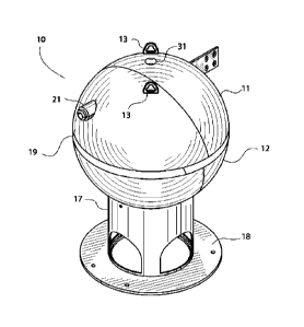
Figure 1 depicts in elevated, quartering perspective, the exterior of the
separator of the
present invention.
Figure 2 represents a vertical cross section showing interior features of the
apparatus of
Figure 1.
Figure 3 is a section similar to Figure 2 shown in elevated perspective to
emphasize the
geometry of fluid flow within the interior of the apparatus of Figure 1.
Figure 4 shows steady-state fluid behavior within the interior of the
separator of Figure 1.
Figure 5 details, as shown in Figure 4, the manner by which gas enters the
flue apparatus of
Figure 1.
3
Date Recue/Date Received 2022-11-04
DESCRIPTION OF A PREFERRED EMBODIMENT
Referring to the figures, the present invention comprises a sand separator
having a tank 10
with vertical axis A surrounded by upper, hemispherical dome 11 atop lower,
hemispherical basin
12. Tank 10 is supported at a select height above a resting surface (not
shown) by stand 17
sufficiently high to allow access to debris exit port 15, discussed in more
detail below. Top dome
11 also may include one or more lifting lugs 13 for maneuvering separator 10
between a
transportation vehicle (not shown) and said resting surface at an installation
site.
Separator tank 10 is adapted to be installed adjacent said wellhead with axis
A oriented
substantially vertically. Vertical orientation takes advantage of gravity to
encourage debris 5 to fall
to the bottom of lower basin 12 for removal through a sand outlet, including
debris exit port 15 and
sand shield 16. Accumulated sand 5 (Figure 4) comprises a relatively viscous
but fluid sand/water
slurry, substantially under wellhead pressure within separator tank 10.
Opening sand exit port 15
allows the slurry to extrude out under pressure, abetting removal. The slurry
first passes through a
choke valve (not shown) to reduce its pressure and velocity and then through
one or more control
valves to a disposal site (neither shown). One having ordinary skill in the
art will recognize that all
known methods of disposal of sand 5 and water 3 are contemplated by the
present invention.
Sand shield 16 straddles debris exit port 15 to support the weight of sand 5
and to prevent
it from clogging sand exit port 15. Sand shield 16 preferably comprises a
horizontal plate spanning
outlet 15 and supported above it by at least three vertical legs. Sand 5 and
other debris passes under
.. said plate and between said legs to enter sand exit port 15. One having
ordinary skill in the art will
recognize that sand shield 16 may have other configurations, such as a sloped
or domed plate and
a different number of support legs, and that said support legs may be oriented
other than vertically,
without departing from the scope of the present invention.
4
Date Recue/Date Received 2022-11-04
The remaining fluid F, comprising mostly natural gas 1, oil and water 3,
eventually exits
sand separator tank 10 at fluid outlet 31 where it proceeds through velocity-
reducing choke valves (not
shown) and onward to be separated into its constituents and processed as
production fluids. If the
wellhead is a gas well, gas 1 is routed to accumulation tanks and/or pipelines
(neither shown), while
oil and liquid precipitates are routed to other storage means (not shown) for
further refining. If it is
an oil well, gas 1 may be flared. Water in both cases usually is a byproduct
for disposal, as it cannot
be re-used without significant processing because it is contaminated with
fracturing fluid chemicals.
One having ordinary skill in the art will recognize that the present invention
is useful for sand and
solid debris removal in all such situations.
As best seen in Figures 2 -4, wellhead fluid F enters separator tank 10
through inlet port 21
disposed through the walls of upper dome 11. Inlet 21 comprises nozzle 22
coupled to and in fluid
communication with the wellhead and conveying fluid F into tank interior 14 of
separator tank 10.
Nozzle 22 extends into tank interior 14 a spaced distance, preferably radially
toward axis A. Further,
nozzle 22 preferably enters tank interior 14 within an entry plane
substantially normal to axis A and
thereby substantially horizontally. One having ordinary skill in the art will
recognize, of course, that
both of such angles (horizontal and radial) relative to axis A at which nozzle
22 enters tank interior
14 can vary significantly without departing from the scope of the present
invention. In a particular
embodiment, the entry plane is disposed approximately half way between the top
of dome 11 at fluid
outlet 31 and the midpoint of vertical axis A where the perimeters of dome 11
and basin 12 meet.
One having ordinary skill in the art will recognize, of course, that the
vertical position of the entry
plane must remain within dome 11 but otherwise can vary significantly without
departing from the
scope of the present invention.
Disposed on the interior end of nozzle 22 distal inlet 21, diverter 23
redirects fluid F toward
the interior wall of upper dome 11, preferably, but not necessarily, still
within said entry plane.
Diverter 23 deflects fluid F at an angle, preferably an obtuse angle, to the
centerline of nozzle 22.
This causes fluid F to encounter the concave wall of upper dome 11 at impact
location I (Figure 3)
5
Date Recue/Date Received 2022-11-04
offset a spaced angular displacement around the interior perimeter of dome 11
from the point of
entry of nozzle 22 into tank interior 14.
One having ordinary skill in the art will recognize that the location of
impact point I and the
angle at which fluid F encounters the walls of dome 11 may vary. In a
particular embodiment,
.. impact location I is between forty-five (45 deg.) degrees and one hundred
thirty-five (135 deg.)
degrees. In another particular embodiment, impact location I is substantially
ninety (90 deg.) degrees
offset from inlet port 21, whereby fluid F impacts the walls of dome 11 at
substantially forty-five
(45 deg.) degrees of angle. Diverter 23 accordingly is at substantially forty-
five (45 deg.) degree
angle to nozzle 22. Thus, fluid F impacts the walls of dome 11 at a
significant angle, and is
deflected by said walls to circulate around dome 11. Because dome 11 walls are
generally concave
downward, fluid F also is diverted downward toward and into basin 12 in a
substantially helical path.
Disposed across and on either side of said impact location I, concave erosion
plate 25
intercepts fluid F as it encounters the curved walls of dome 11. Erosion plate
25 retards erosion
caused by fluid F still under substantially full wellhead speed and pressure
and bearing significant
amounts of solid debris particles. Preferably, erosion plate 25 is
sufficiently large and shaped to
fully cover impacting fluid F and to protect dome 11 walls from erosion. In a
particular
embodiment, erosion plate 25 comprises a three-quarter (3/4 in.) inch thick
lamination of concave
steel plate lining said upper dome wall, centered on location I and extending
in both horizontal
directions from location I approximately fifteen (15 deg.) degrees of angular
displacement, as well
as extending in both vertical directions for a displacement of approximately
five (5 deg.) degrees.
As best seen in Figure 3, fluid F circulates axially and helically downward
around the interior
walls of dome 11 and into basin 12, expanding and slowing as it goes. Further,
fluid F spreads as
it circulates, spiraling radially inward toward axis A, slowing still further.
This spreading and
slowing process causes solid debris such as sand 5 to precipitate out of
solution and to settle toward
.. sand outlet 15. Sand 5 periodically is removed through exit port 15,
leaving a minimum level of
sand 5 within lower basin 12 above which heavier liquid components of fluid F
accumulate. Thus,
6
Date Recue/Date Received 2022-11-04
lower basin 12 accumulates and stores not only sand 5 but also heavier liquid
constituents of fluid
F, freeing gas 1 to rise toward flue 40.
Continuing with Figures 2 - 4, downcomer 33 descends coaxial with axis A a
spaced distance
into interior 14 to terminate in downwardly opening mouth 34. Fluid F,
substantially freed of solid
sand and other debris 5, exits through mouth 34 to proceed to other production
stages downstream
of separator tank 10. In a particular embodiment, downcomer preferably is a
six (6 in.) inch
Schedule 40 or greater circular pipe reaching substantially twelve (12 in.)
inches into interior 14
below outlet 31.
Coupled to downcomer 33 by clamp 44 a spaced distance above mouth 34, flue 40
comprises
conical, downwardly opening chimney 43 that directs fluid F toward mouth 34.
It has a horizontal,
substantially circular perimeter forming a cone base approximately three-
fourths of the diameter of
separator 10 and a vertical height of approximately one-fourth of said
diameter of separator 10.
Chimney 43 couples to downcomer 33 about three and one-half (3 1/2 in.) inches
above mouth 34,
and flares downward coaxial with vertical axis A to end in a margin or
perimeter 44 disposed below
the entry plane of nozzle 22. Thus, fluid F must flow downward, below
perimeter 44, as described
above, before it can enter outlet 31.
Arrayed around perimeter 44 of chimney 43, a plurality of radially outward
facing notches
45 serve two putposes. First, notches 45 locate and assist press breaking of
the plate steel of
chimney 43 into radial bends which give it its conical shape, as discussed
below. Second, notches
45 strain and break fluid F into a plurality of small rivulets (Figure 5) as
it flows around perimeter
44, thus inducing fluid F to flow in an even more laminar manner as it enters
flue 40. Preferably,
notches 45 for chimney 43 are evenly spaced and continuous around perimeter
44, giving chimney
43 a serrated margin. In a particular embodiment, notches 45 are approximately
one (1 in.) inch
wide at perimeter 44 and extend radially inward approximately one-and-one-
fourth (1 1/4 in.) inches
toward downcomer clamp 41. One having ordinary skill in the art will recognize
that the number,
shape and size of notches 45 are a design parameter selected for the wellhead
shut-in conditions of
7
Date Recue/Date Received 2022-11-04
a given gas field, and that all such numbers, shapes and sizes, including no
notches 45 at all, are
within the scope of the invention.
Disposed radially inward from perimeter 44 and coupled to the underside of
chimney 43,
annular collar 50 is coaxial with and parallel to axis A.
Collar 50 attaches by its upper margin to
the underside of chimney 43 with a continuous, fluid-tight weldment, and
extends vertically
downward to terminate approximately coplanar with perimeter 44. Preferably,
collar 50 includes
a plurality of downwardly opening, substantially semi-circular scalloped
openings 52 along its lower
margin. Scalloped openings 52 extend approximately half the height of collar
50, and match
substantially the height and area of notches 45. Preferably, scalloped
openings 52 are evenly spaced
around the lower margin of collar 50 and angularly offset around axis A so
that they do not line up
with notches 45 in perimeter 44.
Collar 50 thus forms a short dam intercepting and diverting the flow of fluid
F coming from
notches 45. Fluid F passes under perimeter 44 through notches 45, and then
encounters collar 50
which further slows it. The individual rivulets (not shown) of fluid F thus
divert their pathway and
flow through scalloped openings 52, slowing the speed of fluid F even further.
In such manner, fluid
F enters the interior of flue 40 far more calmly than it enters interior 14 of
separator tank 10 at inlet
21.
Fluid F remains under high pressure from the wellhead, but its speed has
been reduced and its
laminar flow increased as it approaches outlet 31.
Though fluid F entering flue 40 may contain other constituents, it primarily
comprises gas
1, oil and water 3. This admix of gas and water is considerably lighter than
fluid F had been when
it entered separator 10 at inlet 21, largely because of the removal of solid
debris 5. Under slower
movement but continued wellhead pressure, some lighter constituents of fluid
F, primarily gas 1, can
separate out from fluid F and form pockets or layers of such undissolved
constituents.
As it continues to circulate, fluid F rises buoyantly toward the top of flue
40, forming a fluid
dome 62 comprising primarily fluid F substantially devoid of debris 5. Fluid
dome 62 reaches
8
Date Recue/Date Received 2022-11-04
toward, but never quite enters, mouth 34 of downcomer 33. Instead, a high-
pressure gas dome 61
of undissolved gas 1 builds atop fluid dome 62 against the underside of
chimney 43, the outer wall
of downcomer 33 and above and across mouth 34 above fluid dome 62. Gas 1
thereby is channeled
into downcomer 33 and exits separator tank 10 through outlet 31. See Figure 4.
Gas dome 61 has the effect of compressing other constituents of fluid F in
fluid dome 62
which have not yet recombined with gas 1, said constituents largely being
liquids such as water 3,
oil and liquid gas precipitates. At the margin between fluid dome 62 and gas
dome 61, gas 1
partially recombines with water 3 and oil from fluid dome 62, creating an
admix of the lighter
constituents of fluid F. The admix then flows into mouth 34 and through outlet
31, leaving heavier
constituents of fluid F, including sand 5, inside separator tank 10.
Fabrication
Preferably, diverter 23 comprises an angled portion of steel pipe similar to
nozzle 22. One
having ordinary skill in the art will recognize, however, that diverter 23
could be an elbow, angled
deflector plate, or other device, and it could be reinforced against erosion,
without departing from
the scope of the present invention. Preferably, nozzle 22 comprises a high-
grade steel pipe of at least
Schedule 40 and having an inner diameter of substantially four (4 in.) inches.
Chimney 43 preferably
comprises a circular steel plate sufficiently thick to remain rigid though
buffeted by the high speed
and pressure of fluid F. Chimney 43 is fonned into a truncated cone by press-
breaking it at spaced
intervals around its perimeter. In a particular embodiment, chimney 43 is one-
half (Ain.) inch thick,
has a base diameter of three (3 ft.) feet and a height of one (1 ft.) foot.
Separator 10's dome 11 and basin 12 are fabricated from high strength steel of
sufficient
thickness to withstand fluid pressures from a natural gas wellhead (not shown)
downstream of which
separator 10 is coupled and with which it is in fluid communication. Dome 11
and basin 12
preferably are congruent and mate at their circular, hemispherical margins and
sealed closed with
weldment 19 also capable of withstanding said wellhead fluid pressures. One
having ordinary skill
9
Date Recue/Date Received 2022-11-04
in the art will recognize that separator 10 may vary in size and shell
thickness depending upon the
wellhead application for which it is designed.
Depending upon the pressures of the gas field in which said wellhead is
located, shut-in
pressures may range from as little as 1000 psig to as much as 15,000 psig.
Further, gas well
pressures from time-to-time may surge substantially above such typical field
shut-in pressures. For
greater wellhead shut-in pressures, larger diameter separators 10 create a
trade-off between diameter
and wall thickness. Finally, separator 10 also must be capable of the volume
output of water and gas
of said wellhead effluent fluid.
Example 1
By way of a First Example, the hydrostatic pressures experienced during 2010
in the Barnett
Shale gas field in and around Fort Worth, Texas, typically fell into the range
of 1000 - 1500 psig.
Volumes from the Barnett Shale play typically ran as much as 10 million cubic
feet (MMCF/da.) of
natural gas per day with a water content of 2000 barrels (bbls./da.) per day.
For such relatively low wellhead shut-in pressures at such volumes, a
particular embodiment
of separator 10 has an outside diameter of approximately fifty-four (54 in.)
inches with
approximately three (3 in.) inches of wall thickness. This provides an
internal diameter of
approximately forty-eight (48 in.) inches, resulting in an interior volume of
approximately 33.5 cubic
feet, a volume sufficient for most applications. This is the equivalent of
almost three 16-inch
diameter cylindrical sand separator towers standing eight feet tall, thus
providing a significant
efficiency in overall size and weight.
Example 2
As a Second Example, a wellhead shut-in pressure of 5000 psig dictates that
separator 10
walls must increase in thickness, possibly reducing the internal diameter of
separator 10 too much
for the expected throughput volumes. This requires that its outside diameter
increase to
accommodate thicker walls that can withstand the increased pressure while the
internal diameter of
Date Recue/Date Received 2022-11-04
separator 10 remains sufficiently large for the volume throughput of natural
gas and fluid F. Thus,
for the same throughput as the First Example above, separator 10 requires wall
thicknesses of three
and one-half (3 1/2 in.) to four (4 in.) inches, requiring an outside diameter
of two to four ( 2 in. to
4 in.) inches greater than the 54 inches of the First Example. This is a
modest increase over the size
requirement for the First Example, though its weight will increase noticeably.
Operation
In operation, wellhead effluent fluid F enters separator 10 through inlet 21
and nozzle 22, at
substantially unchoked wellhead pressures and velocity. Though fluid F
immediately experiences
a release of pressure because of the increased volume of interior 14 of
separator 10 in contrast to
wellhead piping (not shown), the pressure within separator 10 remains high. As
fluid F circulates
inside separator 10 and descends within tank interior 14, however, gas 1
separates from fluid F and
rises to enter flue 40. With gas 1 released from the stream of fluid F now
substantially containing
mostly water 3 and sand 5, the velocity of fluid F slows considerably more. As
fluid F drops low
enough within tank interior 14 to enter flue 40 below perimeter 44, it slows
even further while
turning the corner and beginning to rise inside chimney 43. One having
ordinary skill in the art will
recognize that fluid F at this point is primarily an admix of oil and water 3,
gas 1 having already
separated out and risen into chimney 43. Fluid F rises until it approaches
mouth 34, where it
recombines with a layer of gas 1 and exits separator 10 through fluid outlet
31.
Thus, the helical circulation of fluid F within tank 10 substantially
increases the overall
length of its pathway while it is in tank 10. This in turn substantially
increases the drop in speed of
fluid F and maximizes the time debris 5 has to settle out of fluid F. Further,
such a helical path, and
the circular manner in which the present invention induces it, increases the
laminar nature of the flow
of fluid F, further stabilizing and calming it for debris 5 to settle out.
This is in contrast to most prior
art which directs fluid F straight toward a deflector plate which abruptly
interrupts fluid F and
diverts it downward toward the bottom of tank 10, causing considerable non-
laminar turbulence and
disrupting the settlement action of debris 5.
11
Date Recue/Date Received 2022-11-04
While the invention has been particularly shown and described with reference
to one or more
particular embodiments, it will be understood by those skilled in the art that
various changes in form
and detail may be made therein without departing from the spirit and scope of
the invention. For
example, though separator 10 has been discussed above in the context of
natural gas exploration and
production, it works as well for petroleum exploration and production. The
lighter constituents of
fluid F in this context are primarily petroleum, which escape into flue 40
around perimeter 44 and
recombines at mouth 34 with fluid F substantially freed of sand 5, as
discussed for natural gas 1.
Also, tank 10 has been depicted and discussed as being spherical in shape,
with its walls
substantially circular in cross section, but it could comprise other shapes,
such as ovate, tetrahedral
or even cubical, as long as its interior 14 did not create so much turbulence
that it overcomes the
slowing and calming effect of the helical rotation of fluid F for the puipose
of letting debris 5 settle
out for removal.
12
Date Recue/Date Received 2022-11-04