Note: Descriptions are shown in the official language in which they were submitted.
WO 2021/130211
PCT/EP2020/087599
1
Applicator tube
Technical field
The present invention relates to an applicator tube and a kit of parts for
delivering a
5 viscous fluid, such as a paste, more particularly an endoscopic and/or
laparoscopic
applicator tube for delivering a viscous fluid, such as a paste, as well as a
method of
emptying the applicator tube, such as the endoscopic and/or laparoscopic
applicator
tube. Advantageously, the applicator is used for delivering a viscous fluid
within an
insufflated body part.
Background
A viscous fluid, such as a paste, may be precisely applied to a target site by
use of a
syringe. A syringe comprises a plunger, or piston, fitted to a barrel with an
opening,
where the barrel comprises the paste. By pushing or translating the syringe
plunger
15 along the barrel, the paste, typical in the form of an essentially non-
compressible thick
viscous composition, is discharged from the opening of the syringe barrel in a
controlled manner. Thus, a paste may be delivered to a target site with high
spatial
precision and in a flexible dosage, by use of a syringe.
20 The delivery of a paste to a specific target site and in a precise
amount, is especially
important for pastes, which are applied for medical purposes, such as for
surgical
applications_ For example, haemostatic compositions for surgical applications
are
typically in the form of a paste.
25 An example of an effective surgical haemostat is a gelatine paste
comprising a
haemostatically effective amount of thrombin. Thrombin is a dotting agent, and
may
thus be used to control the bleeding at a haemorrhaging site. However, for the
medical
paste to be haemostatically efficient, it is important that an effective
concentration of
the thrombin is present in the paste, and that the thrombin is uniformly
distributed in the
30 paste, and that the paste has a suitable viscosity and rheology for
precise and fixed
positioning.
For endoscopic and/or laparoscopic procedures, the target site is not directly
accessible for a syringe. Instead the paste is applied from the syringe via an
applicator
35 tube, where the applicator tube may be introduced into the body via a
trocar port.
CA 03158722 2022-5-17
WO 2021/130211
PCT/EP2020/087599
2
Hence, the syringe facilitates a precise amount of paste discharged, and the
applicator
tube placed within the trocar and associated obturator allows for precise
application of
the paste to a distal target site.
5 Discharge or dosage of paste from the applicator tube at the distal
target site implicitly
means that the tube is filled with a residual or remaining amount of paste. If
the
residual paste is not subsequently discharged and e.g. applied at a target
site, the
paste is wasted. Furthermore, the residual paste within the tube may be
subject to
phase changes, such as hardening of the paste, and when occurring within the
tube,
10 this may lead to mechanical stresses and damage of the tube.
To ensure utilization of the residual paste and to avoid damage of the
devices, paste
application typically implies two steps: 1) application of paste by depressing
the plunger
of the paste containing syringe, and 2) the residual paste in the applicator
tube is
15 discharged by use of a ram rod or stylus.
The second process step typically requires the use of two hands, which is
especially
challenging in laparoscopic procedures. US 2018 303531 discloses a hemostatic
delivery tube, where the residual paste is discharged via a stylus advancing
through
20 the tube. When the stylus extends through the entire tube, any
remaining paste is
avoided.
Summary
Surgical procedures are typically subject to time constraints, and the time
consumption
25 of each medical procedure thus of importance. For example, the time
consumption may
be critical when using a haemostatic paste for inhibiting bleedings as the
surgeon will
have to interrupt his procedure while waiting for the applicator with the
haemostat to be
prepared. Thus, the preparation time of the applicator may cause increased
blood loss
and longer operating time of the surgical procedure.
For more efficient paste application procedures, improved applicator tubes are
needed.
A first aspect of the invention relates to an applicator tube for delivering a
paste from a
syringe, comprising:
35 - a delivery tube comprising a distal end for delivering the
paste,
CA 03158722 2022-5-17
WO 2021/130211
PCT/EP2020/087599
3
- a valve system attached to a proximal end of the delivery tube and
configured for attachment to the syringe, the valve system having a first
configuration allowing aspiration of gas from the tube surroundings, and a
second configuration allowing expression of aspirated gas into the delivery
5 tube,
such that the applicator tube is configured for transporting a volume of
aspirated gas into and through the delivery tube when an attached syringe
is aspirated and expressed.
10 A second aspect of the invention relates to an endoscopic and/or
laparoscopic
applicator tube for delivering a paste from a syringe, comprising:
- a delivery tube comprising a distal end for delivering the paste,
- a valve system attached to a proximal end of the delivery tube and
configured for attachment to the syringe, the valve system having a first
15 configuration allowing aspiration of gas from the tube
surroundings, and a
second configuration allowing expression of aspirated gas into the delivery
tube,
such that the applicator tube is configured for transporting a volume of
aspirated gas into the delivery tube when an attached syringe is aspirated
20 and expressed.
A third aspect of the invention relates to a method of emptying an applicator
tube,
comprising the steps of:
a) providing the applicator tube according to the first or second aspect,
25 b) attaching a syringe to the delivery tube,
c) aspirating gas into the syringe,
d) expressing the gas from the syringe into the delivery tube, whereby the
applicator tube is emptied.
30 A fourth aspect of the invention relates to a kit of parts, comprising:
a delivery tube, and
a valve system, wherein the valve system is configured to be detachably
attached to a
proximal end of the delivery tube, and further configured for attachment to a
syringe,
the valve system having a first configuration allowing aspiration of gas from
the
surroundings, and a second configuration allowing expression of aspirated gas
into the
35 delivery tube.
CA 03158722 2022-5-17
WO 2021/130211
PCT/EP2020/087599
4
In a preferred embodiment, the kit of parts is for an applicator tube
according to the first
aspect of the invention.
5 The present disclosure provides an improved applicator tube, which
facilitates a faster,
more simple and more efficient paste application, including emptying the
applicator
tube, where the amount of wasted paste is reduced. Particularly, the present
applicator
tube facilitates emptying of the applicator from residual paste without the
use of
separate additional parts, such as a stylus, and without the need of the
additional steps
10 associated with introducing a separate part, such as a stylus, because
of a valve
system attached to the delivery tube of the applicator tube. The emptying of
the
applicator tube may alternatively, or additionally, facilitate that the
applicator tube can
be easily reused or recycled. After use, the residual paste may be easily
discharged as
waste, and the applicator tube immediately reused with a different paste.
In a preferred embodiment, the valve system comprises at least one one-way
valve.
More specifically, the present applicator tube facilitates emptying of the
applicator from
residual paste immediately after discharging paste from the tube delivered
from a
20 syringe, and without disconnecting the syringe delivering the paste,
because of a valve
system attached to a proximal end of the delivery tube and configured for
attachment to
the syringe, the valve system having a first configuration allowing aspiration
of gas,
such as air, from the surroundings, and a second configuration allowing
expression of
aspirated gas, such as air, into the delivery tube, such that the applicator
tube is
25 configured for transporting a volume of aspirated gas, such as air,
into the delivery tube
when an attached syringe is aspirated and expressed.
To reduce the risk of injecting detrimental gasses and detrimental amounts of
gasses
into the body, the aspirated gas is advantageously a gas that is sufficiently
soluble in
30 bodily fluids, such as blood. For example, injection of large amounts
of air into a body
cavity may cause air embolisms. Hence, advantageously, the gas is aspirated
from a
gas container comprising a well defined composition, and located in the tube
surroundings. Alternatively, or additionally, the gas is aspirated from the
tube
surroundings placed within the body. For endoscopic and/or laparoscopic
procedures,
35 the distal part of the tube is typically positioned within an
insufflated body part, meaning
CA 03158722 2022-5-17
WO 2021/130211
PCT/EP2020/087599
that the cavity of the body part has been filled with gas to inflate the
cavity to obtain
more workroom during the laparoscopic procedure. Examples of typical
insufflation
gases are air, CO2, nitrous oxide (N20), helium (He).
5 In a preferred embodiment of the disclosure, the aspirated gas is air
from the tube
surroundings, and/or an insufflation gas selected from group of air, CO2,
nitrous oxide
(N20), helium (He), and combinations thereof.
Description of Drawings
10 The invention will in the following be described in greater detail with
reference to the
accompanying drawings.
Figure 1 shows a cross-sectional view of an embodiment of the applicator tube
according to the present disclosure.
Figure 2 shows a perspective view of an embodiment of the applicator tube
according
15 to the present disclosure.
Figure 3 shows a cross-sectional view of an embodiment of the proximal end of
an
applicator tube according to the present disclosure.
Figure 4 shows a cross-sectional view of another embodiment of the proximal
end of
an applicator tube according to the present disclosure.
20 Figure 5 shows an embodiment of a process for emptying the applicator
tube according
to the present disclosure.
Figure 6 shows a perspective view of an embodiment of the applicator tube,
where the
enhanced sections shown in circles, shows respectively the attachment to the
syringe,
and embodiments of the position of the valves within the valve system.
25 Figure 7 shows an embodiment of an applicator tube according to the
present
disclosure placed within an insufflated body part, where gas is either
aspirated from the
proximal tube surroundings (A), or insufflation gas is aspirated from the
distal tube
surroundings (B).
Figure 8 shows an embodiment of an applicator tube according to the present
30 disclosure placed within an insuffiated body part, where insufflation
gas is aspirated
from the distal tube surrounding (A), a close-up of the embodied distal tube
section (B),
and a cross-sectional view of a tube section (C).
Figure 9 shows an embodiment of a valve system according to the present
disclosure,
in the form of a two valve function combination valve, such as a
duckbill/umbrella
35 combination valve. (A) The valve may be integrated into the proximal
end of the
CA 03158722 2022-5-17
WO 2021/130211
PCT/EP2020/087599
6
delivery tube, such as integrated into the transition unit, and the inner
duckbill valve
may be either closed, as seen to the left in (B), or open for flow in the
direction of the
pointed beak, as shown by arrow to the right in (B). Correspondingly, the
outer
umbrella valve may be either closed, as seen to the right in (C), or open for
flow in the
5 direction of the inverted umbrella, as shown by arrow to the right in
(C).
Figure 10 shows embodiments of the applicator tube lumens according to the
present
disclosure, where (A) and (B) show perspective views of the distal end of the
applicator
tube, and (C-G) show cross-sectional views of the lumen configuration, where
the
second lumens may be placed within the delivery tube wall (C), or on the
outside of the
10 delivery tube wall (D, F, G), or inside the delivery tube wall (E).
Detailed description
The invention is described below with the help of the accompanying figures. It
would be appreciated by the people skilled in the art that the same feature or
15 component of the device are referred with the same reference numeral in
different
figures. A list of the reference numbers can be found at the end of the
detailed
description section.
Applicator tube
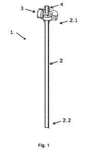
20 Figure 1 shows an embodiment of an applicator tube 1 according to the
present
disclosure, comprising a delivery tube 2 with a proximal end 2.1 and a distal
end 2.2,
where the proximal end is adapted for forming a connection to a syringe. When
a
syringe containing a paste is attached to the proximal end, said paste may be
delivered, dispensed or discharged from the distal end of the delivery tube by
pushing
25 the plunger, whereby the paste is first transferred from the syringe
into the delivery
tube, and from the delivery tube expelled through it's distal end.
The applicator tube is advantageously applied for endoscopic and/or
laparoscopic
surgical procedures, where the delivery tube is introduced into the internal
body via the
30 hollow tube, or cannula, of a trocar. Typically, a trocar is placed
through the abdomen
during the laparoscopic surgery, and subsequently used as a portal for the
following
procedures. Thus, the endoscopic and/or laparoscopic applicator tube
advantageously
have a length, diameter and stiffness compatible with and enabling easy
manipulation
and precise positioning of the applicator tube within a trocar. Particularly,
the applicator
35 tube must have a length, diameter, and stiffness or hardness allowing
manipulation of
CA 03158722 2022-5-17
WO 2021/130211
PCT/EP2020/087599
7
the distal end of the applicator tube via the proximal end, which is
accessible to the
user located at the trocar port.
In an embodiment of the disclosure, the applicator tube is an endoscopic
and/or
5 laparoscopic applicator tube. In a further embodiment, the applicator
tube is adapted
for insertion into a trocar. In a further embodiment, the applicator tube has
a length
between 20¨ 150 cm, more preferably between 25 ¨ 80 cm, such as between 30 ¨
60
cm. In a further embodiment the applicator tube comprises a tube with an
internal
diameter of between 2 ¨ 15 mm, more preferably between 3 ¨ 8 mm, such as
between
10 4 ¨ 6 mm or 3- 5 mm. In a further embodiment, the applicator tube
comprises a tube
containing a volume of between 3-20 ml, preferably between 4-10 ml or 5-10 ml,
such as 5 ml.
In a further embodiment, the applicator tube comprises a tube with a stiffness
of equal
15 to or above 0.5, 1.5 or 2 GPa as measured by tensile test according to
the appropriate
standard EN10002, e.g. EN10002-1 (ISO 6892-1) as standard for metal
stiffness/tensile E modulus, and/or ISO 527-1/-2, ISO 527-4, ISO 527-5, ASTM
0638
as standard for the tensile E-modulus for plastics, polymers, composite
material, and/or
ISO 178/ASTM 0790 as standard for the flexural E-modulus for plastics,
polymers,
20 composite material. More preferably, the applicator tube comprises a
tube with a
stiffness above 50 or 60 GPa. Examples of materials with a stiffness above 0.5
or 1.5
GPa include plastics, metals, polymers, glass, glass fibers, carbon fibers,
polymer
fibers, composites such as fiber-reinforced materials and combinations
thereof. In an
embodiment of the disclosure, the applicator tube comprises a tube consisting
of a
25 material selected from the group of: metals, plastics, polymers, glass,
glass fibers,
carbon fibers, polymer fibers, composites such as fiber-reinforced materials
and
combinations thereof.
In a further embodiment, the applicator tube comprises a tube with a stiffness
below
30 0.5 GPa. Such materials have in addition, or alternatively, a preferred
hardness. An
example of a material with a stiffness below 0.5 GPa is a thermoplastic
elastomer with
a Shore Durometer A and/or D hardness according to standard ISO 868/ASTM
D2240.
For handle ergonomics and for facilitating precise manipulation and
positioning of the
35 applicator tube within the trocar, the applicator tube advantageously
comprises a
CA 03158722 2022-5-17
WO 2021/130211
PCT/EP2020/087599
8
handle or a grip attached to the proximal end of the delivery tube. To improve
the
compactness and robustness of the applicator tube, the handle is
advantageously in
the form of a transition unit between the delivery tube and the syringe, such
that the
syringe is attachable to the transition unit. Figures 1-2 show embodiments of
an
5 applicator tube comprising a transition unit 3, which may further act
as a handle.
In an embodiment of the disclosure, the applicator tube comprises a transition
unit
attached to the proximal end of the delivery tube, wherein preferably the
transition unit
is adapted as a handle.
To ensure easy attachment of the syringe to the delivery tube, and further to
ensure
easy and safe transfer of the paste from the syringe into the delivery tube,
the syringe
and delivery tube are advantageously detachably attachable. An example of a
detachable attachment is a Luer fitting or Luer lock, where a male-taper
fitting of a first
15 component is connected to a mating female part of a second component. A
Luer fitting
further has the advantage of providing an essentially leak-free connection
between the
two components. Hence, the applicator tube advantageously comprises a Luer
lock 4
for attaching the syringe, placed at the proximal end adapted for attaching
the syringe,
as exemplified in Figures 1-2. For example, the Luer lock may be placed at the
20 proximal end of the delivery tube or at the transition unit. The Luer
lock may be
according to ISO 80369-7.
In an embodiment of the disclosure, the applicator tube comprises a Luer lock
for
attaching a syringe. In a further embodiment, the delivery tube and/or the
transition unit
25 comprises a Luer lock for attaching a syringe.
The attachable syringe is advantageously pre-filled with paste before being
attached to
the delivery tube. Alternatively, an empty syringe may be attached to the
delivery tube,
where the empty syringe is further configured for being filled with paste in
the same
30 manner as a cartridge by removing the plunger, while in the attached
configuration.
Further alternatively, an empty syringe, optionally pre-filled with air, may
be attached to
the delivery tube to expel air, as described below.
CA 03158722 2022-5-17
WO 2021/130211
PCT/EP2020/087599
9
In an embodiment of the disclosure, the applicator tube is adapted for
attaching a pre-
filled syringe, such as a syringe pre-filled with paste. In another
embodiment, the
applicator tube is adapted for attaching an empty syringe.
5 It follows that the presently disclosed applicator tube for delivering
a paste from a
syringe may be used with any type of syringe. Examples of syringes include
single
chamber syringes and syringes comprising multiple chamber, such as dual
chamber
syringes, where the contents of the multiple chambers may be mixed prior to
injection.
10 To facilitate easy paste delivery from the applicator tube, the plunger
of the syringe is
adapted to be pushable by use of a users hand or thump. To ensure paste
delivery by
application of moderate hand pressure, the applicator tube or delivery tube is
adapted
to have a sufficiently large internal diameter at the distal end discharging
the paste. To
further facilitate precise delivery of the paste at a target site, the
applicator tube or
15 delivery tube advantageously have a sufficiently small internal
diameter at the distal
end. Easy and precise delivery of a paste from a syringe and applicator tube
may be
obtained by an applicator tube or delivery tube comprising a cannula. Further
advantageously, the delivery tube is a cannula, where by the term "cannula" is
meant a
tube that can be inserted into the body. For example it may be a tube, which
concludes
20 with a spike/angular open end to provide fluid access through the
entire cannula.
In an embodiment of the disclosure, the delivery tube comprises or is a
cannula.
Formable distal section
25 To ensure easy manipulation, as well as precise and flexible paste
delivery, the
applicator tube advantageously comprises a formable section. Optionally, the
entire
applicator tube is formable. Advantageously, the formable section is at least
a distal
section of the tube, such as a formable distal tip of the delivery tube. Thus,
the tube
may be formed or shaped into a desired shape or configuration by applying a
30 deformation force, typically by hand, to bend the formable section. The
tube will then
retain the configuration until a further deformation force is applied to form
the tube into
a different configuration.
The formable section may be obtained by the formable section comprising a
malleable
35 member, as described in WO 2011/047753. The malleable member is made of
a
CA 03158722 2022-5-17
WO 2021/130211
PCT/EP2020/087599
suitable material, which is configured to maintain a configuration after a
deformation.
For example, the malleable member may be a metal, e.g. comprising aluminum or
an
aluminum alloy, and be in the shape of a wire or mesh, which thereby may be
formed/deformed into a desired shape, preferably by manual bending. The
malleable
5 member is integrated into the applicator tube or the delivery tube,
e.g. the malleable
member may be received within a lumen of the applicator tube, thereby forming
a
formable section. Examples of tube lumens, wherein a malleable member in the
form of
a wire or a mesh lumen may be integrated are shown in Figure 10. The delivery
tube
comprises a first lumen 7 for discharging the paste, and at least one of the
surrounding
10 second lumens 8 may receive a malleable member. For example, a
malleable wire may
be located within a lumen within the delivery tube wall, as shown in Figure
100, or
located in a lumen placed on the outside or inside of the delivery tube wall
(Figure 10D-
G). Similarly, a malleable mesh may be rolled into a malleable cylinder, which
may be
located within any of the lumens of Figure 10. Alternatively, a malleable mesh
may be
15 located in a lumen, which is concentric with the delivery tube opening,
as shown in
Figure 10G.
In an embodiment of the disclosure, the applicator tube comprises a formable
distal
section configured to be shaped into a desired configuration. In a further
embodiment
20 the formable distal section comprises a malleable member configured to
maintain a
configuration after a deformation, wherein said malleable member optionally is
a
malleable wire or a malleable mesh. In a further embodiment, the malleable
member is
located on the inside, outside, or within the delivery tube wall.
25 Applicator tube emptying
When the applicator tube has delivered paste from the syringe, the applicator
tube
including the entire length of the delivery tube, will be filled with
remaining or residual
paste. To utilize the residual paste, e.g. to apply it to the first target
site or a second
target site, the applicator tube must be emptied. According to the present
disclosure,
30 the applicator tube and particularly the delivery tube, may be emptied
by a gas
pressure, such as an air pressure. The embodiments of the disclosure may be
extended to any type of gas, but will in the following be exemplified based on
air. By
the term emptying is meant removal or cleaning of paste from the applicator
tube. More
specifically the term emptying means removal of residual paste, i.e. the paste
35 remaining in a tube following a paste discharge from the tube.
CA 03158722 2022-5-17
WO 2021/130211
PCT/EP2020/087599
11
Alternatively, or additionally, the applicator tube may be emptied to
facilitate simple,
easy, and controlled reuse or recycling of the applicator tube. After use, the
residual
paste may be discharged and disposed as waste, and the applicator tube
immediately
5 reused with a different paste.
The gas/air pressure required for discharging the residual paste will depend
on factors
such as the internal cross-sectional area of the tube, the length of the tube,
the
stiffness of the tube, the paste viscosity, and the wetting properties between
the paste
10 and the tube material. For easy emptying of the applicator tube, and
particularly the
delivery tube, the delivery tube advantageously have a length, diameter,
stiffness, and
other material properties, which facilitate a produced flow and thus the
emptying
process.
15 In an embodiment of the disclosure, the delivery tube has a length
between 20 ¨ 150
cm, more preferably between 25 ¨ 80 cm, such as between 30 ¨ 60 cm. In a
further
embodiment, the delivery tube comprises an internal diameter of between 2¨ 15
mm,
more preferably between 3 ¨ 8 mm, such as between 4 ¨ 6 mm or 3 -5 mm. In a
further embodiment, the delivery tube comprises a tube containing a volume of
20 between 3-20 ml, preferably between 4-10 ml, such as 5 ml. In a further
embodiment, the delivery tube has a stiffness of equal to or above 0.5, 1.5 or
2 GPa as
measured by the appropriate standard, e.g. tensile test according to the
standard
EN10002, or EN10002-1 (ISO 6892-1) as standard for metal stiffness/tensile E
modulus, and/or ISO 527-1/-2, ISO 527-4, ISO 527-5, ASTM D638 as standard for
the
25 tensile E-modulus for plastics, polymers, composite material, and/or
ISO 178/ASTM
0790 as standard for the flexural E-modulus for plastics, polymers. More
preferably,
the delivery tube has a stiffness above 50 or 60 GPa. In an embodiment of the
disclosure, the delivery tube comprises a material selected from the group of:
metals,
plastics, polymers, glass, glass fibers, carbon fibers, polymer fibers,
composites such
30 as fiber-reinforced nlaterials,and combinations thereof.
For simple and fast emptying, the applicator tube is advantageously configured
such
that the residual paste may be removed and discharged from the distal end of
the
delivery tube by an air/gas pressure generated by a syringe. For example, a
syringe
35 may be pre-filled with air/gas, or aspirated to store air/gas, and then
attached to the
CA 03158722 2022-5-17
WO 2021/130211
PCT/EP2020/087599
12
proximal end of the delivery tube. Upon injecting or expressing the syringe
stored
gas/air into the delivery tube, the generated air pressure causes the residual
paste to
be discharged from the delivery tube.
5 Emptying the applicator tube by use of the moderate gas/air pressure
produced by a
syringe operated by hand further has the advantage that the discharge of paste
from
the delivery tube may be precisely controlled. Advantageously, the rate of
advancing
the piston of the syringe, corresponds to the rate of paste discharge from the
tube.
Hence, precise and controlled paste delivery to a target site may be obtained.
A more efficient emptying procedure may be obtained if the gas/air pressure is
generated by an already attached syringe. This means that the gas/air pressure
is
generated without disconnecting the syringe from the applicator tube. Thus,
the steps
of disconnecting the syringe containing paste, and subsequent attachment of a
syringe
15 containing gas/air is avoided, and a faster and more efficient removal
of the residual
paste is obtained. Emptying by use of a syringe attached to the applicator
tube may be
obtained by the valve system according to the present disclosure.
In an embodiment of the disclosure, a method of emptying the applicator tube
20 comprises the steps oft
a) providing an applicator tube according to the present disclosure,
b) attaching a syringe to the delivery tube,
c) aspirating gas into the syringe,
d) expressing the gas from the syringe into the delivery tube,
25 whereby the applicator tube is emptied.
To further improve the efficiency of the process, the attached syringe may be
the
syringe containing the paste. Thus, when the applicator tube has delivered the
desired
amount of paste from the syringe, the delivery tube is emptied from residual
paste by
30 aspirating gas/air into the syringe without disconnecting the syringe,
and subsequently
expressing the aspirated into the delivery tube.
Preferably, the entire amount of paste contained in the syringe is expressed
before
aspirating gas/air. Hence preferably, the applicator tube is emptied from
residual paste
35 by first expressing any remaining paste from the syringe into the
delivery tube, and
CA 03158722 2022-5-17
WO 2021/130211
PCT/EP2020/087599
13
then aspirating gas/air into the syringe without disconnecting the syringe.
The gas/air
aspirated into the syringe void of paste, is then expressed into the
applicator tube and
particularly the delivery tube.
5 In an embodiment of the disclosure, the attached syringe in (b)
contains paste, and the
method further comprises the step of expressing at least a part of the paste
from the
syringe into the delivery tube before aspirating gas/air in (c).
It follows that the volume of gas/air aspirated from the surroundings in step
(c) is limited
10 by the size of the syringe. Hence, the gas/air pressure generated by
the syringe is
determined by the size of the syringe and the force pushing the plunger. To
facilitate
simple and efficient emptying, the volume of gas/air aspirated from the
surroundings in
step (c) is preferably between 4¨ 100 ml, more preferably between 5-20 ml,
such as
between 10¨ 15 ml or between 5-10 ml.
In an embodiment of the disclosure, the applicator tube is adapted for
aspirating a
volume of gas/air from the surrounding of between 4¨ 100 nnL, more preferably
between 5-20 ml, such as between 10 ¨ 15 ml or between 5-10 ml.
20 Additional volumes of gas/air may be aspirated from the surroundings by
repeating
steps (c) and (d). For example the steps may be repeated at least 2, 3, 4, 5,
or 6 times.
In an embodiment of the disclosure, the steps (c) and (d) are repeated.
25 Figure 5 shows an embodiment of a process for emptying the applicator
tube according
to the present disclosure, where the movement of the plunger is indicated by
arrow.
Figure 5A shows the first step, where the paste, e.g. a gelatin paste, is
expressed until
the syringe is empty. Figure 5B shows the second step, where the plunger of
the
syringe, while still attached to the applicator tube, is pulled back or
aspirated, to fill the
30 syringe with gas/air. Figure 5C shows the third step, where plunger is
injected such that
the aspirated volume of gas/air generates an air/gas pressure into the
applicator tube,
such that the applicator is emptied from the gelatin paste.
Figure 7 shows an embodiment of an applicator tube according to the present
35 disclosure placed within an insufflated body part or body cavity 12,
e.g. an insufflated
CA 03158722 2022-5-17
WO 2021/130211
PCT/EP2020/087599
14
stomach. The insuffiated body part is accessed via a trocar 13, such that the
distal end
of the delivery tube is located within the insuffiated body part, and a
syringe including a
paste is attached to the proximal end of the delivery tube. After expressing
the paste
from the syringe, the syringe plunger may be retracted, and gas 11 from the
5 surroundings may be aspirated into the syringe without removing the
syringe or the
applicator. This is obtained via the valve system described further below, and
the gas
may be aspirated either from the proximal tube surroundings as seen in Figure
7A, or
aspirated from the distal tube surroundings, i.e. in the form of insuffiafion
gas, as seen
in Figure 7B.
In an embodiment of the disclosure, the gas is atmospheric air from the
surroundings.
In another embodiment of the disclosure, the gas is an insuffiation gas
selected from
group of air, CO2, nitrous oxide (N20), helium (He), and combinations thereof.
15 Valve system
Figure 3 shows an embodiment of the valve system 5 according to the present
disclosure, which is attached to the proximal end of the delivery tube 2.
For a compact and robust applicator tube, the valve system is advantageously
20 integrated into the transition unit or handle 3, and the valve system
is further
advantageously configured for attachment to the syringe, e.g. via a Luer lock
4, as
illustrated in Figure 3. However, to reduce the number of parts, the skilled
person will
know that the valve system may also be directly attached to the proximal end
of the
delivery tube.
In an embodiment of the disclosure, the valve system is integrated into the
transition
unit, and/or the proximal end of the delivery tube.
The valve system is configured to have two configurations: a first
configuration allowing
30 aspiration of gas/air from the surroundings, and a second configuration
allowing
expression of aspirated gas/air into the delivery tube. This implies that the
applicator
tube is configured for transporting a volume of aspirated gas/air into the
delivery tube,
when an attached syringe is aspirated and expressed.
CA 03158722 2022-5-17
WO 2021/130211
PCT/EP2020/087599
The skilled person knows that such controlled fluid flows may be obtained by
use of a
valve system, comprising one or more valves, where a valve is defined as a
device that
regulates, directs or controls the flow of a fluids (i.e. gases, liquids, and
fluidized solids,
such as paste and slurries) by opening, closing, and/or partially obstructing
the flow
5 passageway. Thus, an example of a valve includes a flow constriction
element, such as
a protrusion within a fluid passageway, where the protrusion blocks fluid
passage,
when the fluid pressure is below a threshold value, and when the fluid
pressure is
above the threshold valude, the fluid flows and circumvents the protrusion. A
valve
including a flow constriction element is also referred to as a "constriction
valve".
A valve may further be adapted to regulate, direct or control the flow of
specific fluids.
For example, a valve may be adapted to regulate the flow of paste, whereas the
flow of
the gaseous phases are not affected by the valve. An example of a valve
adapted to
regulate the flow of specific fluids is a constriction valve, where the
dimension of the
15 constriction element is configured to allow the flow of gas in both
directions, but only
allow flow of paste of a certain viscosity in one direction. Hence, a
constriction valve
may be adapted to be a two-way valve for the flow of gas, and a one-way valve
for the
flow of paste. For example, a constriction valve may allow the flow of paste
from the
syringe into the dispensing tube, but the paste is not allowed to passage the
20 constriction in the opposite direction.
A valve may further be a one-way valve or check valve, meaning that the valve
only
allows the fluid to flow in one direction. Hence, a one-way valve has two
positions, an
"open" and "closed" position, where in the open position the valve provides
fluid
25 passageway in one direction, and in the closed position provides no
fluid passageway.
The opening/closing of a one-way valve may be operated in response to magnetic
forces, gravity, and/or fluid pressure. For example, a one-way valve may open
in
response to a fluid pressure exceeded a predefined threshold value. A valve
may
further be operated as a one-way valve by being adapted to have a regulated
and
30 controllable flow direction.
In an embodiment of the disclosure, the valve system comprises at least two
valves 5.1
and 5.2 as illustrated in Figure 3. The first valve is a one-way valve or a
valve adapted
to have a controllable flow direction, and the second valve is also a one-way
valve or a
35 valve adapted to have a controllable flow direction. For example, both
the first valve
CA 03158722 2022-5-17
WO 2021/130211
PCT/EP2020/087599
16
and the second valve may be one-way valves, as exemplified in Figure 3.
Alternatively,
the second valve may be a valve adapted to have a controllable flow direction,
as
exemplified in Figure 4, where the second valve is in the form of a flow
constriction
element
Figure 3 shows an embodiment of the valve system comprising two one-way valves
5.1
and 5.2. The valve system has two configurations: a first configuration
allowing
aspiration of air from the surroundings 6 and through the first one-way valve
5.1 and
the second lumen 8, as indicated by solid arrow and the dotted arrow to the
left in
Figure 3, and a second configuration allowing expression of the aspirated air
through
the second one-way valve 5.2 and the first lumen 7, and into the delivery tube
2, as
indicated by solid arrow and the dotted arrow to the right in Figure 3.
A syringe attached to the proximal end of the delivery tube, e.g. at the Luer
lock
illustrated in Figure 3, may be aspirated while in the attached position,
whereby gas/air
is aspirated from the surroundings, through the first one-way valve, and
further
transferred into the syringe, where it may be stored in the barrel. Due to the
valve
system, fluid communication is established only between the surroundings and
the
attached syringe, and the aspirated gas/air will bypass the delivery tube. The
stored
gas/air may subsequently be expressed by pushing the plunger, and due to the
valve
system, the volume of aspirated gas/air will only flow through the second one-
way
valve and into the delivery tube. Hence, the applicator tube is configured for
transporting a volume of aspirated gas/air into the delivery tube, when an
attached
syringe is aspirated and expressed. Example 1 further describes an embodiment
of the
applicator tube configured for use with a syringe comprising a low-viscosity
paste.
Figure 4 shows an embodiment of the valve system comprising a first one-way
valve
5.1 and a second valve 5.2 in the form of a flow constriction element or a
constriction
valve. Similar to Figure 3, the valve system has two configurations: a first
configuration
allowing aspiration of gas/air from the surroundings 6 and through the first
one-way
valve 5.1 and the second lumen 8, as indicated by solid arrow and the dotted
arrow to
the left in Figure 4, and a second configuration allowing expression of the
aspirated
gas/air through the second valve 5.2 and the first lumen 7, and into the
delivery tube 2,
as indicated by solid arrow and the dotted arrow to the right in Figure 4.
CA 03158722 2022-5-17
WO 2021/130211
PCT/EP2020/087599
17
A syringe attached to the proximal end of the delivery tube, e.g. at the Luer
lock
illustrated in Figure 4, may be aspirated while in the attached position,
whereby gas/air
is aspirated from the surroundings, through the first one-way valve, and
further
transferred into the syringe, where it may be stored in the barrel. Due to the
valve
5 system, fluid communication is established essentially only between the
surroundings
and the attached syringe, and the aspirated gas/air will bypass the delivery
tube. Also,
restricted fluid communication may be established between the delivery tube
and the
attached syringe, depending on the dimensions of the constriction element and
the
content of the delivery tube. Particularly, if the constriction element
reduces the cross
10 sectional area of the delivery tube with between 20-90%, and/or the
delivery tube
contains a high-viscous residual paste, aspiration of residual paste is
prevented. The
stored gas/air may subsequently be expressed by pushing the plunger, and due
to the
valve system, the volume of aspirated gas/air will only flow through the
second valve
and into the delivery tube. Hence, the applicator tube is configured for
transporting a
15 volume of aspirated gas/air into the delivery tube, when an attached
syringe is
aspirated and expressed. Example 2 further describes an embodiment of the
applicator
tube configured for use with a syringe comprising a high-viscosity paste.
A valve system configured to have two configurations: a first configuration
allowing
20 aspiration of gas/air from the surroundings via a second lumen, and a
second
configuration allowing expression of aspirated gas/air into the delivery tube
via a first
lumen, may correspondingly be obtained by a two valve function combination
valve,
such as a duckbill/umbrella combination valve, as shown in Figure 9.
25 The combination valve comprises an inner duckbill valve 5.2 having at
least one
deformable flap, e.g. two rotatable flaps, as seen in Figure 9B, where the
flaps form a
sealed connection within a first lumen 7 when exposed to no/low pressure, as
seen in
Figure 9B to the left, and where the flaps are separated to form an opening in
the seal
and the lumen, when exposed to a certain threshold pressure, as seen in Figure
9B to
30 the right Hence, the inner duckbill valve acts as a one-way valve for
flow in the
direction of the beak, as indicated by arrow in the Figure 9B to the right.
The
combination valve further comprises an outer umbrella valve 5.1 comprising a
deformable flap, which may either form a sealed connection within a second
lumen 8,
e.g. towards a surface when exposed to no/low pressure, as seen in Figure 9C
to the
35 left, and when exposed to a pressure above a certain threshold, the
deformable flap
CA 03158722 2022-5-17
WO 2021/130211
PCT/EP2020/087599
18
separates from the surface to form an opening, as seen in Figure 9C to the
right
Hence, the umbrella valve also acts as a one-way valve for flow in a direction
opposite
the beak.
5 Hence, a syringe attached to the proximal end of the delivery tube,
e.g. at the Luer lock
illustrated in Figure 9A, may be aspirated while in the attached position,
whereby
gas/air is aspirated from the surroundings, through the umbrella valve, and
further
transferred into the syringe, where it may be stored in the barrel. Due to the
valve
system, fluid communication is established only between the surroundings and
the
10 attached syringe, and the aspirated gas/air will bypass the delivery
tube. The stored
gas/air may subsequently be expressed by pushing the plunger, and due to the
valve
system, the volume of aspirated gas/air will only flow through the duckbill
valve and into
the delivery tube. Hence, the applicator tube is configured for transporting a
volume of
aspirated gas/air into the delivery tube, when an attached syringe is
aspirated and
15 expressed. Example 3 further describes an embodiment of the applicator
tube
configured for use with a syringe comprising a low-viscosity paste.
In an embodiment of the disclosure, the valve system comprises at least two
valves, or
a two valve function combination valve, such as a duckbill/umbrella
combination valve.
20 In a further embodiment, the valve system comprises at least a first
one-way valve,
and/or a first constriction valve. In a further embodiment, the valve system
comprises at
least two one-way valves. In a further embodiment, the valve system comprises
a valve
with a cross sectional area of between 20-90%, more preferably between 30-80%,
and
most preferably between 40-60% of the cross sectional area of the delivery
tube.
Instead of attaching the valve system directly to the proximal end of the
delivery tube,
the valve system is advantageously integrated into the transition unit or
handle to
obtain a compact and robust applicator tube. Figures 3-4 also shows
embodiments,
where the valve system is integrated into the transition unit 3, which is
shaped as a
30 circular handle. Also the combination valve may be integrated into the
proximal end of
the delivery tube, such as integrated into the transition unit, as shown in
Figure 9A.
Lumen
As described above, the valve system or transition unit may include a first
lumen 7 and
35 a second lumen 8, where the second lumen is configured for aspirating
gas from the
CA 03158722 2022-5-17
WO 2021/130211
PCT/EP2020/087599
19
surroundings via the first valve 5.1, and where the first lumen is configured
for
discharging the aspirated gas through the delivery tube, as well as
discharging the
paste 10, via the second valve 5.2.
5 More specifically, as illustrated in Figures 3-4 and 9, the valve
system or transition unit
comprises a first and a second lumen, where the first lumen 7 has a first
proximal
opening and a first distal opening, the first proximal opening corresponding
to the
attachment to the syringe, and the first distal opening being in fluid
communication with
the delivery tube, such that the first lumen is configured for discharging the
paste and
10 the aspirated gas to a target site. The second lumen 8 has a second
proximal opening
and a second distal opening, where the second distal opening is in fluid
communication
with the surroundings, such that the second lumen is configured for aspirating
gas from
the surroundings at the second distal opening. Optionally, the first proximal
opening
and the second proximal opening are the same as illustrated in Figures 3-4 and
9, such
15 that they correspond to the attachment to the syringe.
In an embodiment of the disclosure, the valve system or the transition unit
comprises a
first lumen having a first proximal opening and a first distal opening,
wherein the first
distal opening is in fluid communication with the delivery tube, and at least
one second
20 lumen having a second proximal opening and a second distal opening,
wherein the
second distal opening is in fluid communication with the tube surroundings. In
a further
embodiment, the first proximal opening and the second proximal opening are the
same.
It follows that the second distal opening acts as the entry point for
aspirating gas from
25 the surroundings and into the syringe. The second distal opening may be
located within
a proximal end of the applicator tube or delivery tube, as illustrated in
Figure 7A,
whereby gas is consequently aspirated from the proximal tube surroundings,
i.e. the
atmospheric vicinity of the operator. The second distal opening may also be
located
within a distal end of the applicator tube or delivery tube, as illustrated in
Figure 7B.
30 Consequently, gas is aspirated from the distal tube surroundings, e.g.
the insufflated
body part.
Figures 3-4 show an embodiment, wherein the second distal opening is located
within
a proximal end of the applicator tube, such as within the transition unit.
This has the
35 advantage of a simple and compact design of the second lumen 8, e.g.
the extension
CA 03158722 2022-5-17
WO 2021/130211
PCT/EP2020/087599
of the second lumen may be short and oriented perpendicularly to the first
lumen 7, as
shown in Figures 3-4. Moreover, the second lumen may be in fluid communication
with
a gas container, which optionally is directly detachably attached to the
second distal
opening.
5
In an embodiment of the disclosure, the second distal opening is located
within a
proximal end of the delivery tube, such as within the transition unit In a
further
embodiment the extension of the second lumen is oriented at an angle from the
extension of the first lumen, such as extending perpendicular to the first
lumen. In a
10 further embodiment, the second distal opening is in
fluid communication with a gas
container.
Alternatively, the second distal opening is located within a distal end of the
applicator
and delivery tube, as illustrated in Figure 8. This has the advantage that
insufflation gas
15 may be used for emptying the applicator tube. In this
case, the second lumen 8 for the
aspirating gas 11 extends in parallel with the first lumen 7 and the delivery
tube, which
delivers the paste 10 to the target site, as seen in Figure 8A and B. To
reduce the risk
of aspirating blood or other bodily fluids from the target site, the second
distal opening
is advantageously located at a distance from the distal end or distal tip of
the delivery
20 tube, such as a distance below 15 cm from the distal
end.
In an embodiment of the disclosure, the extension of the second lumen is in
parallel to
the extension of the first lumen. In a further embodiment, the second distal
opening is
located within a distal end of the delivery tube, optionally at a distance
below 2, 5, 6, 7,
8, 101 or 15 cm from the distal end of the delivery tube.
In addition, the risk of aspirating bodily fluids, as well as the force needed
for aspirating
an insuffiated gas, will depend on size and geometry of the second lumen and
the
distal opening. Advantageously, the size of the second lumen is smaller than
the first
lumen, as seen in cross-sectional view as seen in Figure 8C. For example, the
cross-
sectional size of the second lumen may be dimensioned such that the lumen is
located
within the delivery tube wall, as exemplified in Figures 8C, 10B and 10C.
Alternatively,
the second lumen may be located on the inside or outside of the delivery tube
wall, as
exemplified in Figures 10D-F, or the second lumen may be concentric with the
first
lumen, as exemplified in Figure 10G.
CA 03158722 2022-5-17
WO 2021/130211
PCT/EP2020/087599
21
In an embodiment of the disclosure, the second lumen is located on the inside,
outside,
or within the delivery tube wall. In another, or further embodiment, the
second lumen is
concentric with the first lumen.
To further reduce the force needed for aspirating an insufflated gas, and to
improve the
aspiration efficiency, the applicator advantageously comprises multiple second
lumens,
as illustrated in Figures 10A-F. For example, the applicator may comprise
eight second
lumens, as exemplified in Figures 10A and C, six second lumens as in Figure
1013, or
four second lumens as in Figure 100-F.
In an embodiment of the disclosure, the applicator tube comprises multiple
second
lumens, such as 2, 4, 6, 8, or 10 second lumens.
For each second lumen, the second distal opening may advantageously comprise
multiple apertures located at different distances from the distal end/tip of
the delivery
tube, as exemplified in Figure 8B, such that the insuffiated gas may be
aspirated at
multiple apertures along the tube length. Figure 10B also shows an embodiment,
where multiple apertures are located along the delivery tube, as seen on the
outside
wall of the tube. In addition, or alternatively, the second lumen may extend
to the distal
end of the delivery tube, such that the apertures are located at a delivery
tube wall
flange, either at the tip wall flange, as exemplified in Figure 10B, or at a
distance from
the delivery tip, as exemplified in Figure 10A.
In an embodiment of the disclosure, the second distal opening comprises one or
more
apertures located at the delivery tube outside wall and/or at the delivery
tube wall
flange.
Figures 3-4 and 9 show embodiments of the valve system integrated into the
transition
unit, where a first valve is placed within the second lumen and a second valve
is placed
in the first lumen. To ensure efficient aspiration of gas/air, and restrict
the expression of
gas/air into the surroundings, the first valve placed in the second lumen is
advantageously a one-way valve.
CA 03158722 2022-5-17
WO 2021/130211
PCT/EP2020/087599
22
In an embodiment of the disclosure, the valve system comprises at least a
first one-
way valve. In a further embodiment, the first one-way valve is placed within
the second
lumen.
5 Advantageously, the second valve is a second one-way valve placed in
the first lumen.
Alternatively, the second valve comprises a part with a reduced cross section
area. For
example, the second valve advantageously restricts the cross sectional area of
the first
lumen with between 20-90%.
10 In an embodiment of the disclosure, the valve system comprises a second
one-way
valve. In a further embodiment, the second one-way valve is placed within the
first
lumen.
In another embodiment of the disclosure, the first lumen comprises a part with
a
15 reduced cross section area. In a further embodiment, the first lumen
comprises a part
with a reduced cross sectional are of between between 20-90%, more preferably
between 30-80%, and most preferably between 40-60% of the cross sectional area
of
the lumen.
20 It follows from Figure 4 that the second valve 5.2 in the form of a
constriction valve may
be placed at any position along the longitudinal first lumen 7 or the
dispensing tube.
The constriction valve is advantageously adapted to be a two-way valve for the
flow of
gas, and a one-way valve for the flow of paste. Thus, the constriction valve
allows the
flow of paste from the syringe into the dispensing tube, but paste is not
allowed to
25 passage the constriction in the opposite direction.
Figure 6 shows a perspective view of an embodiment of the applicator tube,
where the
enhanced sections shown in circles, shows respectively the attachment to the
syringe,
and embodiments of the position of the valves within the valve system. The
position of
30 the first valve 5.1, exemplified as a one-way air valve, and the
position of the second
valve 5.2, exemplified as a one-way paste valve, is indicated. The second
valve may
be placed adjacent to the attachment to the syringe, as indicated in Figure 6.
Kit of parts
CA 03158722 2022-5-17
WO 2021/130211
PCT/EP2020/087599
23
Advantageously, the applicator tube comprises a delivery tube and a valve
system that
are detachably attachable. Hence, the applicator tube may be stored and
transported
dissambled or as separate parts, in a compact and robust manner, and prior to
use, the
delivery tube and the valve system, optionally in the form of a transition
unit, may be
5 assembled to the applicator tube according to the present disclosure.
Correspondingly
after use, the kit may disassembled, and the parts may be separately disposed
off
and/or recycled.
An aspect of the discloure relates to a kit of parts, comprising: a delivery
tube, and a
10 valve system, wherein the valve system is configured to be detachably
attached to a
proximal end of the delivery tube, and further configured for attachment to a
syringe,
and the valve system having a first configuration allowing aspiration of air
from the
surroundings, and a second configuration allowing expression of aspirated air
into the
delivery tube.
In an embodiment of the disclosure, the kit of parts comprises a delivery tube
which is
detachably attached to a valve system, and wherein optionally the valve system
is in
the form of a transition unit according to the present disclosure.
20 To ensure fast, easy, and reliable attachment and detachment between
the delivery
tube and the valve system or transition unit, the attachment is advantageously
obtained
by detachable fastening means, or detachably attached by a locking mechanism.
Examples of detachable fastening means include a screw, click-on, slide-on, or
snap-fit
mechanism.
In an embodiment of the disclosure, the kit of parts comprises a valve system
configured to be detachably attached to the delivery tube by a locking
mechanism,
such as a screw, click-on, or slide-on locking mechanism.
30 Paste
The applicator tube of the present disclosure is configured for dispensing
paste,
including emptying paste from an applicator tube, more specifically a medical
paste.
This means that the applicator tube is adapted for obtaining a high emptying
or
cleaning efficiency for paste. For residual medical paste remaining within the
delivery
35 tube, an emptying or cleaning efficiency of between 50 ¨ 95% may be
obtained, such
CA 03158722 2022-5-17
WO 2021/130211
PCT/EP2020/087599
24
as 80% efficiency. For example, it was observed that for a delivery tube
containing 5 ml
of residual paste, at least 4 ml of the residual paste was removed and
discharged using
the applicator tube and the associated method according to the present
disclosure.
5 The efficiency of the presently disclosed applicator tube will depend
on the paste
properties. It was surprisingly found that the present applicator tube is
especially
efficient for medical paste. By the term "medical paste" is meant a paste
comprising a
bioacfive agent An example of a bioactive agent is thrombin.
10 A "bioactive agent" is defined as any agent, drug, compound,
composition of matter or
mixture which provides some pharmacologic, often beneficial, effect that can
be
demonstrated in vivo or in vitro. An agent is thus considered bioactive if it
has
interaction with or effect on a cell tissue in the human or animal body. As
used herein,
this term further includes any physiologically or pharmacologically active
substance
15 that produces a localized or systemic effect in an individual.
Bioactive agents may be a
protein, such as an enzyme. Further examples of bioactive agents include, but
are not
limited to, agents comprising or consisting of an oligosaccharide, a
polysaccharide, an
optionally glyoosylated peptide, an optionally glycosylated polypeptide, an
oligonucleotide, a polynudeofide, a lipid, a fatty acid, a fatty add ester and
secondary
20 metabolites. It may be used either prophylactically, therapeutically,
in connection with
treatment of an individual, such as a human or any other animal. The term
"bioactive
agent" as used herein does not encompass cells, such as eukaryotic or
prokaryotic
cells.
25 A "paste" according to the present disclosure has a malleable, putty-
like consistency,
such as toothpaste_ A paste is a thick fluid mixture of pulverized solid/solid
in powder
form with a liquid. A paste is a substance that behaves as a solid until a
sufficiently
large load or stress is applied, at which point it flows like a fluid, i.e. a
paste is flowable.
Flowables conform efficiently to irregular surfaces upon application. Pastes
typically
30 consist of a suspension of granular material in a background fluid. The
individual grains
are jammed together like sand on a beach, forming a disordered, glassy or
amorphous
structure, and giving pastes their solid-like character. It is this "jamming
together' that
gives pastes some of their most unusual properties; this causes a paste to
demonstrate
properties of fragile matter_ A paste is not a gel/jelly. A "slurry" is a
fluid mixture of a
35 powdered/pulverized solid with a liquid, such as water. Slurries behave
in some ways
CA 03158722 2022-5-17
WO 2021/130211
PCT/EP2020/087599
like thick fluids, flowing under gravity and being capable of being pumped if
not too
thick. A slurry may functionally be regarded as a thin, watery paste, but a
slurry
generally contains more water than a paste. Substantially water-insoluble
powder
particles, such as cross-linked gelatine particles, will form a paste upon
mixing with an
5 aqueous medium.
A "gel" is a solid, jelly-like material that can have properties ranging from
soft and weak
to hard and tough. Gels are defined as a substantially dilute cross-linked
system, which
exhibits no flow when in the steady-state. By weight, gels are mostly liquid,
yet they
10 behave like solids due to a three-dimensional cross-linked network
within the liquid. It is
the crosslinks within the fluid that give a gel its structure (hardness) and
contribute to
stickiness (tack). In this way gels are a dispersion of molecules of a liquid
within a solid
in which the solid is the continuous phase and the liquid is the discontinuous
phase. A
gel is not a paste or slurry. For example, non-crosslinked gelatine is soluble
and forms
15 a gel upon contact with an aqueous medium such as water.
For a medical paste to be discharged from a syringe and an applicator tube, it
should
be flowable, when subjected to a force applicable for a syringe. Thus, by the
term
"flowable paste" is meant a paste having a viscosity facilitating a steady
flow, when
20 subjected to a force applicable for a syringe. An example of a flowable
paste is a paste
having a viscosity between 500-3500 Pa-s, when measured at 30 C and a relative
humidity between 65-75%. In an embodiment of the disclosure, the paste is
flowable.
Forming a medical paste, such as a flowable medical paste, requires mixing of
the
25 bioactive agent with a paste or a paste forming material. Typically,
bioactive agents are
stored in a solid and dried state, such as a powdered form, facilitating
stable storage of
the active agent, and flexible concentrations by mixing the bioactive agent
with a
diluent in an adjustable ratio. Thus, for the bioacfive agent to be
administered by a
syringe injection, the solid bioactive agent must first be reconstituted.
Forming a
30 medical paste therefore typically requires the steps of mixing a solid
bioactive agent
with a liquid or diluent to reconstitute the bioactive agent, and subsequently
mixing the
reconstituted bioactive agent with a paste forming material, which may also be
referred
to as "paste precursor'.
CA 03158722 2022-5-17
WO 2021/130211
PCT/EP2020/087599
26
By the term "paste forming material" is meant a material for forming a paste
from a
liquid phase, such as a reconstituted bioactive agent. Thus, a paste forming
material
may also be referred to as a precursor material for forming a paste.
5 The reconstituted bioactive agent is obtained by mixing the bioactive
agent with a liquid
with low viscosity, such as sterile water or saline water, thereby ensuring
uniform
reconstitution. Thus, the reconstituted bioactive agent is a liquid with low
viscosity. A
paste may be obtained from the reconstituted bioactive agent by adding a paste
forming material, which inherently increases the viscosity.
Reference numbers
1 - Applicator tube
2 - Delivery tube
2.1 - Proximal end
15 2.2 - Distal end
3 ¨ Transition unit / handle
4¨ Luer lock
5¨ Valve system
5.1 ¨ First valve
20 5.2 ¨ Second valve
6 ¨ Surroundings
7 ¨ First lumen
8¨ Second lumen
10 ¨ Paste
25 11 ¨ Gas
12¨ Insufflated body part
13- Trocar
Examples
30 The invention is further described by the examples provided below.
Example 1: Applicator tube containing a low-viscosity paste
An applicator tube as illustrated in Figure 3 was used, where the applicator
tube was
an endoscopic and/or laparoscopic applicator tube.
CA 03158722 2022-5-17
WO 2021/130211
PCT/EP2020/087599
27
A syringe containing 10 ml of a low-viscosity paste was attached to the
applicator tube.
The low-viscosity paste was a medical paste having a particularly high
flowability,
corresponding to a viscosity around 500 Pas, when measured at 30 C and a
relative
humidity between 65-75%.
The 10 ml of low-viscosity paste was expressed into the delivery tube, and 5
ml
delivered to the target site. The delivery tube had an inner volume of 5 ml,
and 5 ml of
the low-viscosity paste therefore resided within the tube as residual paste
due to the
paste properties after the delivery.
Subsequently, the empty syringe was retracted, whereby air from the
surroundings was
aspirated into the syringe. The volume of aspirated air corresponded to the
amount of
low viscosity paste, i.e. 10 ml of air was aspirated. The air was subsequently
injected
into the delivery tube, and about 4 ml of the residual paste was expressed
from the
distal end of the delivery tube.
Example 2: Applicator tube comprising a high-viscositv paste
An applicator tube as illustrated in Figure 4 was used, where the applicator
tube was
an endoscopic and/or laparoscopic applicator tube.
A syringe containing 10 ml of a high-viscosity paste was attached to the
applicator
tube. The high-viscosity paste was a medical paste having a particularly low
flowability,
corresponding to a viscosity around 3500 Pas, when measured at 30 C and a
relative
humidity between 65-75%.
The 10 ml of high-viscosity paste was expressed into the delivery tube, and 5
ml
delivered to the target site. The delivery tube had an inner volume of 5 ml,
and 5 ml of
the high-viscosity paste Therefore resided within the tube as residual paste
due to the
paste properties after the delivery.
Subsequently, the empty syringe was retracted, whereby air from the
surroundings was
aspirated into the syringe. Due to the low flowability and high viscosity of
the paste, no
paste was aspirated into the syringe. The volume of aspirated air corresponded
to the
amount of low viscosity paste, i.e. 10 ml of air was aspirated. The air was
subsequently
CA 03158722 2022-5-17
WO 2021/130211
PCT/EP2020/087599
28
injected into the delivery tube, and about 4 ml of the residual paste was
expressed from
the distal end of the delivery tube.
Example 3: Applicator tube used within an insuffiated body part
5 An applicator tube comprising a comprising a combination valve system,
as the
duckbill/umbrella combination valve illustrated in Figure 9 was used, where
the
applicator tube was an endoscopic and/or laparoscopic applicator tube inserted
within
an insuffiated body part.
10 A syringe containing 10 ml of a low-viscosity paste was attached to the
applicator tube.
The low-viscosity paste was a medical paste having a particularly high
flowability,
corresponding to a viscosity around 500 Pas, when measured at 30 C and a
relative
humidity between 65-75%.
15 The 10 ml of low-viscosity paste was expressed into the delivery tube,
and 5 ml
delivered to the target site. The delivery tube had an inner volume of 5 ml,
and 5 ml of
the low-viscosity paste therefore resided within the tube as residual paste
due to the
paste properties after the delivery.
20 Subsequently, the empty syringe was retracted, whereby insufflated gas
from the
surroundings of the inserted delivery tube was aspirated into the syringe, as
illustrated
in Figure 7B. The volume of aspirated gas corresponded to the amount of low
viscosity
paste, i.e. 10 ml of insuffiated gas was aspirated. The gas was subsequently
injected
into the delivery tube, and about 4 ml of the residual paste was expressed
from the
25 distal end of the delivery tube.
Items
The presently disclosed may be described in further detail with reference to
the
following items.
1. An endoscopic and/or laparoscopic applicator tube for delivering a paste
from a
syringe, comprising:
- a delivery tube comprising a distal end
for delivering the paste,
- a valve system attached to a proximal
end of the delivery tube and
35 configured for attachment to the syringe, the valve system
having a first
CA 03158722 2022-5-17
WO 2021/130211
PCT/EP2020/087599
29
configuration allowing aspiration of gas from the tube surroundings, and a
second configuration allowing expression of aspirated gas into the delivery
tube,
such that the applicator tube is configured for transporting a volume of
5 aspirated gas into and through the delivery tube when an
attached syringe
is aspirated and expressed.
2. An applicator tube for delivering a paste from a syringe, comprising:
- a delivery tube comprising a distal end for delivering the paste,
10 - a valve system attached to a proximal end of the delivery
tube and
configured for attachment to the syringe, the valve system having a first
configuration allowing aspiration of gas from the tube surroundings, and a
second configuration allowing expression of aspirated gas into the delivery
tube,
15 such that the applicator tube is configured for
transporting a volume of
aspirated gas into and through the delivery tube when an attached syringe
is aspirated and expressed.
3. The applicator tube according to item 2, wherein the applicator tube is an
20 endoscopic and/or laparoscopic applicator tube.
4. The applicator tube according to any of the preceding items, wherein the
applicator tube is adapted for insertion into a trocar.
25 5. The applicator tube according to any of the preceding items,
wherein the
delivery tube has a length between 20- 150 cm, more preferably between 25 -
80 cm, such as between 30 -60 cm.
6. The applicator tube according to any of the preceding items, wherein the
30 delivery tube comprises an internal diameter of between 2- 15
mm, more
preferably between 3- 8 mm, such as between 4 -6 mm or 3 - 5 mm.
7. The applicator tube according to any of the preceding items, wherein the
delivery tube has a stiffness of above 0.5, 1.5 or 2 GPa, more preferably
above
35 50 or 60 GPa.
CA 03158722 2022-5-17
WO 2021/130211
PCT/EP2020/087599
8. The applicator tube according to any of the preceding items, wherein the
delivery tube contains a volume of between 3-20 ml, preferably between 4-10
ml, such as 5 ml.
5 9. The applicator tube according to any of the preceding items,
wherein the
delivery tube comprises a material selected from the group of metals,
plastics,
polymers, glass, glass fibers, carbon fibers, polymer fibers, composites such
as
fiber-reinforced materials, and combinations thereof.
10 10. The applicator tube according to any of the preceding items,
further comprising
a transition unit attached to the proximal end of the delivery tube, wherein
preferably the transition unit is adapted as a handle.
11. The applicator tube according to any of the preceding items, further
comprising
15 a Luer lock for attaching a syringe.
12. The applicator tube according to any of the preceding items, wherein the
delivery tube comprises or is a cannula.
20 13. The applicator tube according to any of the preceding items,
comprising a
formable distal section configured to be shaped into a desired configuration.
14. The applicator tube according to item 13, wherein the formable distal
section
comprises a malleable member configured to maintain a configuration after a
25 deformation, wherein said malleable member optionally is a
malleable wire or a
malleable mesh.
15. The applicator tube according to item 14, wherein the malleable member is
located on the inside, outside, or within the delivery tube wall.
16. The applicator tube according to any of the preceding items, wherein the
valve
system comprises at least two valves, or a two valve function combination
valve, such as a duckbill/umbrella combination valve.
35 17. The applicator tube according to item 16, wherein the valve
system comprises
at least a first one-way valve, and/or a first constriction valve.
CA 03158722 2022-5-17
WO 2021/130211
PCT/EP2020/087599
31
18. The applicator tube according to any of items 16-17, wherein the valve
system
comprises at least two one-way valves.
19. The applicator tube according to any of items 16-18, wherein the valve
system
5 comprises a constriction valve with a cross sectional area of
between 20-90%,
more preferably between 30-80%, and most preferably between 40-60% of the
cross sectional area of the delivery tube.
20. The applicator tube according to any of items 10-191 wherein the valve
system
10 is integrated into the transition unit and/or the proximal end
of the delivery tube.
21. The applicator tube according to any of items 10-20, wherein the valve
system
or the transition unit comprises a first lumen having a first proximal opening
and
a first distal opening, wherein the first distal opening is in fluid
communication
15 with the delivery tube, and at least one second lumen having a
second proximal
opening and a second distal opening, wherein the second distal opening is in
fluid communication with the tube surroundings.
22. The applicator tube according to item 21, wherein the first proximal
opening and
20 the second proximal opening are the same.
23. The applicator tube according to any of items 21-22, wherein the second
distal
opening is located within a proximal end of the delivery tube, such as within
the
transition unit.
24. The applicator tube according to item 23, wherein the extension of the
second
lumen is oriented at an angle from the extension of the first lumen, such as
extending perpendicular to the first lumen.
30 25. The applicator tube according to any of items 23-24, wherein
the second distal
opening is in fluid communication with a gas container.
26. The applicator tube according to any of items 21-22, wherein the second
distal
opening is located within a distal end of the delivery tube, optionally at a
35 distance below 2, 516, 7, 8, 101 or 15 cm from the distal end
of the delivery
tube.
CA 03158722 2022-5-17
WO 2021/130211
PCT/EP2020/087599
32
27. The applicator tube according to item 26, wherein the second distal
opening
comprises one or more apertures located at the delivery tube outside wall
and/or at the delivery tube wall flange.
5 28. The applicator tube according to any of items 26-27, wherein
the extension of
the second lumen is in parallel to the extension of the first lumen.
29. The applicator tube according to any of items 26-28, wherein the second
lumen
is concentric with the first lumen.
30. The applicator tube according to any of items 26-29, wherein the second
lumen
is located on the inside, outside, or within the delivery tube wall.
31. The applicator tube according to any of items 21-30, comprising multiple
15 second lumens, such as 2, 4, 6, 8, or 10 second lumens.
32. The applicator tube according to any of items 21-311 wherein the valve
system
comprises at least a first one-way valve, and preferably wherein the first one-
way valve is placed within the second lumen.
33. The applicator tube according to any of items 21-32, wherein the first
lumen
comprises a part with a reduced cross section area.
34. The applicator tube according to item 33, wherein the first lumen
comprises a
25 part with a reduced cross sectional are of between between 20-
90%, more
preferably between 30-80%, and most preferably between 40-60% of the cross
sectional area of the lumen.
35. The applicator tube according to any of the preceding items, wherein the
valve
30 system comprises a second one-way valve.
36. The applicator tube according to item 35, wherein the second one-way valve
is
placed within the first lumen.
35 37. A method of emptying an applicator tube, comprising the steps
of:
a) providing the applicator tube according to any of items 1-36,
b) attaching a syringe to the delivery tube,
c) aspirating gas into the syringe,
d) expressing the gas from the syringe into the delivery tube,
CA 03158722 2022-5-17
WO 2021/130211
PCT/EP2020/087599
33
whereby the applicator tube is emptied.
38. The method according to item 37, wherein the attached syringe in (b)
contains
paste, and further comprising the step of expressing at least a part of the
paste
5 from the syringe into the delivery tube before aspirating air
in (c).
39. The method according to any of items 37-38, wherein the gas is an
insufflation
gas selected from group of: air, CO2, nitrous oxide (N20), helium (He), and
combinations thereof.
40. A kit of parts, comprising: a delivery tube, and a valve system, wherein
the
valve system is configured to be detachably attached to a proximal end of the
delivery tube, and further configured for attachment to a syringe, and the
valve
system having a first configuration allowing aspiration of gas from the
15 surroundings, and a second configuration allowing expression
of aspirated gas
into the delivery tube.
41. The kit of parts according to item 40, wherein the valve system is
configured to
be detachably attached to the delivery tube by a locking mechanism, such as a
20 screw, click-on, or slide-on locking mechanism.
References
[1] US 2018 303531
CA 03158722 2022-5-17