Note: Descriptions are shown in the official language in which they were submitted.
Device, Arrangement and Method for Controlling and Regulating an Actuating
System
of an Aircraft
The invention relates to a device, an arrangement, and a method for control
and closed-loop
control of an actuating system of an aircraft.
Background
Actuating systems of an aircraft, for example, include flight control surface
assemblies, such
as elevators, rudders and ailerons, with actuators allocated to flight control
surfaces for moving
said flight control surfaces, as well as nozzles, propellers, buoyancy aids
such as flaps, spoilers
and lateral force controls.
A cascade control is traditionally used for the actuating systems of aircraft.
In an outer control
loop, the flight control, a reference variable for controlling an actuator
controlling a respective
degree of freedom of the aircraft is determined as the manipulated variable of
the flight control
from state variables of the aircraft in relation to the degree of freedom to
be controlled. In the
case of a pitch control, the reference variable for the actuator control is an
actuator deflection,
and hence a deflection of the elevator. Herein, the elevator is usually moved
by means of an
actuator, for example a translatory, hydraulic or rotary electromagnetic
actuator, so that the
reference variable corresponds to a target rotational position of the
actuator. The actuator
control with the reference variable as the input variable forms an inner
control loop. In the case
of a rotary electromagnetic actuator for moving a flight control surface, in
particular a so-called
servocontrol is involved, in which a rotational speed (positioning speed) of
the actuator serves
as the controlled variable of an inner control loop, wherein a corresponding
reference variable
(target rotational speed) of the inner control loop is determined from the
target rotational
position. An actuator current for operating the actuator is determined from
the control deviation
of the inner control loop, i.e., the difference between the target rotational
speed and the actual
rotational speed of the actuator. In addition, another inner control loop can
be provided, in
which the actuator current is the controlled variable, and the manipulated
variable is an
actuator voltage. A positioning acceleration of the actuator can be considered
for the
servocontrol. A measurement of accelerations can be provided in the flight
control for
observation purposes, or as a replacement for poorly measurable states.
As a rule, the servocontrol has a considerably faster dynamic by comparison to
the flight
control, so that the flight control limits the overall dynamic of the control
system. However,
against the backdrop of the rapidly increasing expansion and importance of
unmanned and/or
1
CA 03158815 2022-5-18
autonomously operating flying objects, new areas of application are arising
for flight control
technologies, which require a highly dynamic control of flight dynamics. In
addition to a precise
path guidance on complex trajectories, numerous measurement and observation
tasks require
an elevated positional stability and flight smoothness. Furthermore, there is
a discernible trend
in aircraft development toward more efficient, aerodynamically high-quality
configurations,
which are distinguished by high wing stretch and span. In particular in
conjunction with
increasingly larger, lightweight, and thus elastic structures and assemblies,
which require a
reduction in structural loads by control technology and an active
stabilization of the
comparatively low-frequency structural dynamic modes, eigenfrequencies can
exceed the
dynamics of the known regulation systems.
As opposed to known positional control (actuator deflection as the reference
variable),
document DE 10 2016 117 634 Al proposes a conversion to a force/torque-
controlled
approach. For this purpose, each actuator is provided with a force/torque
controller, with which
the actuator is controlled based on the allocated reference variable,
specifically a target force,
a target force change, a target torque or a target torque change, and a
controlled variable,
specifically a force generated by the actuator or a torque generated by the
actuator. The
controlled variable is herein determined by a sensor device, which is
respectively present on
or in the actuator, or in the drivetrain of the respective actuator. The
controlled variable, i.e.,
the drive torque in the case of a flight control surface assembly, is thus
measured on the
mechanical transmission path between the generated force in the actuator and
the flight control
surface. This drive torque produces a rotational acceleration of the flight
control surface relative
to the aircraft. At the same time, the air forces exert an aerodynamic rudder
hinge torque on
the flight control surface. In the quasi-stationary state, an equilibrium
exists between the drive
torque and aerodynamic rudder hinge torque, so that the reference variable
corresponds to
the rudder hinge torque in this case. As a consequence, the force control
causes the control
surfaces to react "flexibly" or "elastically" to gust loads externally applied
to the control surface.
According to the approach proposed in document DE 10 2016 117 634 Al, a
feedback
proportional to the deflection of the flight control surface is not relied
upon. This limits a
configuration of system dynamics compared to a complete state vector feedback.
For such a force/torque-controlled system, document DE 10 2016 117 638 Al
discloses that
the influence of a gust on the aircraft may be minimized by correspondingly
over- or
undercompensating the hinge torque. Herein, the force/torque component
produced by a gust
is determined, and the target value for the control force/control torque is
modified depending
on the influence of the gust on the hinge torque of the control surface. An
additional speed-
proportional damping term is intended to reduce the vibration tendency of the
natural rudder
2
CA 03158815 2022-5-18
angle dynamics (rudder flutter). In one configuration, the actuator position
(actuator deflection)
and positioning speed can be fed back, this taking place not in the form of a
cascade, but as
direct feedbacks that are independent of each other.
Abstract
The object of the invention is to provide new technologies for control and
closed-loop control ,
i.e. controlling and regulating, an actuating system of an aircraft, which in
particular permit a
rapid and precise control while considering various factors influencing the
flight behavior.
For achieving the object, a device for control and closed-loop control of an
actuating system
of an aircraft according to the independent claim 1 as well as an arrangement
and a method
for control and closed-loop control of an actuating system of an aircraft
according to further
claims are provided.
According to one aspect, a device for control and closed-loop control of an
actuating system
of an aircraft is provided. The device is provided with a first input
interface, which is configured
to receive first input data indicating a reference variable, a second input
interface, which is
configured to receive second input data indicating a controlled variable, and
a control output,
which is configured to output a control signal that indicates a manipulated
variable for an
actuating system of an aircraft, which is to be controlled by means of the
actuating system.
The reference variable indicates a target acceleration at a point of the
aircraft that is to be
controlled by means of the actuating system, and the controlled variable
indicates an actual
acceleration of the aircraft at the point. Taking into account the reference
variable and the
controlled variable, the device is configured to determine the manipulated
variable, in particular
from the difference between the reference variable and the controlled
variable, and output the
control signal corresponding to the manipulated variable via the control
output.
According to a further aspect, an arrangement for control and closed-loop
control of an
actuating system of an aircraft is provided. The arrangement comprises an
aircraft, a flight
control device with an output interface and a device for control and closed-
loop control of an
actuating system of an aircraft as disclosed herein. The aircraft has an
actuating system that
is configured to control the aircraft in at least one degree of freedom, and
an acceleration
sensor that is arranged on a point of the aircraft. Based upon a flight status
of the aircraft, the
flight control device is configured to calculate the reference variable that
indicates a target
acceleration at the point of the aircraft, and to transmit the first input
data indicating the
reference variable to the first input interface of the device via the output
interface. The
3
CA 03158815 2022-5-18
acceleration sensor is configured to measure the local acceleration of the
aircraft at the point,
and to transmit the second input data indicating the controlled variable to
the second input
interface of the device, which indicate the local acceleration at the point.
The actuating system
is configured to receive the manipulated variable from the control output of
the device, and to
perform a positioning movement corresponding to the manipulated variable.
According to yet another aspect, a method for control and closed-loop control
of an actuating
system of an aircraft is provided. The method comprises the steps of providing
a device for
control and closed-loop control of an actuating system of an aircraft,
generating first input data
indicating a reference variable, wherein the reference variable indicates a
target acceleration
at a point of the vehicle that is to be controlled by means of the actuating
system, generating
second input data indicating a controlled variable, wherein the controlled
variable indicates an
actual acceleration of the vehicle at the point, receiving the first input
data at a first input
interface of the device, receiving the second input data at a second input
interface of the
device, determining a manipulated variable for an actuating system of the
aircraft taking into
account the reference variable and the controlled variable, in particular from
the difference
between the reference value and the controlled variable, and outputting a
control signal
indicating the manipulated variable via a control output of the device.
For example, the actuating system can be a flight control surface assembly and
an actuator
for operating the flight control surface. Herein, the actuator can be the
system for generating
an actuating force or an actuating torque without an accompanying control
system.
Alternatively, the actuator can have a control, in particular a servocontrol.
The flight control
surface assembly can comprise a fixed part (buoyancy surface), i.e. an
immovable part relative
to the aircraft, and a movable flight control surface, which depending on its
position relative to
the fixed part exerts a desired control effect on the aircraft. The actuator
can be a rotary
electromagnetic actuator, meaning for example an electromotor, which rotates
the flight control
surface relative to the fixed part of the assembly. The flight control surface
assembly can be
an elevator, rudder, or aileron. Alternatively, for example, the actuating
system can be a flap
for controlling the lift of the aircraft, a spoiler for longitudinally
controlling the aircraft, or a lateral
force control for transversely controlling the aircraft. Additional examples
for the actuating
system comprise a nozzle and a propeller of the aircraft.
An acceleration of the aircraft in the sense of the disclosure is an
acceleration of the aircraft
as such, and, for example, consequently not a positioning acceleration of an
individual actuator
arranged in the aircraft. In particular, an acceleration of the aircraft can
preclude an
acceleration of an element movably arranged on the aircraft relative to the
aircraft, for example
4
CA 03158815 2022-5-18
a flight control surface of a flight control surface assembly, which involves
an acceleration
relative to the aircraft.
For example, the acceleration of the aircraft can be an acceleration at a
center of gravity of the
aircraft, or an acceleration at a fixed part of a flight control surface
assembly (fin), wing or
fuselage. For example, the acceleration of the aircraft can be the
acceleration at a point that
is in proximity to a flight control surface, in particular the flight control
surface that is controlled
by the actuator. In particular, the acceleration of the aircraft can also be
an acceleration at a
part of the actuator that is immovable relative to the aircraft structure, for
example the housing,
a baseplate, a control electronics PCB, or another immovable part of the
actuator. Such a
configuration can simplify system integration, and can enable an independent
production by
the manufacturer of system components.
In particular, the acceleration of the aircraft can be an acceleration of the
aircraft as such in
relation to an inertial system or global coordinate system. The acceleration
of the aircraft can
include the influence of the earth gravitational field and/or a compensation
thereof. The
acceleration of the aircraft can be a translatory acceleration, a rotational
acceleration or an
acceleration that incorporates translatory and rotational components.
As a consequence, an actual acceleration of the aircraft provides a controlled
variable that
depends not merely on the positional deflection of the actuating system (for
example, a setting
of a flight control surface of a flight control surface assembly or a rotatory
or translatory setting
of an actuator that moves the flight control surface), but already
incorporates additional
external influences, in particular influences of wind gusts and/or various
flight status variables,
such as flight speed, flow angle and rotation rates, which play a role in the
aerodynamic force
generation. This can make it possible to suppress interferences (gusts) in an
inner, more
dynamic control loop. A control can be provided that is less sensitive to
specific aerodynamic
or aeroelastic properties of the aircraft (robustness). In addition, a simpler
and more
standardized structure can be enabled for the flight control, along with a
more agile and precise
trajectory guidance.
The device can be provided with a third input interface, which is configured
to receive third
input data indicating an actuating system controlled variable. Herein, the
device is configured
to determine an actuating system reference variable taking into account the
reference variable
and the controlled variable, and to determine the manipulated variable taking
into account the
actuating system reference variable and the actuating system controlled
variable.
5
CA 03158815 2022-5-18
The actuating system reference variable can be a target positioning speed of
the actuating
system, and the actuating system controlled variable can be an actual
positioning speed of the
actuating system. For example, the actuating system reference variable and the
actuating
system controlled variable can be a target rotational speed (target rotation
rate) and an actual
rotational speed of an actuator of the actuating system, for example of an
actuator, which
moves a flight control surface of a flight control surface assembly. The
manipulated variable
can be a variable that induces a movement of the actuator, in particular an
actuator current in
the case of an electromagnetic actuator.
Alternatively, an actuator reference variable, for example a target actuator
current, can be
determined for an actuator of the actuating system, taking into account the
actuating system
reference variable and the actuating system controlled variable. Taking into
account the
actuator reference variable and an actuator controlled variable, for example
an actual actuator
current, the manipulated variable can be determined, which in particular can
be an actuator
voltage, for example a terminal voltage of a DC motor, or the transverse
voltage component in
the case of the field-dependent control of an electronically commutated motor.
The device can
have a corresponding input interface for receiving the actuator controlled
variable. The actuator
control or servocontrol can have additional control structures, in particular
below a positioning
speed control, which are known as such.
In general, the determination of a manipulated variable, possibly of a
subordinate manipulated
variable in a subordinate control structure, involves determining the
manipulated variable as
understood in terms of control technology taking into account variables that
are predefined,
i.e., serve as a reference variable, and variables that are fed back, i.e.,
serve as controlled
variables,. In particular, cascade structures can be formed, in which a
control deviation as the
difference between a reference variable and a controlled variable, which can
possibly be
determined as a composite controlled variable composed of several controlled
variables, is
multiplied by a proportionality factor, so as to determine the manipulated
variable. Alternatively
or additionally, a parallel feedback can be provided, in which one or several
controlled variables
are fed back with a respective adjustment, for example amplification and/or
integration, and
offset by addition or subtraction with a reference variable that was modified
by means of a
prefilter according to the controlled variables that were fed back, in
particular to compensate
for a static error between the reference variable and the one or several
controlled variables.
In order to determine the manipulated variable, the device can be configured
to perform several
or all of the following operations: Determining a (target) positioning speed
(manipulated
variable or actuating system reference variable) by multiplying a difference
between a target
6
CA 03158815 2022-5-18
acceleration (reference variable) and an actual acceleration (controlled
variable) by a first
proportionality factor, determining a (target) actuator current (manipulated
variable or actuator
reference variable) by multiplying a difference between an actual positioning
speed (actuating
system controlled variable) by a second proportionality factor; and
determining a (target)
actuator voltage (manipulated variable) by multiplying a difference between a
target actuator
current (actuator reference variable) and an actual actuator current (actuator
controlled
variable) by a third proportionality factor.
The actuator voltage can be the manipulated variable for the control. The
actuator voltage can
be set according to the manipulated variable, and the reaction to the
actuating system thereto,
in particular a movement of the actuating system and the assumption of a
position of the
actuating system can arise from the latter based upon the corporeal and
physical system
conditions of the system, in particular of the actuating system in conjunction
with the system
aircraft.
Alternatively, the actuator current can be the manipulated variable of the
control. In this case,
a target actuator current corresponding to the manipulated variable can be
specified for the
actuator, wherein no feedback of an actual actuator current takes place.
Herein, the actuator
can be configured to convert a specified current into a corresponding voltage,
so as to achieve
the specified current. The actuator can hereon have an internal control, which
may for example
use the current as a reference and controlled variable and the voltage as a
manipulated
variable. In particular, it can be provided that the actuator current is the
manipulated variable
of the control if the actuator sets a specified current with a sufficient
dynamic, so as to enable
a control of the actuator system that is sufficiently dynamic based upon the
respective
application, in particular the aircraft type, without a current being
controlled by the device.
The device can be configured to operate without considering a positioning
acceleration of the
actuating system, in particular without considering a positioning acceleration
of an actuator,
for example without considering a rotary or rotational acceleration of a
rotary electromagnetic
actuator for moving a flight control surface of a flight control surface
assembly. In particular,
the manipulated variable can be determined without considering a positioning
acceleration.
While the positioning acceleration is proportional to the actuating torque, in
particular to the
drive torque of an actuator, the acceleration of the aircraft at the point can
be proportional to
the actuator position of the actuating system. For example, a local
acceleration at the
immovable part of a flight control surface assembly, i.e., at the buoyancy
surface, can be
proportional to the flight control surface angle and a buoyancy force
generated by the latter.
Within the controlled system, in particular two integration steps can lie
between a positioning
7
CA 03158815 2022-5-18
acceleration and an acceleration of the aircraft. Feeding back the
acceleration of the aircraft,
i.e., using the acceleration of the aircraft as the controlled variable, can
make it possible to
influence the system dynamics in a manner similar to feeding back an actuator
position, for
example a flight control surface angle.
The device can be configured to determine the manipulated variable without
considering an
actual actuator position of the actuating system, and without determining a
target actuator
position of the actuating system. An actuator position of the actuating system
can in particular
be an actuator position of an actuator, for example a rotational position or a
translatory position
of an actuator for moving the flight control surface of a flight control
surface assembly, or the
position of the flight control surface of a flight control surface assembly
corresponding to this
position.
Alternatively, it may be provided that the device is configured to determine
the manipulated
variable without determining a target actuator position of the actuating
system, while an actual
actuator position of the actuating system is considered.
For example, the actual actuator position can be considered in connection with
a limitation of
the movement space of the actuating system. Herein, the manipulated variable
can be
modified if a check finds that the manipulated variable would result in a
positioning movement
outside a specified range of movement of the actuating system, such that the
positioning
movement ends at the boundary of the range of movement. In particular, this
makes it possible
to provide a positioning movement that corresponds to the function of a
deactivation upon
reaching a limit switch. In this case, the manipulated variable can otherwise
be determined
without considering an actual actuator position of the actuating system, and
without
determining a target actuator position of the actuating system.
Alternatively or additionally, the actual actuator position can be fed back,
for example, in order
to observe the state of the transient aerodynamics or elasticities and
hysteresis in the
drivetrain, so as to enable an additional elevation in control dynamics,
wherein the manipulated
variable is determined without determining a target actuator position of the
actuating system.
The device can comprise an additional input interface, which is configured to
receive additional
input data indicating an additional controlled variable. Herein, the
additional controlled variable
can indicate an actual acceleration of the aircraft at an additional point,
and the device can be
configured to adjust the controlled variable taking into account the
additional controlled
variable, and subsequently determine the manipulated variable taking into
account the
8
CA 03158815 2022-5-18
reference variable and the controlled variable. For example, adjusting the
controlled variable
by means of the additional controlled variable can comprise adding the
additional controlled
variable to the controlled variable. Further controlled variables can be
received and
correspondingly used for adjusting the controlled variable.
This can make it possible to determine the manipulated variable based on a
controlled variable
which indicates an acceleration at a point of the aircraft where no
acceleration measurement
takes place, wherein the acceleration is determined from the accelerations at
least at two other
points of the aircraft, where an acceleration measurement takes place. As a
result, a virtual
acceleration measurement can be provided at a measuring point that differs
from the point and
the additional point of the aircraft. In particular, it becomes possible to
use a limited number of
acceleration sensors at different points of an aircraft, which at least
partially can already be
arranged on or in the aircraft for other purposes, to determine accelerations
at varying points
of the aircraft and/or in varying degrees of freedom. These can serve, for
(closed-loop) control
and regulation of actuating systems for varying degrees of freedom of the
aircraft, for example
the elevator, rudder and aileron, as controlled variable in several devices of
the kind disclosed,
which are allocated to a respective actuating system. Six acceleration
measurements at at
least at three different points and in at least three varying directions can
be provided for an
aircraft to be regarded as rigid, so as to determine accelerations at any
points of the aircraft.
In general, the acceleration indicated with the controlled variable can be
determined from
several measurements. The individual can herein determine measuring variables
different from
an acceleration, so as to infer the acceleration according to the controlled
variable. For
example, a roll acceleration, in particular around a center of gravity of the
aircraft, can be
determined from two vertical movements of the wings, wherein the vertical
movement is
measured by means of corresponding sensors.
Components of the device can be provided as separate devices. Alternatively,
individual or all
components of the device can be provided as virtual components of one physical
component.
Components of the device configured as separate physical devices can be
mounted together
or formed separately from each other.
The reference variable can be determined in an upstream control process, in
particular in a
flight control device. Herein, the upstream control process can operate with a
distinctly lower
clock rate than the downstream actuating system control (servocontrol).
9
CA 03158815 2022-5-18
With respect to the arrangement, the flight control device can be configured
to calculate the
reference variable taking into account a controlled variable determined in a
directly kinematic
manner from a target trajectory of the aircraft.
It can be provided that the reference variable be calculated as a function of
an actual flight
status of the aircraft and a target flight status of the aircraft, in
particular from a deviation or
difference between the actual flight status and target flight status. The
reference variable can
preferably also comprise a pilot control, which is calculated directly from
the target flight status
and independently of the actual flight status.
A flight status can be given by one or several physical variables or measured
values of the
latter, which completely or partially characterize the dynamic behavior or
permit the
determination of such characterizing variables (e.g., with the help of an
observer). In particular,
a flig ht status can also comprise variables that are designated as output
variables in the context
of control technology.
For example, a target flight status can take the form of time progressions or
constant values
for the physical variables used for describing the flight status.
Alternatively or additionally, a
target flight status can take the form of a target trajectory of the aircraft.
In this case, a
determination of a pilot control incorporated in the reference variable can be
enabled in an
especially easy manner by determining the acceleration at a location of the
aircraft from the
target trajectory with the help of known kinematic correlations.
For example, a target trajectory of the aircraft can be a line, which
describes the desired
positional progression of the aircraft center of gravity in the plane
corresponding to a flight
altitude or in a three-dimensional space. In addition, it can include a time
allocation of the
positions, i.e., describe a line in a four-dimensional space. Furthermore, the
target trajectory
can describe a desired time dependence or local dependence of the aircraft
attitude, which
can be represented for example by one or several angles, rotation matrices or
quatern ions.
The target trajectory can be relative to any coordinate system, preferably to
one that is at least
approximately inertial. For example, the coordinate system can be an earth-
fixed coordinate
system, which moves along with the airmass surrounding the aircraft. The
angles can be
absolute angles, or angles that relate to the direction of the flight path.
The actuating system can be formed with an actuator that moves a flight
control surface of a
flight control surface assembly of the aircraft. The flight control surface
assembly can comprise
a fixed part (lift surface), i.e., one that is immovable relative to the
aircraft, and a movable flight
CA 03158815 2022-5-18
control surface, which depending on its position relative to the fixed part
exerts a desired
control effect on the aircraft. Herein, the actuator can be a rotary or
translatory electromagnetic
actuator, meaning for example an electromotor that rotates the flight control
surface relative to
the fixed part of the flight control surface assembly. Alternatively, another
actuator can be
provided, for example a hydraulic or electrohydraulic actuator, in particular
with one or several
hydraulic cylinders. The flight control surface assembly can be an elevator, a
rudder, or an
aileron. Given a rotary actuator, for configurations in which the device is
designed to determine
the difference between an actuating system reference variable and an actuating
system
controlled variable, the actuating system reference variable can be a target
rotational speed
(rotation rate), and the actuating system controlled variable can be an actual
rotational speed.
In particular, the acceleration sensor can be arranged on a part of the flight
control surface
assembly that is immovable relative to the aircraft. As a consequence, the
arrangement is
configured to provide control based on a local acceleration on the flight
control surface
assembly of the aircraft as an overall system, wherein an acceleration of the
flight control
surface of the flight control surface assembly relative to the aircraft, in
particular relative to the
immovable part of the flight control surface assembly, is not acquired, and
thus does not enter
into the control. For example, an immovable part of a flight control surface
assembly can be
the fin of an elevator or rudder, or, in the case of ailerons, flaps or
spoilers, the wing. An
immovable part of the flight control surface assembly can also be pad of the
flight control
surface itself, provided the acceleration measured there essentially reflects
the acceleration of
the aircraft, i.e., within an approximation sufficient for control, and the
relative acceleration
triggered by the positioning movement itself has only a subordinate influence.
For example,
this can be an acceleration measurement on or near the rudder hinge axis, or
an installation
site of an actuator. In particular, this can be provided for a pendulum
rudder, in which there is
no separation between the fin and flap, but the entire flight control surface
assembly is adjusted
instead.
Alternatively, the arrangement can be formed with an actuating system of
another kind. For
example, the actuating system can be a nozzle of the aircraft, a propeller of
the aircraft, a flap,
a spoiler, a lateral force control or another actuating system of the
aircraft, wherein the
actuating system in any event can be controlled by means of the device, and is
configured to
act in at least one degree of freedom of the aircraft in order to control the
aircraft.
The arrangement can be formed with an additional acceleration sensor, which is
arranged at
an additional point of the aircraft. The device is herein a device with an
additional input
interface, which is configured to receive additional input data that indicate
an additional
11
CA 03158815 2022-5-18
controlled variable. The additional acceleration sensor is configured to
measure the local
acceleration at the additional point, and transmit the additional input data
indicating the
additional controlled variable to the additional input interface of the
device, the additional input
data indicating the local acceleration at the additional point. The
acceleration sensor and the
additional acceleration sensor can be used to provide a virtual acceleration
measurement at a
measuring point that differs from the point and the additional point of the
aircraft. The
configurations involving the virtual acceleration measurement that were
described above with
respect to the device can in this case be provided accordingly. The
arrangement can comprise
several additional acceleration sensors, wherein the device has a
corresponding number of
input interfaces, and the acceleration sensors can provide one or several
virtual acceleration
measurements at one or several points, which each differ from the points at
which the
acceleration sensors are arranged.
The arrangement can also have other sensors, which are not acceleration
sensors.
Alternatively or additionally, an acceleration sensor can be comprised of
several sensors,
which each measure a variable different than an acceleration, wherein the
acceleration sensor
determines the acceleration from the variables of the sensors. For example, an
acceleration
sensor can be formed with at least two sensors for acquiring a vertical
movement on the wings
of the aircraft, wherein the acceleration sensor determines a rolling
acceleration of the aircraft
from the vertical movement of the support surfaces determined by means of the
at least two
sensors. An acceleration sensor can also consist of one or several force,
pressure, expansion,
motion, or position sensors, provided that they are arranged and their
measured values are
processed so as to determine a local acceleration at a location of the
aircraft.
The arrangement can have another device according to the disclosure, wherein
the aircraft
has an additional actuating system, which is configured to control the
aircraft in the at least
one degree of freedom or in at least one additional degree of freedom, and has
an additional
acceleration sensor, which is arranged at an additional point of the aircraft.
The flight control
device can herein be configured to also transmit the input data indicating the
reference variable
to the additional device via the output interface. The additional acceleration
sensor can be
configured to measure the local acceleration of the aircraft at the additional
point, and transmit
second input data indicating an additional controlled variable to the
additional device, which
indicate the local acceleration at the additional point. Furthermore, the
additional actuating
system can be configured to receive the manipulated variable from the control
output of the
additional device, and perform a positioning movement corresponding to this
manipulated
variable.
12
CA 03158815 2022-5-18
A corresponding configuration can provide additional devices and additional
actuating
systems, wherein the embodiments described above with regard to the actuating
system can
be correspondingly provided for the additional actuating systems. In this way,
a control can be
provided for several or all degrees of freedom of movement for the aircraft.
Several devices
according to the disclosure can be provided as virtual devices in one physical
device.
The reference variable provided by means of the flight control device can
indicate a target
acceleration of the aircraft in several degrees of freedom. For example,
degrees of freedom of
the aircraft can comprise the positions in three spatial directions and three
positional angles.
In an elastic aircraft, degrees of freedom can also include variables for
characterizing the
deformation state, for example modal amplitudes. Alternatively or
additionally, degrees of
freedom for the aircraft can also be determined by the position of varying
points of the aircraft
in space.
As an alternative to providing the same (in particular vectorial) reference
variable in several
disclosed devices, it can be provided that the flight control device provide a
respective
reference variable for each of the devices, wherein the respective reference
variable indicates
a target acceleration of the aircraft in a degree of freedom corresponding to
the degree of
freedom that is primarily, predominantly or exclusively influenced by means of
the actuating
system allocated to the respective device.
In embodiments with more than one disclosed device, a single acceleration
sensor or a single
system of several acceleration sensors can be provided instead of a respective
acceleration
sensor allocated to the devices, which determine an acceleration of the
aircraft in several
degrees of freedom and/or at several points of the aircraft, if necessary as a
virtual acceleration
measurement, and provide corresponding, respective controlled variables for
the devices of
the disclosed kind. The measured values of one or several acceleration sensors
can be
provided for several of the disclosed devices. The number of provided
acceleration sensors,
reference variables and disclosed devices do not have to match each other.
However, this can
be the case in particularly advantageous embodiments, which can make it
possible to decouple
various degrees of freedom, as well as to specify any system dynamic.
The aircraft can be a highly flexible aircraft. In this case, a complete state
feedback can be
provided, for example by measuring accelerations at positions distributed over
the aircraft with
several acceleration sensors, or by separating the rigid body movement from
the structural
dynamics, wherein a division into rigid body degrees of freedom and amplitudes
of the elastic
methods takes place, wherein the movement equations of the rigid body movement
and
13
CA 03158815 2022-5-18
structural dynamics are inertially decoupled, but a coupling by way of outside
forces
(aerodynamics) does exist. In the case of a complete state feedback, an
innermost control loop
can be provided, in which a locally measured acceleration is fed back. A
complete influencing
of all eigenforms can herein be enabled, in particular if a number of
acceleration points
corresponds to a number of considered degrees of freedom. A separate control
of rigid body
movement and structural dynamics can be provided in outer control loops. For
this purpose, it
can be provided that rigid body movement and structural dynamics be controlled
in a cascade
structure. Target values for accelerations of the rigid body degrees of
freedom and modal
degrees of freedom can be converted into target values for the local
accelerations, for example
by means of eigenvectors and kinematic translations. The outer control loops
can relate to
generalized coordinates, while inner control loops relate to the local degrees
of freedom. The
system behavior can be independent of the form of description, wherein a
transformation
between various degrees of freedom systems and state representations can be
enabled.
For an embodiment with a highly flexible or elastic aircraft, it is
alternatively possible to provide
a local acceleration measurement on the actuating system, in the case of a
flight control
surface assembly in particular directly at the flight control surface on an
immovable part of the
flight control surface assembly, wherein the local acceleration is used
exclusively for controlling
the actuating system on which the measurement is performed. The number of
actuating and
measuring positions can be suitably selected, and can correspond to the number
of considered
degrees of freedom, so as to make it possible to freely specify a system
dynamic in this case
as well. In an elastic aircraft, relative movements caused by the elastic
deformation can arise
between a part of the flight control surface assembly that is immovable
relative to the aircraft
and other pads of the aircraft, for example a part of the fuselage or the
center of gravity of the
aircraft.
In general, the aircraft can be any kind of aircraft, for example a slightly
flexible or elastic,
moderately flexible or elastic, or highly flexible or elastic aircraft. In
particular, a highly flexible
(elastic) aircraft can be an aircraft that can no longer be described with
sufficient accuracy by
means of a linear approach. In a flexible aircraft, the acceleration of the
aircraft can in particular
be an acceleration of the elastic aircraft structure at a point where
aeroelastic vibration modes
(eigenforms) have an extremum or nodal point.
The method for control and closed-loop control of an actuating system of an
aircraft can
comprise receiving third input data that indicate an actuating system
controlled variable at a
third input interface of the device, wherein determining the manipulated
variable taking into
account the reference variable and the controlled variable comprises
determining an actuating
14
CA 03158815 2022-5-18
system reference variable taking into account the reference variable and the
controlled
variable, and determining the manipulated variable taking into account the
actuating system
reference variable and the actuating system controlled variable.
The configurations described above with respect to the device for controlling
and regulating an
actuating system of an aircraft can be correspondingly provided in connection
with the device
and/or the method, and vice versa. In particular, the device can be configured
to function with
the components described in connection with the arrangement, and the
arrangement can have
components that are configured to provide the described functions in
conjunction with the
device.
Provided according to the disclosure is a device for control and closed-loop
control of an
actuating system of a vehicle, which is comprised of a first input interface
configured to receive
first input data indicating a reference variable, a second input interface
configured to receive
second input data indicating a controlled variable, and a control output
configured to output a
control signal indicating a manipulated variable for an actuating system of a
vehicle to be
controlled by means of the actuating system. The reference variable indicates
a target
acceleration at a point of the vehicle to be controlled by means of the
actuating system, and
the controlled variable indicates an actual acceleration of the vehicle at the
point. The device
is configured to determine the manipulated variable from the difference
between the reference
variable and the controlled variable, and to output the control signal
corresponding to the
manipulated variable via the control output. In connection with the device for
control and
closed-loop control of an actuating system of a vehicle, the statements made
in relation to the
device for control and closed-loop control of an actuating system of an
aircraft can be
correspondingly provided. In particular, the disclosure provides a
corresponding arrangement
for control and closed-loop control of an actuating system of a vehicle, with
a vehicle having
an actuating system and an acceleration sensor, a vehicle control device with
an output
interface and a device for controlling and regulating an actuating system of a
vehicle. Further,
a corresponding method for control and closed-loop control of an actuating
system of a vehicle
is provided in line with the disclosure. In particular, the vehicle can be an
aircraft, for example
an airplane, helicopter, or blimp. Alternatively, for example, the vehicle can
be a watercraft or
spacecraft.
Description of Exemplary Embodiments
Additional exemplary embodiments will be described in more detail below with
reference to
figures of a drawing. Shown here on:
CA 03158815 2022-5-18
Fig. 1 is a known arrangement for control and closed-
loop control of an actuating system
of an aircraft;
Fig. 2 is an arrangement for control and closed-loop
control of an actuating system of an
aircraft according to the disclosure;
Fig. 3 is an arrangement of an acceleration sensor on
an elevator of an aircraft;
Fig. 4 is another arrangement for control and closed-
loop control of an actuating system
of an aircraft;
Fig. 5 is a schematic illustration of a concept for an
acceleration-based roll position control
of an aircraft;
Fig. 6 is a schematic illustration of a concept for an
acceleration-based control of
mechanical systems;
Fig. 7 is a schematic illustration of a concept for an
acceleration-based control of elastic
aircraft;
Fig. 8A-E is the overall system dynamics for a known as well as for a
disclosed closed-loop
control of an actuating system of an aircraft;
Fig. 9 is a Bode diagram for a previously known and for
an embodiment according to the
disclosure of a closed-loop control of an actuating system of an aircraft;
Fig. 10 is a schematic illustration of an arrangement on
a flexible aircraft; and
Fig. 11 is a schematic illustration of an alternative arrangement on a
flexible aircraft.
Fig. 1 shows an arrangement for controlling and regulating, i.e. for control
and closed-loop
control of, an actuating system of an aircraft according to a known approach.
A flight control
device 1 of the aircraft, which involves an automatic control system that can
also be referred
to as a flight control system, herein receives measured variables 2 for
describing the movement
state of the aircraft. Based on the movement state of the aircraft, the flight
control device 1
determines a reference variable 3 for controlling the actuating system 4.
Herein, the actuating
system 4 is formed with a control element 4a and a force generator 4b, wherein
the actuating
system can comprise additional components. In particular, the force generator
4b can be a
flight control surface of a flight control surface assembly, and possibly
fixed components of the
control assembly that participate in generating the force. For example, the
force generator 4b
can alternatively be a nozzle or propeller. The control element 4a is used to
influence the force
generator 4b in such a way that a desired force acts upon the controlled
system, i.e., the
aircraft. In configurations where the actuating system 4 is a flight control
surface assembly, the
control element 4a can be a servomotor, which swivels a flight control surface
of a flight control
surface assembly as a force generator 4b or part of the force generator
relative to an
immovable part of the flight control surface assembly. In alternative
configurations, for
16
CA 03158815 2022-5-18
example, the control element 4a can be a valve of a nozzle serving as the
force generator 4a,
or a drive motor of a propeller.
The reference variable 3 indicates a target actuator position of the control
element 4a of the
actuating system 4, for example a rotational position of a servomotor
(corresponding to a flight
control surface position), an opening state of a valve of a nozzle, or a drive
position of a drive
motor of a propeller, which results in a propeller speed, or a servomotor for
blade angle
adjustment.
A control device 5 of the arrangement receives the reference variable 3 via a
corresponding
input interface. In addition, the control device receives a controlled
variable 6 by way of another
input interface, which indicates the actual actuator position of the actuating
system. The control
device determines the control deviation as the difference between the target
value of the
actuator position according to the reference variable 3 and the actual value
of the actuator
position according to the controlled variable 6. An actuating system reference
variable is
determined from the control deviation through multiplication by a
proportionality factor in the
control device 5, and is compared to an actuating system controlled variable
7, so as to
determine a manipulated variable 8 of the actuating system. For example, the
manipulated
variable 8 can be an actuator voltage or an actuator current.
The control element 4a effects a position of the force generator 4b based on
the manipulated
variable 8. As a result, a force and/or torque effect 9 acts upon the
mechanical system 10 of
the aircraft. While the aircraft as a mechanical system 10 is shown separately
from the
remaining components iin Figures 1 and 2, the actuating system 4 and, in
advantageous
embodiments, the flight control device 1 and control device 5 also form part
of the aircraft.
Apart from the desired force and/or torque effect 9, the mechanical system 10
of the aircraft is
also exposed to disturbing forces and/or torques 11, which are caused by
outside influences,
for example wind exposure, in particular in the form of wind gusts. As can be
discerned from
the illustration in Fig. 1, the disturbing forces and/or torques 11 acting on
the aircraft can only
be compensated for by the flight control device 1 if measured variables 2 that
include the
influence of the disturbing forces and/or torques 11 are considered. As a
consequence, this
type of consideration takes place exclusively within the framework of flight
control, which is
usually slow by comparison to the actuating system control (servocontrol).
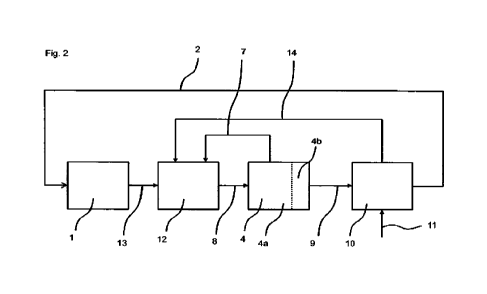
Fig. 2 now shows an arrangement for control and closed-loop control of an
actuating system
of an aircraft according to the disclosure. According to the disclosure, in
comparison to the
17
CA 03158815 2022-5-18
arrangement in Fig. 1, a device 12 for control and closed-loop control of the
actuating system
4 is provided that is configured to receive a reference variable 13 at a first
input interface, which
reference variable 3 indicates a target acceleration at a point of the
aircraft. To this end, the
flight control device 1 is configured to determine the reference variable 13
indicating the target
acceleration from the measured variables 2, and to transmit it to the device
12. At a second
input interface, the device 12 receives a controlled variable 14 that
indicates the actual
acceleration at the point of the aircraft.
In particular, the acceleration of the aircraft can be a local acceleration at
the actuating system
4. Fig. 3 exemplarily shows the arrangement of an acceleration sensor 15 on
the immovable
pad of an elevator 16 of an aircraft. Herein, the elevator 16 is an actuating
system 4 of the
aircraft in which a movement of the flight control surface of a flight control
surface assembly
functioning as the force generator 4a by means of a servomotor as the control
element 4a
exerts a force on the aircraft, which leads to a pitching, and thereby causes
the aircraft to rise
or sink.
Alternatively, the acceleration can be an acceleration at another point of the
aircraft, for
example in a center of gravity of the aircraft. The acceleration can be
measured directly with
an acceleration sensor, or determined from one or several measured values,
which can include
accelerations at one or several other points or other variables than
accelerations, for example
vertical movements (changes in position) of the wings.
The control device 12 determines the control deviation as the difference
between the target
value for the acceleration according to the reference variable 13 and the
actual value for the
acceleration according to the controlled variable 14. An actuating system
reference variable is
determined from the control deviation in the control device 12 through
multiplication by a
proportionality factor, and compared with an actuating system controlled
variable 7, so as to
determine a manipulated variable 8 of the actuating system. Based on the
manipulated
variable 8, the control element 4a produces a positioning of the force
generator 4b that leads
to a force effect 9 on the mechanical system 10 of the aircraft.
In an alternative configuration, such a cascade structure can be replaced by a
parallel
feedback, in which the controlled variables 7 and 14 are fed back, and are
herein each
modified, in particular multiplied by an amplification factor and/or
integrated. The reference
variable 13 is modified according to the controlled variables 7 and 14 by
means of a prefilter,
after which the manipulated variable 8 is determined by adding the controlled
variables 7, 14
and reference variable 13.
18
CA 03158815 2022-5-18
As may be seen in Fig. 2, the controlled variable 14 is a variable of the
mechanical system 10
of the aircraft. The disturbing forces and/or torques 11 influence the
acceleration of the aircraft,
so that the acceleration of the aircraft indicated with the controlled
variable 14 already contains
these influences, at least in part. In comparison to the known concept
illustrated in Fig. 1, the
control concept illustrated in Fig. 2 thus already achieves a consideration of
disturbing forces
and/or torques 11 acting on the aircraft in the control of the actuating
system 4 of the aircraft.
In particular, the manipulated variable 8 can be an actuator voltage or an
actuator current. For
example, the actuating system reference variable can be a target value for a
positioning speed
of the control element 4a, i.e., in particular of an actuator. In this case,
the actuating system
controlled variable 7 can be an actual positioning speed of the control
element 4a. In an
exemplary configuration, a target value for an actuator current is determined
from the
difference between the actuating system reference variable and the actuating
system
controlled variable. The target variable for the actuator current can be the
manipulated variable
8. Alternatively, an additional inner control loop can be provided, in which
the manipulated
variable 8 is determined using the target value of the actuator current.
Fig. 4 shows such a configuration of an arrangement for control and closed-
loop control of an
actuating system of an aircraft, in which another inner control loop is
provided. Exemplarily
shown here is a pitching position control with a rotary, electromagnetic
actuator of an elevator.
As opposed to a known control with feedback of a flight control surface
deflection n, a local
acceleration bzH at the elevator is fed back, and a control deviation to a
specified acceleration
bzH,G is determined within the actuating system control 17. Applying the
factor '<bill, a
proportional positioning speed command ric is determined from the above, which
is set by the
inner speed control loop. The commanded current flow le (actuator reference
variable) results
proportionally (factor K1) from the speed error ric-n, the difference between
the positioning
speed command ne (actuating system reference variable) and the actual
positioning speed
which is the actuating system controlled variable. Finally, the terminal
voltage U of the motor
forms the manipulated variable. It is set proportionally (factor K) to the
control error of the
current control cascade. Herein, the actual current I constitutes the actuator
controlled variable.
Within the framework of the physical processes within the actuator
corresponding to a
modeling as a DC shunt machine, the terminal voltage causes a change in the
current flow in
the motor windings that is anti-proportional to its inductivity L. However,
consideration must be
given to the voltage drop Mires = RI owing to the winding resistance R, as
well as to the
19
CA 03158815 2022-5-18
counter-voltage Allem! = Ke'n induced by the rotational movement proportional
to the motor
constant Ke, which diminish the terminal voltage. The current flow I arises
through integrating
the current change, and produces a drive torque Mact proportional to the motor
constant Kt.
With respect to the physical effect on the actuating system, in addition to
the drive torque Mact,
the aerodynamic rudder hinge moment Macro acts on the flight control surface,
which along
comprises both components proportional to the deflection n with the factor
Cn,aero and damping
components (factor Cri,aero)= In addition, the aerodynamic rudder hinge torque
M i influenced
Macro S
by the direction of inflow (factor Ca,aero)= The resulting overall torque
leads to a positioning
acceleration ri that scales with the inverse 1/J of the rotational inertia.
Shown in the right part of Fig. 4 is a simplified view of the dynamics
underlying the aircraft
pitching movement 18. The pitching acceleration is proportional to the
pitching torque with
the inverse pitching inertia 1/Iyy, which arises from the pitching torque
coefficient through
denormalization with dynamic pressure T1, wing area Sand wing depth 1p. The
latter essentially
comprises influences of the elevator (Cmt,:n), pitching rate (Cmg:Ip:1 /VA: q)
and angle of attack
(Cmc,:a). Apart from the share of elongation 0, the angle of attack a is
determined by the
influence y of the path movement 19. In addition, it contains the main part of
the disturbing
influence (gusts) in the form of the wind adjustment angle aw. The local
acceleration 13,H at the
elevator arises from the pitching acceleration q with the lever rH, as well as
from the vertical
acceleration bz of the aircraft center of gravity.
According to the disclosure, the actuator position is not drawn upon as the
controlled variable,
for example as evident from Fig. 4. No force or torque measurement serves as
the controlled
variable either. In addition, the controlled variable is not measured in the
drivetrain of the
actuator or on the flight control surface, but rather on the assembly
allocated to the flight control
surface (the lift surface immovable relative to the aircraft) in the
embodiment of Fig. 4. No
measurement of the (rotational) acceleration ri of the actuator takes place
that would be
proportional to the positioning torque (drive torque of the actuator, Mad).
Rather, the local
acceleration on the lift surface instead behaves proportionally to the flight
control surface angle
and the lifting force it generates, i.e., to a variable that is separated from
the acceleration ri of
the actuator by two integration steps, as evident in Fig. 4. The local
acceleration is an output
variable which to a substantial extent depends on the flight control surface
angle n as a system
state, and the feedback of which thus enables influencing the system dynamics
in a similar
manner. According to the embodiment shown in Fig. 4, the speed control loop of
a classic
servocontrol (middle cascade in Fig. 4) is to be retained, so that there still
is a continued
CA 03158815 2022-5-18
feedback of a number of linearly independent output variables corresponding to
the system
order. This can make it possible to configure the system dynamics as desired.
As "rigid" a
layout of the rudder angle dynamics as possible may herein be desired. In
particular, reducing
the actuator load or positioning effort might not be the goal; rather, it can
be provided that the
flight control surface be moved as quickly as possible into the position that
compensates for
the influence of gusts on the corresponding flight control surface assembly.
This position is
generally not identical to the resting position, into which the free rudder
would be deflected
with the setting torque held constant.
Local acceleration control can yield advantages over controlling the rudder
hinge torque. The
local acceleration measurement (as opposed to the flight control surface angle
or rudder hinge
torque) directly captures the added lift caused by the gust via the additional
angle of attack ow.
In elastic aircraft, the local accelerations directly reflect the structural
dynamic vibration state.
Feeding the acceleration back to the positioning speed of a flight control
surface acting at the
same location corresponds to a virtual dampening (similar to the so-called
ILAF principle).
Therefore, it can be suitable in particular for actively stabilizing highly
elastic configurations.
Furthermore, the local acceleration includes influences of various flight
state variables (0, y,
q, see Fig. 4), which can also be compensated for by the control. These
influences can become
less important as compared to the highly dynamic feedback path via Kbz,H, so
that a significantly
larger robustness can arise in relation to variable aerodynamic properties. In
a direct, purely
kinematic relation, the local acceleration can be determined from a planned
path and attitude
trajectory. This makes it possible to derive simple pilot control laws, which
are independent of
the properties of a specific aircraft. In this way, the high dynamics of the
local acceleration
control (which correspond to the classic position control loop of the
servocontrol) can be taken
advantage of not just for interference suppression, but also for guidance
behavior. This can
enable a significantly more agile path guidance.
Actuator control (servocontrol) and flight state control (flight control)
represent traditionally
separate research disciplines, which are covered in different expert circles.
The feedback of a
local acceleration measured on the aircraft structure in an inner control
loop, which is
traditionally part of the servo control, builds a bridge between the two
areas. This requires a
holistic examination of the entire controlled system, which interprets the
aircraft and its control
elements as a unit. Using the local acceleration as a default variable makes
it possible to
include pads of the flight dynamic in the controlled system of the
servocontrol. It can become
possible to simplify the controlled system of the flight control, and reduce
dependencies on
specific flight properties, so that classic flight control structures are no
longer applicable.
21
CA 03158815 2022-5-18
According to illustration 4, the boundary for the actuating system control 17
is drawn at local
acceleration bzH and flight control surface deflection n. Other illustrations
are possible, in which
the definitions of subsystems, in particular of the boundaries, are set
differently (e.g., see Fig.
5), without this resulting in a change in the disclosed control principle.
The symbols used in Figures 5, 6 and 7 denote the following variables:
Scalars:
Co: Sliding roll torque
Aileron effectiveness
Op: Roll damping
Actuator current
Ini: Rolling inertia torque
J: Torque of Inertia of the actuator
Kt: Torque constant of the actuator
K...: Controller amplification of the ...-control loop
S: Wing surface
VA: Flight speed
Dynamic pressure
b: Half span
p: Roll rate
P: Shift angle
13w: Wind shift angle
co: Angular velocity of the actuator
4: Aileron deflection
Vectors:
n: Modal amplitudes (structural dynamic degrees of
freedom)
R: Position vector for the local acceleration measuring
point
g: Generalized coordinates
u: Manipulated variables
x: Rigid body degrees of freedom
z: Disturbance variables
Matrices and Tensors:
22
CA 03158815 2022-5-18
Positioning influence on generalized forces of the structural dynamic degrees
of
freedom
Bx: Positioning influence on generalized forces of the
rigid body degrees of freedom
B: Positioning influence on generalized forces
C: Generalized rigidity matrix
D: Generalized damping matrix
Disturbance influence on generalized forces of the structural dynamic degrees
of
freedom
E =
_x. Disturbance influence on generalized forces of the
rigid body degrees of freedom
E Disturbance influence on generalized forces
Fnext, Fiext: Influence of the structural deformation-induced aerodynamic
forces on rigid body
movement
K..: Amplification matrix of the ...-control loop
L: Kinematic translation ratios between generalized rigid body degrees of
freedom and
position of the local acceleration measuring points
M: Generalized inertia matrix
Q1, QTI: Influence of the structure deformation-
induced aerodynamic forces on structural
dynamics
Qx, Qx: Influence of the rigid body movement-
dependent aerodynamic forces on
structural dynamics
A: Eigenforms (eigenvectors) of the structural dynamics
Generalized structural damping factors
Generalized rigidity matrix
g: Modal mass matrix
Indices:
c: Command size, default value, target value
In classic flight control, the command corresponds to the position (angle) of
the aerodynamic
flight control surface. A highly dynamic (rigid) positional control of the
actuator ensures that the
actual flight control surface position precisely follows the positioning
command. The control
structure corresponds to a cascade control with an inner control loop, the
actuator control
(ACL), and an outer control loop, the flight control (FCL). A feedback of
position angles, rotation
rates and speeds takes place. As a rule, acceleration measurements are only
used for
observation or as a replacement for poorly measurable states.
23
CA 03158815 2022-5-18
Also known is a rudder hinge torque-based flight control. The command for the
FCL
corresponds to a torque specification, meaning a direct current specification,
for the actuator.
In a state of equilibrium, the torque specification corresponds to the
aerodynamic rudder hinge
torque. The concept is similar to the force-oriented control behavior of the
pilot during manual
control. This type of control is supposed to offer advantages with respect to
flight silence and
load reduction, since the control surface deviates owing to an altered hinge
torque of the gust.
This is intended to reduce an actuator load and force fight in the case of
redundant actuators.
A local linearization and inversion of the system dynamics takes place in the
likewise previously
known incremental nonlinear inversion (IND!). Incremental growths in the
positioning
command are calculated. The method is based on measured and commanded
(rotational)
accelerations, and reduces the influence of the (aerodynamic) model accuracy
and center of
gravity for elevated robustness. The positioning law is herein based upon the
comparison
between planned and actual changes (and thus, derivations) of the state
variables, which are
calculated or observed based on rotatory and translatory acceleration
measurements. As
opposed to the concepts disclosed herein, a direct use of this change in
positional variable in
an inner cascade of the servocontrol or an expansion of the INDI approach to
the actuator
dynamics is not known for this approach. In a proposed approach, the actuator
current serves
as a given variable, and a positioning law modified for this purpose is
derived. As opposed to
the approach according to the present disclosure, the quasi-stationary
dependence of the
actuator current on the rudder hinge torque is taken as the basis, so that the
dynamics of the
actuating system themselves remain unregulated.
Feeding back acceleration measurements or modal degrees of freedom is known
for an active
flutter control and load reduction. Herein, the command corresponds to the
flight control
surface position. Alternatively, additional forces are applied by vibration
actuators. This often
does not take place in terms of closed-loop control, but specifically to
compensate for individual
resonance frequencies.
In the known systems, the dynamics (bandwidth) of the flight controller to a
large extent
determine the precision of path and position maintenance (interference
suppression), flight
silence (interference suppression), and agility of path guidance (guidance
behavior). The
maximum bandwidth is limited by the dynamics of the independently configured
actuator
control (inner control loop), and possibly also by the dynamics of the
mechanical transmission
path between the actuator and flight control surface, the structural dynamics
of an elastic
aircraft, and the transient aerodynamics. A precise aerodynamic model is
required for an
optimal FCL configuration. This is costly and can be associated with a lack of
robustness. The
24
CA 03158815 2022-5-18
inner control loops, at least the position control, must be individually
designed for each aircraft
type. A precise aeroelastic model is required to preclude excitations of the
structural dynamics.
Having the flap deflection rik act directly on the vertical load multiple
(i.e., the load acceleration)
nz complicates the design of a gust load control. Abatement potential is
limited without the
provision of a pilot control, which is accompanied by a complex angle of
attack measurement.
Fig. 5 shows a schematic illustration of a concept for an acceleration-based
rolling position
control of an aircraft. In comparison to the known system, the position
control of the actuators
is replaced by the feedback of an acceleration measurement, which determines
the
aerodynamic force effect of the flight control surface (for example, local
acceleration at the
flight control surface or rotational acceleration of the aircraft). The
classic division between
actuator control and flight control is altered herein. The interface between
FCL and actuator
control slides inwardly by one cascade. The state feedback of the actuator
deflection is
replaced by an output feedback of the acceleration proportional thereto, which
additionally
contains the interference influence (gusts). The command of the FCL then
corresponds to the
positioning rate (angular velocity) of the flight control surface. A
measurement of the flight
control surface position is only required to consider the positional limit.
In the case of an aircraft, the controlled system of the FCL, the rolling
torque coefficient 0 is
proportional to the aileron deflection 4, which in known systems constitutes
the manipulated
variable, with the factor C. The rolling torque coefficient 0 p is
proportional, with the factor CI,
to the shift angle p, which is construed as a disturbance variable for pure
rolling control, and in
particular incorporates the wind influence I3w. The rolling torque coefficient
CI is proportional,
with the factor Cip, to the dimensionless rolling rate p*=p.b/VA. The rolling
torque follows from
the coefficient CI through multiplication by the reference variables (4, S,
b), with the rolling
acceleration also being proportional to the inverse rolling inertia (1/Iyy).
The rolling rate p and
rolling angle Ã13 arise through integration from the rolling acceleration.
Known flight control
comprises the complete feedback of the states "rolling rate (p)" and
"suspension angle (0)".
Herein, the system is set up in the form of a cascade control, in which the
outer control loop
comprises the rolling position with the reference variable "rolling command
((D)" and
manipulated variable "rolling rate command (pc)", which with amplification Ka,
is proportional to
the control error (13c - W. The inner control loop then relates to the rolling
rate with the reference
variable "rolling rate command (pc)" and manipulated variable "aileron command
(c)", which
with the amplification Kp is proportional to the control error pc ¨ p.
25
CA 03158815 2022-5-18
For the actuator, the control system ACL, the actual current flow I
corresponds to the current
command lc when disregarding the electrical time constant. The torque with
torque constant Kt
is proportional to the current flow. Additional torque coefficients (friction,
aerodynamic rudder
hinge torque, etc.) are disregarded. The rotational acceleration (ud ) of the
downforce follows
from the conservation of angular momentum as the torque/inertia torque (J).
The positioning
speed (w) and downdraft angle (which corresponds to the aileron deflection
follow through
integration of the rotational acceleration. Known actuator control then
involves the complete
feedback of the states "positioning speed (w)" and "actuator position (0". The
system is set up
in the form of a cascade control, in which the outer control loop comprises
the actuator position
with the reference variable "aileron command ()" and manipulated variable
"setting rate
command (coc)", which with the amplification KE. is proportional to the
control error - 4. The
inner control loop then relates to the positioning speed with the reference
variable "setting rate
command (ific)" and manipulated variable "current command (lc)", which with
the amplification
Km is proportional to the control error ific - cu.
By comparison to the above, Fig. 5 shows an acceleration-controlled concept
with the
controlled system aircraft 20, the actuator 21 and the controlled system
actuator 22. The
measured rolling acceleration (p) is fed back instead of the aileron
deflection (4) proportional
thereto. The command We of the FCL corresponds to the positioning rate 4.
Apart from the flight
control surface position 4, the disclosed feedback also directly acquires the
interference
influence through 13 orl3w. As a consequence, the disturbance is already
compensated for one
control loop further in than for known flight control. Given a highly dynamic
configuration of this
acceleration control loop (p-feedback), significantly better interference
suppression can be
achieved. The default value for the position control loops (traditional "inner
loops" of the FCL)
corresponds directly to the rate acceleration (second derivation of the
controlled variable).
Given a highly dynamic configuration of acceleration control, the aircraft
directly follows the
specified rate acceleration (pc p). This yields a simple, linear behavior
independent of aircraft-
specific parameters. The configuration of position control can be
standardized, and can take
place independently of the aircraft type and flight status. Given a highly
dynamic configuration,
the acceleration feedback via Kp = CIE. becomes dominant relative to the
remaining aerodynamic
influences (via Co and Op), whereby the influence of aerodynamic parameters
(other than CO
on the control circuit is reduced. This makes it possible to forego a precise
aerodynamic model
for the FCL configuration. Only the rudder effectiveness Clz, and dynamic
pressure remain
relevant. Preventing the positioning command from acting directly on the
acceleration
measurement simplifies the configuration and elevates the potential of control-
based gust load
reduction.
26
CA 03158815 2022-5-18
For rigid aircraft, the principle can be transferred to the pitching degree of
freedom (measured
variable: pitching acceleration, primary manipulated variable: elevator), the
yaw degree of
freedom (measured variable: yaw acceleration, primary manipulated variable:
rudder), lift
degree of freedom (measured variable: vertical acceleration nz, primary
manipulated variable:
flap), longitudinal degree of freedom (measured variable: longitudinal
acceleration nx, primary
manipulated variable: spoiler), as well as transverse degree of freedom (only
for lateral force
control). The acceleration component is ideally fed back not just to the
primary manipulated
variable, but to all manipulated variables that influence the respective
degree of freedom, for
example via the aileron rolling torque, rudder yaw torque, elevator lift or
flap pitching torque.
The degrees of freedom can be completely decoupled by suitable selection of
the amplification
matrix. The described degrees of freedom, the acceleration of which is
measured, can be
chosen as desired. For example, the rotation and translation of the center of
gravity is named
in aircraft-fixed coordinates. Likewise conceivable are other coordinate
systems, as well as
other (possibly even several) reference points of the rigid body, for example
the vertical
position of both wing tips instead of the rolling angle. Any combination of
independent degrees
of freedom that clearly describes the system is possible. The latter
constitutes a valid set of
generalized coordinates (q) in the sense of Lagrange formalism.
Based on a schematic illustration of a concept for an acceleration-based
control, Fig. 6 shows
the transferability of the disclosed control concept to general mechanical
systems. The
principle can be transferred to any mechanical system 23 with n degrees of
freedom, which
can be clearly described by generalized coordinates in terms of Lagrange
formalism, which is
controlled by one or several manipulated variables that exert a direct force
or torque influence
on the system 23, and the manipulated variables of which are operated by a
controlled actuator
24 with at least simple integrating behavior (all mechanical actuators).
Given an actuator position-controlled approach, as opposed to the system
according to Fig. 6,
the manipulated variable u, has a force influence that can be described by
generalized forces
Q =B,j(,g).ul. The same holds true for force or torque disturbances z, with
impact factors
The acceleration 0; of the generalized coordinate is proportional with M1(g)
to the
generalized force Q. Generalized speeds g and coordinates g follow through
integration.
Generalized speeds g produce non-conservative "damping forces" D(g,g)= g in
dissipative
systems. Conservative forces are proportional with C(g) to generalized
coordinates g. In
known control concepts, all states are completely fed back, represented by the
generalized
coordinates (g) and speeds (g). Buildup takes places in the form of a cascade
control, wherein
the outer control loop relates to generalized coordinates. Their reference
variable comprises
27
CA 03158815 2022-5-18
the target values of the generalized coordinates (gc). The manipulated
variable consists of the
target values for the generalized speeds (gc), which are proportional with the
amplification
matrix (Kg) to the control error gc ¨ g. The inner control loop relates to
generalized speeds,
wherein the reference variable comprises target values for the generalized
speeds (pc), and
the manipulated variable comprises positioning commands (u,), which are
proportional to the
control error crc - cf with the amplification matrix Kg .
The actuator has an arbitrary transfer behavior G(s) between the commanded and
actual
change in the manipulated variable 0, but at least one integration stage.
Actuator control
comprises the feedback of (at least) manipulated variables u, wherein the
reference variable
is the target value for the system manipulated variables tic. The actuator
manipulated variable
is the target value for the system positioning rates 0c, which is proportional
to the control error
uc ¨ u with amplifications K.
By comparison to known controls, the measured, generalized accelerations g are
fed back in
the acceleration-controlled approach according to Fig. 6 instead of the
manipulated variables
u proportional thereto. The control command corresponds to the setting rate J.
Fig. 7 illustrates a concept for an acceleration-based control of elastic
aircraft. Fig. 7 here
shows the general case of a complete state feedback. An elastic aircraft
constitutes a special
case of the disclosed concept explained in connection with Fig. 6, since it
can be described by
Lagrange formalism. In principle, generalized coordinates can be selected as
desired. One
possibility involves individual positions of acceleration sensors distributed
over the aircraft. The
measured acceleration herein corresponds directly to the generalized
acceleration ql This
requires at least six sensors for acquiring the rigid body movement. The
number of additional
sensors determines how many elastic modes can be acquired. An alternative
option involves
a separation of rigid body movement (mean axes) and structural dynamics.
Herein, a division
takes places into rigid body degrees of freedom (x = [x, y, z, (D, 0,T1) and
amplitudes (n
mil) of the elastic modes, so that g = [x,, if. The movement equations for the
rigid body
movement and structural dynamics are inertially decoupled, but a coupling by
way of outside
forces (aerodynamics) does exist.
The controlled system comprises the rigid body dynamics (below in Fig. 7),
which is built up
similarly to the system in Fig. 6, wherein the correlations g = x, = B, and E
= Ex apply. With
respect to structural dynamics (above in Fig. 7), the manipulated variable u,
has a force
influence that can be described by generalized forces Qj
13,1,1(4, g). The same applies to
28
CA 03158815 2022-5-18
force and torque disturbances (z,) with the impact factors Eii,,j(q., g). The
second derivation of
the modal amplitude rjr is proportional to the generalized force q with the
inverse modal mass
matrix 111(ij). The structural damping produces damping forces, which are
proportional to the
rate of change in the modal amplitudes with
damping factors Z. The structural elasticity
produces spring forces that are proportional to the modal amplitudes with the
generalized
rigidity matrix y.
Outside forces produce a coupling between the structure movement and rigid
body movement.
Herein, the outside forces (aerodynamic forces/torques) depend on rigid body
states and x
and structural dynamic states n' and n. Outside forces influence both the
rigid body movement
(R) and the structural dynamics (0). The portion of the forces on the rigid
body movement
dependent on rigid body movement was already considered by D, C. The influence
of the
structural deformation-induced portion of forces on the structural dynamics
(Qii and Qif) is (by
contrast) not already contained in D, y. The dependence of forces on rigid
body movement
yields an influence on the structural dynamics: Qx, Q. The outer control loops
relate to the
generalized coordinates (g = [x,, TOT), the inner control loops to the local
degrees of freedom
(Rf). The system behavior depends on the description form (transformation
between various
degrees of freedom systems/state illustrations).
A specific case of the concept according to Fig. 7 relates to a local
acceleration feedback.
Herein, the acceleration is measured directly at the location of the flight
control surface. The
feedback matrix KR is only diagonally occupied, meaning that the acceleration
acts exclusively
on the flight control surface where the measurement takes place. The system
dynamics can
be freely specified, provided the number of setting/measuring positions
corresponds to the
number of (considered) degrees of freedom (and have been suitably selected,
i.e., are linearly
independent; this leads to controllability and observability). By contrast,
providing a complete
eigenstructure is not possible. The system remains coupled. Assuming that the
positioning rate
command is converted without any delay (disregarding the actuator dynamics),
the feedback
of acceleration to the positioning rate is equivalent to the feedback of the
speed to the actuator
position. Assuming that the aerodynamic force generation by the flight control
surface takes
place without any delay (disregarding transient aerodynamics), a speed-
proportional
counterforce is generated. The acceleration feedback thus corresponds to a
virtual, viscous
damper that acts at the location of the flight control surface. Introducing an
integrating part or
feeding back a local speed measurement would similarly allow introducing a
virtual spring
element, thereby yielding a more or less rigid clamping of the wing at the
location of the flight
control surface. Because the damping force always counteracts the direction of
movement, an
energy supply, and hence a destabilization of the structural dynamic modes is
precluded.
29
CA 03158815 2022-5-18
However, this only applies for as long as the assumptions are justified, i.e.,
for all structural
modes that are clearly lower frequency than the actuator dynamics/transient
aerodynamics.
This limits the maximum realizable dynamics for acceleration feedback.
By contrast, the risk of an excitation exists in an acceleration measurement
that is locally
separate from the flight control surface (e.g., IMU in the cockpit), since the
acceleration signal
only reacts to the force generated on the flight control surface after a delay
caused by the
structural dynamics. Expressed differently, an eigenform can possibly exist
the vibration
antinode of which, at the measurement location, has an opposite sign compared
to the location
of the force generation (flight control surface). A negative, destabilizing
damping force thus
arises in the frequency range of this eigen mode. This is precluded if the
measurement takes
place directly at the location of force generation.
In classic flight control, the bandwidth limitation arises from the frequency
separation to the
structural dynamics. By contrast, a bandwidth limitation arises for the local
acceleration
feedback from the frequency separation to transient aerodynamics and actuator
dynamics.
In particular, advantages of the acceleration-controlled concept can lie in
the achievability of a
higher dynamic for flight control, and hence improved interference
suppression, flight silence
and higher agility, especially in the case of highly elastic aircraft, wherein
no frequency
separation to the structural dynamics or filtering of elastic modes is
required. An automatic
damping of all elastic modes below the actuator dynamics and in particular the
aerodynamics
can be enabled, independently of the concrete elastic properties of the
aircraft. Interference
influences (local gusts) are balanced out directly at the attack site, without
exciting the
structural dynamics (similar to a bird that only locally spreads feathers to
yield to a gust).
Structural loads are reduced. The acceleration measurement and control can be
integrated
into an actuator control (smart actuator). This enables a decentralized system
structure. The
acceleration-regulated concept permits new redundancy concepts and allows a
simple
adaption of control laws in the event of a flight control surface failure.
Given a sufficient
frequency separation between the acceleration control (decentralized in the
actuator) and
position control (centrally in the FCC), the position control and all higher-
level control loops
can remain unchanged, since the reduced dynamics of acceleration control are
still fast
enough. This reflects the fact that, in classic flight control, the failure of
a redundant actuator
for the same flight control surface as a rule requires no adaption of the FCL.
Figures 8A to 8E show the overall system dynamics in the complex plane of an
exemplary
embodiment of the arrangement, which can arise from transferring the structure
illustrated in
CA 03158815 2022-5-18
Fig. 5 to the pitch degree of freedom. Fig. 8B here shows a magnified cutout
of Fig. 8A, Fig.
8C a magnified section of Fig. 8B, Fig. 8D a magnified section of Fig. 8C, and
Fig. 8E a
magnified section of Fig. 8D. The illustration in Figures 8A to 8E is based
upon a device for
controlling the elevator as per the present disclosure. The longitudinal
position U and pitch rate
q are fed back. The pole and zero position distribution is shown, which for
the depicted
embodiment arises for various feedback amplifications (+-shaped markings).
Also shown for
comparison is the pole and zero position distribution that arises for a
previously known control,
in which the adjustment angle of the elevator is controlled by the actuating
system control (x-
shaped markings). The magnified x- or +-markings denote the pole positions
that arise when
both feedback amplifications (for q and A) assume the value zero. For the
previously known
control (x), this pole distribution corresponds to a pattern known for
uncontrolled aircraft, in
which one conjugated complex pole pair is to be allocated to the phygoid
movement and
another to the angle of attack vibration. Feeding back the local acceleration
within the
framework of the disclosed embodiment, the angle of attack vibration is
strongly dampened
and split into two real poles. By contrast, this has hardly any influence on
the phygoid poles.
The depicted smaller markings connected by lines denote pole positions that
can arise given
a simultaneous increase in feedback amplifications for the pitch rate and
longitudinal position
in a constant ratio. The star-shaped markings denote pole positions that can
arise for an
advantageous selection of feedback amplifications when a high bandwidth for
the control
circuit is desired at a damping level that does not drop below the value 0.7.
Fig. 9 shows a Bode diagram for a previously known 25 and for the disclosed 26
embodiment
according to Figures 8A to 8E, which can arise for a respectively advantageous
selection of
feedback amplifications. Shown is the frequency response of an interference
transmission
function of the vertical wind speed wwg (gust) on the longitudinal position O.
In a frequency
range below the dynamic of the actuating system control, the disclosed
embodiment 26 (solid
line) reveals an improved interference behavior, since the transmission
function of the
previously known arrangement 25 (broken line) has an additional zero point,
which nearly
compensates for the pole associated with the position control loop of the
servocontrol. This
zero point is eliminated by the acceleration feedback.
Fig. 10 illustrates an exemplary embodiment for a flexible aircraft. Without
placing any limitation
on generality, the view in Fig. 11 is herein limited to the flexibility of the
main wing in relation
to a bending around the longitudinal axis, a torsion around the transverse
axis, as well as the
resultant local vertical movements. In addition to the six degrees of freedom
of a rigid body, a
31
CA 03158815 2022-5-18
flexible aircraft has additional degrees of freedom, which describe the
deformation state. Apart
from the rigid body degrees of freedom of an undeformed reference
configuration 27, a
conventional presentation form comprises the amplitudes of superposed
eigenforms of the
elastic modes, which describe characteristic deformation patterns as compared
to the
reference configuration. Such an eigenform is exemplarily depicted in Fig. 10.
Herein, the
eigenform can have local extreme points 28, at which the deviations from the
reference
configuration are greatest, and node points 29, at which the deviations from
the reference
configuration disappear. In order to control and stabilize the deformation
degrees of freedom,
a flexible aircraft can have several actuating systems (flight control surface
assemblies), which
can be comprised of flight control surfaces 30 and possibly fins 31. A device
according to the
present disclosure can use one or several actual accelerations at any points
32 of the aircraft
for control purposes. In an advantageous embodiment, for example, these can be
extreme
points or node points of one or several eigenforms, but also points at which
none of the
eigenforms relevant for control purposes has a node point. In particular, the
number of used
accelerations can correspond to a number of eigenvalues that are to be
stabilized or influenced
by the control. For example, all accelerations can herein be received by each
of the provided
devices. Alternatively, a device can only receive those accelerations that can
be influenced by
an adjustment of the actuating system controlled by the device.
Shown in Fig. 11 is a design of an arrangement for a flexible aircraft, in
which the points 32 of
the aircraft where the local acceleration is used for controlling the
actuating systems lie in
proximity to the flight control surfaces 30. For example, all accelerations
can herein once again
be received by all disclosed devices. Alternatively, each device can receive
only the respective
acceleration that is present in proximity to the actuating system controlled
by this device.
The features disclosed in the above specification, the claims and the drawing
can be important
both individually and in any combination for implementing the different
embodiments.
32
CA 03158815 2022-5-18