Note: Descriptions are shown in the official language in which they were submitted.
WO 2021/102117
PCT/US2020/061245
SEALING OF AN ELECTRONIC LOCK
100011 This application claims the benefit of
U.S. Provisional Application Serial
No. 62/939,406, filed November 22, 2019; and U.S. Provisional Application
Serial
No. 63/069,888, filed August 25, 2020, the disclosures of which are hereby
incorporated
by reference in their entireties.
Backaround
100021 Weather conditions can damage an
electronic lock, specifically any
electronics and the wiring harness. Therefore, the electronic lock can become
inoperable if
improperly protected from the weather. Further, the electronic lock needs to
withstand
regular user input while remaining sealed to the elements.
100031 Typical electronic door locks require a
wiring harness to pass from the
exterior of the mounted-to door to the interior of the mounted-to door. Wired
communication between the exterior and interior of the lock is often required
for the
unlocking and locking function. This is due to the fact that both a power
source and a
processor are typically mounted within the interior portion of the electronic
door lock.
Accidental disconnection of the wiring harness from either the interior or
exterior
assembly of the lock prevents the assemblies from communicating, therefore
rendering the
electronic lock inoperable.
100041 Therefore, improvements are desired.
Summary
100051 The present disclosure is directed to an
electronic lock. In certain examples,
aspects of the present disclosure relate specifically to sealing of an
electronic lock.
100061 One aspect of the present disclosure
relates to an electronic lock. The
electronic lock includes an exterior assembly and an interior assembly. The
electronic lock
includes a wiring harness connectable to the exterior and interior assemblies
to allow
communication therebetween. The wiring harness includes a seal therearound.
The
exterior assembly includes a wiring harness electrical receptacle that is
configured to
connect to the wiring harness having a first orientation. The exterior
assembly includes a
wiring harness receiving port that is aligned with the wiring harness
electrical receptacle.
The wiring harness receiving port includes a first portion sized and shaped to
position the
seal of the wiring harness between walls of the first portion and the wiring
harness. The
wiring harness receiving port includes a second portion that includes port
bathers sized
1
CA 03158971 2022-5-19
WO 2021/102117
PCT/US2020/061245
and shaped to allow for the wiring harness to pass through the second portion
when the
wiring harness is in a first orientation. The port barriers of the second
portion limit axial
movement of the wiring harness through the second portion when the wiring
harness is in
a second orientation.
100071 Another aspect of the present disclosure
relates to a mounting plate for use
in an electronic lock. The mounting plate includes a main body and a wiring
harness
electrical receptacle configured to connect to a wiring harness. The mounting
plate
includes a wiring harness receiving port that is defined in the main body and
axially
aligned with the wiring harness electrical receptacle. The wiring harness
receiving port
includes a first portion sized and shaped to seal around the wiring harness
and a second
portion sized and shaped to axially limit the movement of the wiring harness
therein.
100081 Another aspect of the present disclosure
relates to another electronic lock.
The electronic lock includes an exterior assembly positioned at an exterior of
a door. The
electronic lock includes an interior assembly that has a power source and a
processor. The
electronic lock includes a bolt movable between an extended position and a
retracted
position, wherein the exterior assembly and the interior assembly are
connected to, and
capable of actuating, the bolt. The electronic lock includes a wiring harness
that is
connectable to the exterior and interior assemblies to allow communication
therebetween.
The exterior assembly includes a first authentication source to selectively
actuate the bolt.
The first authentication source is a biometric fingerprint sensor. The
biometric fingerprint
sensor is connected to the processor of the interior assembly via the wiring
harness to
selectively actuate the bolt when a valid credential is received at the
biometric fingerprint
sensor The exterior assembly includes a second authentication source that is
at least one
of a mechanical lock, a keypad, a touch surface, and a NFC reader.
100091 Another aspect of the present disclosure
relates to another electronic lock.
The electronic lock includes an exterior assembly that is configured to be
positioned at an
exterior of a door. The electronic lock includes an interior assembly that is
configured to
be positioned at an interior of a door. The interior assembly has a power
source and a
processor. The electronic lock includes a bolt movable between an extended
position and a
retracted position. The exterior and interior assemblies are connected to, and
capable of
actuating, the bolt. The exterior assembly includes an escutcheon mated to a
main body
and a sensor to selectively actuate movement of the bolt when a valid
credential is
received at the sensor. The sensor has a first side and an opposite second
side, and the first
side is accessible from the escutcheon, and the sensor is in communication
with, and
2
CA 03158971 2022-5-19
WO 2021/102117
PCT/US2020/061245
connected to, the processor of the interior assembly. The exterior assembly
includes a first
seal positioned around the sensor at the first side between the sensor and the
escutcheon.
The exterior assembly includes a retainer that is positioned at the second
side of the sensor
to position the sensor immediately adjacent the escutcheon. The exterior
assembly
includes a second seal positioned between the second side of the sensor and
the retainer.
[0010] Another aspect of the present disclosure
relates to another electronic lock
The electronic lock includes an exterior assembly that is configured to be
positioned at an
exterior of a door. The electronic lock includes an interior assembly that is
configured to
be positioned at an interior of a door. The interior assembly has a power
source and a
processor. The electronic lock includes a bolt movable between an extended
position and a
retracted position. The exterior and interior assemblies are connected to, and
capable of
actuating, the bolt. The exterior assembly includes an escutcheon mated to a
main body
and a sensor to selectively actuate movement of the bolt when a valid
credential is
received at the sensor. The sensor has a first side and an opposite second
side, and the first
side is accessible from the escutcheon. The sensor is in communication with,
and
connected to, the processor of the interior assembly. The exterior assembly
includes a
retainer that is positioned at the second side of the sensor to position the
sensor
immediately adjacent the escutcheon. The exterior assembly includes a light
source that is
positioned at the second side of the sensor. The light source is configured to
indicate an
operational status of the electronic lock. The exterior assembly includes a
light source seal
positioned at the first side of the sensor between the sensor and the
escutcheon and also
positioned around the retainer. The light source seal is accessible from the
escutcheon, and
the light source seal is configured to display light from the light source at
the first side of
the sensor.
[0011] A variety of additional aspects will be
set forth in the description that
follows. The aspects can relate to individual features and to combinations of
features. It is
to be understood that both the foregoing general description and the following
detailed
description are exemplary and explanatory only and are not restrictive of the
broad
inventive concepts upon which the embodiments disclosed herein are based.
Brief Description of the Drawins
[0012] The following drawings are illustrative
of particular embodiments of the
present disclosure and therefore do not limit the scope of the present
disclosure. The
drawings are not to scale and are intended for use in conjunction with the
explanations in
the following detailed description. Embodiments of the present disclosure will
hereinafter
3
CA 03158971 2022-5-19
WO 2021/102117
PC171.15.2020/061245
be described in conjunction with the appended drawings, wherein like numerals
denote
like elements.
[0013] FIG. 1 is a perspective view of an
electronic lock, according to one
example of the present disclosure.
[0014] FIG. 2 is a perspective view of the
electronic lock of FIG. 1 installed on a
door.
[0015] FIG. 3 is an interior perspective view
of the electronic lock of FIG. 1
installed on a door.
[0016] FIG. 4 is an exterior perspective view
of the electronic lock of FIG. 1
installed on a door.
[0017] FIG. 5 is a schematic of the electronic
lock of FIG. 1.
[0018] FIG. 6 is a front perspective view of an
exterior assembly of the electronic
lock of FIG. 1.
[0019] FIG. 7 is a rear perspective view of the
exterior assembly of FIG. 6.
[0020] FIG. 8 is a front exploded view of the
exterior assembly of FIG. 6.
[0021] FIG. 9 is a rear exploded view of the
exterior assembly of FIG. 6.
[0022] FIG. 10 is a front perspective view of
the exterior assembly of the
electronic lock of FIG. 1. with an escutcheon removed.
[0023] FIG. 11 is a perspective view of a
wiring harness, according to one example
of the present disclosure.
[0024] FIG. 12 is a schematic section view of a
portion of the exterior assembly of
FIG. 6.
[0025] FIG. 13 is a front view of a port of a
mounting plate of the exterior
assembly of the electronic lock of FIG. 1.
[0026] FIG. 14 is a rear view of the port of
FIG. 13.
[0027] FIG. 15 is a front view of the port of
FIG. 13 with a wiring harness
positioned in a first orientation therein.
[0028] FIG. 16 is a front view of the port of
FIG. 13 with the wiring harness
positioned in a second orientation therein.
[0029] FIG. 17 is a schematic section view of
the electronic lock of FIG. 1
installed on a door.
[0030] FIG. 18 is a front perspective exploded
view of the exterior assembly of the
electronic lock of FIG. 1.
[0031] FIG. 19 is a rear perspective exploded
view of the electronic lock of FIG. 1.
4
CA 03158971 2022-5-19
WO 2021/102117
PCT/US2020/061245
[0032] FIG. 20 is a section view along line 20-
20 of the electronic lock in FIG. 17.
100331 FIG. 21 is a perspective section view of
the electronic lock of FIG. 20.
100341 FIG. 22 is a front perspective exploded
view of an exterior assembly of an
electronic lock, according to one example of the present disclosure.
100351 FIG. 23 is a section view of the
electronic lock of FIG. 22.
100361 FIG. 24 is a perspective section view of
the electronic lock of FIG. 20.
100371 FIG. 25 is another perspective section
view of the electronic lock of
FIG. 20.
[0038] FIG. 26 is a front view of a portion of
the electronic lock of FIG. 20.
Detailed Description
[0039] Various embodiments will be described in
detail with reference to the
drawings, wherein like reference numerals represent like parts and assemblies
throughout
the several views. Reference to various embodiments does not limit the scope
of the
claims attached hereto. Additionally, any examples set forth in this
specification are not
intended to be limiting and merely set forth some of the many possible
embodiments for
the appended claims.
[0040] This disclosure generally relates to an
electromechanical lock with certain
features. The term "electronic lock" is broadly intended to include any type
of lockset that
uses electrical power in some manner, including but not limited to, electronic
deadbolts,
electronic lever sets, etc. This disclosure encompasses the integration of one
or more
features described herein into any type of electronic lock and is not intended
to be limited
to any particular type of electronic lock.
[0041] Further, this disclosure relates
generally to a biometric electronic lock that,
based on the biometric data received, is configured to perform a plurality of
operations.
Biometric data may be fingerprint data, which is used as an example
throughout, although
other types of biometric data are contemplated. In an example embodiment, if
the
biometric data received, for example fingerprint data, is a known and
authorized user, the
electronic lock actuates the locking bolt to unlock the electronic lock. If
the fingerprint
data received is not a known user, the electronic lock does not actuate the
locking bolt.
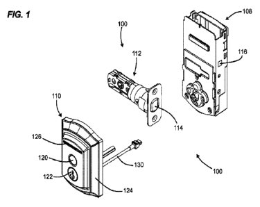
[0042] FIG I. shows an electronic lock 100,
according to one example of the
present disclosure. FIGS. 2-5 illustrate the electronic lock 100 mounted to a
door 102. The
electronic lock 100 includes an interior assembly 108, an exterior assembly
110, and a
latch assembly 112. The door has an interior side 104 and an exterior side
106_
CA 03158971 2022-5-19
WO 2021/102117
PCT/US2020/061245
100431 In some examples, the interior assembly
108 is mounted to the interior side
104 of the door 102, and the exterior assembly 110 is mounted to the exterior
side 106 of
the door 102. The latch assembly 112 is typically at least partially mounted
in a bore
formed in the door 102. The term "outside" is broadly used to mean an area
outside the
door 102 and "inside" is broadly used to denote an area inside the door 102.
With an
exterior entry door, for example, the exterior assembly 110 may be mounted
outside a
building, while the interior assembly 108 may be mounted inside a building.
With an
interior door, the exterior assembly 110 may be mounted inside a building, but
outside a
room secured by the lock 100, and the interior assembly 108 may be mounted
inside the
secured room. The lock 100 is applicable to both interior and exterior doors.
100441 The interior assembly 108 can include a
processing unit 116 (shown
schematically) containing electronic circuitry for the electronic lock 100. In
some
examples, the interior assembly 108 includes a manual tumpiece 118 that can be
used on
the interior side 104 of door 102 to move a bolt 114 between the extended and
retracted
positions.
100451 The latch assembly 112 is shown to
include the bolt 114 that is movable
between an extended position (locked) and a retracted position (unlocked,
shown in FIGS.
1-3). Specifically, the bolt 114 is configured to slide longitudinally and,
when the bolt 114
is retracted, the door 102 is in an unlocked state. When the bolt 114 is
extended, the bolt
114 protrudes from the door 102 into a door jamb (not shown) to place the door
in a
locked state.
100461 The processing unit 116 is operable to
execute a plurality of software
instructions (i.e., firmware) that, when executed by the processing unit 116,
cause the
electronic lock 100 to implement the methods and otherwise operate and have
functionality as described herein. The processing unit 116 may comprise a
device
commonly referred to as a microprocessor, central processing unit (CPU),
digital signal
processor (DSP), or other similar device and may be embodied as a standalone
unit or as a
device shared with components of the electronic lock 100. The processing unit
116 may
include memory for storing the software instructions, or the electronic lock
100 may
further comprise a separate memory device for storing the software
instructions that is
electrically connected to the processing unit 116 for the bi-directional
communication of
the instructions, data, and signals therebetween.
100471 In some examples, the electronic lock
100 can wirelessly communicate
with external devices through a desired wireless communications protocol. In
some
6
CA 03158971 2022-5-19
WO 2021/102117
PCT/US2020/061245
examples, an external device can wirelessly control the operation of the
electronic lock
100, such as operation of the bolt 114. The electronic lock 100 can utilize
wireless
protocols including, but not limited to, the IEEE 802.11 standard (Wi-E), the
IEEE
802.154 standard (Zigbee and Z-wave), the IEEE 802.15.1 standard (Bluetooth ),
a
cellular network, a wireless local area network, near-field communication
protocol, and/or
other network protocols. In some examples, the electronic lock 100 can
wirelessly
communicate with networked and/or distributed computing systems, such as may
be
present in a cloud-computing environment.
100481 The exterior assembly 110 includes a
first authentication source 120, a
second authentication source 122, and escutcheon 124. In some examples, the
exterior
assembly 110 includes only one authentication source. In some examples, the
exterior
assembly 110 includes more than the first and second authentication sources
120, 122. In
some examples, the exterior assembly 110 includes a light source 126.
100491 The first authentication source 120 is
shown to be exposed at the exterior
assembly 110, through the escutcheon 124. The first authentication source 120
is shown to
be a biometric sensor, such as a fingerprint sensor. In some examples, the
fingerprint
sensor is configured to capture an image of a least a portion of a fingerprint
placed
thereon. The biometric sensor can utilize optical, capacitance, thermal,
pressure, low radio
frequency, and/or ultrasonic technology to capture the image of the
fingerprint. In
addition, the biometric sensor can be configured to utilize a static sensor or
a moving
sensor. In some examples, the biometric sensor is configured to allow a finger
to be
swiped over the biometric sensor. In some examples, software can be utilized
that takes a
complete snapshot of the finger.
100501 The second authentication source 122 is
shown to be exposed at the
exterior assembly 110. The second authentication source 122 can be at least
one of at least
one of a mechanical lock, a keypad, a touch surface, a NFC reader, and/or the
like. In the
depicted example, the second authentication source 122 is a keyway for a
mechanical lock.
If the second authentication source 122 is a keypad, the keypad can be one of
a numeric
keypad, an alpha keypad, and/or an alphanumeric keypad. The keypad can have a
plurality
of characters displayed thereon. For example, the keypad can include a
plurality of buttons
that can be mechanically actuated by the user (e.g., physically pressed). In
some examples,
the keypad includes a touch interface, such as a touch screen or a touch
keypad, for
receiving a user input. The touch interface is configured to detect a user's
"press of a
button" by contact without the need for pressure or mechanical actuation. An
example of
7
CA 03158971 2022-5-19
WO 2021/102117
PCT/US2020/061245
the touch interface is described in U.S. Patent No, 9,424,700 for an
"ELECTRONIC
LOCK HAVING USAGE AND WEAR LEVELING OF A TOUCH SURFACE
'THROUGH RANDOMIZED CODE ENTRY," which is hereby incorporated by reference
in its entirety.
100511 In further examples, the electronic lock
100 includes other types of touch
activation capability. In some embodiments, for example, the outside cover of
the lock is
touch sensitive and allows a user to touch the lock to activate various
functions of the
lockset.
100521 In some examples, the electronic lock
100 can require the first and second
authentication sources 120, 122 to be used in concert with one another. For
example, a
code must be input into the second authentication source 122 after a valid
fingerprint is
sensed at the first authentication source 120. In other examples, the
electronic lock 100
can allow for use of the first and second authentication sources individually
and separate
from one another.
100531 The escutcheon 124 can be an aesthetic
trim for the electronic lock 100. In
some examples, the electronic lock is configured to accept a variety of
different
escutcheons. In some examples, the escutcheon 124 is tamper proof.
100541 The light source 126 can be disposed at
the exterior assembly 110 and
configured to shine through the escutcheon 124 at the front portion electronic
lock 100.
The light source 126 is configured to display a plurality of responses or
signals to the user.
The light source 126 may also selectively illuminate to conununicate various
messages to
the user. For example, the light source 126 may illuminate in white to
indicate an
operational status, red for a malfunction, flash to indicate an unreadable
fingerprint, or any
other color/flashing combination. The light source 126 may also be a battery
low signal or
an error signal. Any other symbols may be used as well to convey messages to
the user,
indicate battery levels, indicate malfunctions, and/or indicate operational
status. An
example of an electronic lock using a light source for communication is
described in U.S.
Patent No. 9,024,759 for a 'WIRELESS LOCKSET WITH INTEGRATED ANTENNA,
TOUCH ACTIVATION, AND LIGHT COMMUNICATION METHOD," which is
hereby incorporated by reference in its entirety.
100551 In some examples, a camera can be used
to monitor the environment
adjacent the exterior assembly 110. In some examples, the camera is capable of
capturing
still photos and/or video media and storing such media locally at the
electronic lock 100
and/or in a remote location (i.e., the cloud). An example of an electronic
lock with a
8
CA 03158971 2022-5-19
WO 2021/102117
PCT/US2020/061245
camera is described in U.S. Patent No. 10,033,972 for an "ELECTRONIC LOCK WITH
REMOTE MONITORING," which is hereby incorporated by reference in its entirety.
100561 In some examples, the exterior assembly
110 is electrically connectable to
the interior assembly 108 via a wiring harness 130. Specifically, the wiring
harness 130
passes through the door 102. The electrical connection between the exterior
assembly 110
and the interior assembly 108 allows the processing unit 116 to communicate
with, and
power, other features included in the exterior assembly 110. For example, when
the user
inputs a valid code via a keypad that is recognized by the processing unit
116, an electrical
motor is energized to retract the bolt 114 of latch assembly 112, thus
permitting door 102
to be opened from a closed position.
100571 FIG. 5 is a schematic representation of
the electronic lock 100 mounted to
the door 102. The interior assembly 108, the exterior assembly 110, and the
latch assembly
112 are shown.
100581 The exterior assembly 110 is shown to
include electronic circuitry 117
communicatively and electrically connected to the processing unit 116. The
exterior
assembly 110 includes the first and second authentication sources 120,122, the
light
source 126, and a mounting plate 132. Specifically, the electronic circuitry
117 includes
the first authentication source 120 and the light source 126. In some
examples, the
electronic circuitry 117 includes the second authentication source 122.
100591 The mounting plate 132 is configured to
mate with the exterior side 106 of
the door 102. The mounting plate 132 also includes a port 134 to allow the
wiring harness
130 to pass there through to the electronic circuitry 117. The port 134
includes a seal 136
positioned therein to aid in sealing between the wiring harness 130 and the
plate 132, and
therefore the exterior assembly 110.
100601 As described above, the interior
assembly 108 includes the processing unit
116, a motor 138, and a wireless communication interface 140. As shown, the
processing
unit 116 includes a processor 142 communicatively connected to memory 144 and
a
battery 146. The processing unit 116 is located within the interior assembly
108 and is
capable of operating the electronic lock 100, e.g., by actuating the motor 138
to actuate the
bolt 114 of the latch assembly 112. In some examples, the processing unit 116
operates the
motor 138 if a valid fingerprint is received at the first authentication
source 120.
100611 The motor 138 is capable of actuating
the bolt 114. In use, the motor 138
receives an actuation command from the processing unit 116, which causes the
motor 138
to actuate the bolt 114 from the locked position to the unlocked position or
from the
9
CA 03158971 2022-5-19
WO 2021/102117
PCT/US2020/061245
unlocked position to the locked position. In some examples, the motor 138
actuates the
bolt 114 to an opposing state. In some examples, the motor 138 receives a
specified lock
or unlock command, where the motor 138 only actuates the bolt 114 if the bolt
114 is in
the correct position. For example, if the door 102 is locked and the motor 138
receives a
lock corrunand, then no action is taken. If the door 102 is locked and the
motor 138
receives an unlock command, then the motor 138 actuates the bolt 114 to unlock
the
door 102.
100621 The wireless communication interface 140
is capable of providing at least
one wireless communication protocol. In some examples, the processing unit 116
can
communicate with a remote device via the wireless communication interface 140.
In some
examples, the processing unit 116 can communicate with a distributed system
via the
wireless communication interface 140. In other examples still, the processing
unit 116 can
communicate with a remote server via the wireless communication interface 140.
The
wireless communication interface 140 can include one or more wireless
communication
interfaces, e.g., Bluetooth, Wi-Fi (IEEE 802.11x protocols), or any other
wireless
communication interface capable of bidirectional wireless communication. In
example
embodiments, the wireless communication interface 140 can include a Bluetooth
Low
Energy (BLE) interface. In another example embodiment, the wireless
communication
interface 140 communicates with a router via Wi-Fl. The router may be a
standard router
connected to a network, located within the building. Alternatively, the
wireless
communication interface 140 may communicate with a router through a Zigbee
communication protocol. Still further, the wireless communication interface
140 may
communicate with a router through a Bluetooth communication protocol.
100631 The memory 144 can include any of a
variety of memory devices, such as
using various types of computer-readable or computer storage media A computer
storage
medium or computer-readable medium may be any medium that can contain or store
the
program for use by or in connection with the instruction execution system,
apparatus, or
device. By way of example, computer storage media may include dynamic random
access
memory (DRAM) or variants thereof, solid state memory, read-only memory (ROM),
electrically erasable programmable ROM, and other types of devices and/or
articles of
manufacture that store data. Computer storage media generally includes at
least one or
more tangible media or devices. Computer storage media can, in some examples,
include
embodiments
CA 03158971 2022-5-19
WO 2021/102117
PCT/US2020/061245
100641 In some embodiments, the electronic lock
100 is made of mixed metals and
plastic, with engineered cavities to contain electronics and antennas. For
example, in some
embodiments, the electronic lock utilizes an antenna near the exterior
assembly 110,
designed inside the metal body of the lockset itself The metal body can be
engineered to
meet strict physical security requirements and also allow an embedded front-
facing
antenna to propagate RF energy efficiently.
100651 FIGS. 6-7 show the perspective views of
the exterior assembly 110.
FIGS. 8 and 9 show exploded views of the exterior assembly 110.
100661 As shown, the exterior assembly 110
includes the escutcheon 124, the
electronic circuitry 117, and the mounting plate 132. The exterior assembly
110 can
include a variety of other components; however, exterior assembly 110 is
depicted
simplified. The wiring harness 130 is shown to be selectively connectable to
the electronic
circuitry 117 at a wiring harness electrical receptacle 148 electrically
coupled with the
electronic circuitry 117.
100671 As shown in FIG. 6, the exterior
assembly 110 includes a first seal 121
positioned around the first authentication source 120 and between the first
authentication
source 120 and the escutcheon 124. The first seal 121 seals the first
authentication source
120. In some examples, the first seal 120 seals the first authentication
source 120 so that
dust, water, or other like contaminants cannot gain access to the first
authentication source
120. In some examples, the first seal 121 is comprised of a rubber material.
In some
examples, the first seal 121 is comprised of a semi-rigid transparent
material. In some
examples, the first seal 121 is configured to emit light In some examples, the
first seal 121
is configured to emit light from the light source 126.
100681 The electronic circuitry 117 includes a
printed circuit board assembly 150
(hereinafter "PCBA') and the light source 126. The PCBA 150 includes the first
authentication source 120 electrically coupled thereto.
100691 As shown in FIG. 10, where the
escutcheon 124 is removed, the first
authentication source 120 passes through the light source 126 before coupling
with the
PCBA 150. In some examples, the light source 126 is also electrically coupled
to the
PCBA 150. In some examples, the light source 126 has a light bar 151, or other
shape, to
display messages that passes through the escutcheon 124. In the depicted
example, the
PCBA 150 is sized and shaped to be positioned around portions of the second
authentication source 122. The electronic circuity 117 is configured to
electronically
connect the first authentication source 120 and the wiring harness electrical
receptacle
11
CA 03158971 2022-5-19
WO 2021/102117
PCT/US2020/061245
148. This allows information received at the first authentication source 120
to be
communicated to the processor 116 at the interior assembly 108 via the wiring
harness 130.
[0070] A second seal 123 is shown positioned
next to, and behind, the first
authentication source 120. In some examples, the first authentication source
120 is
positioned between to the escutcheon 124 and the second seal 123. In the
depicted
example, the second seal 123 is also positioned surrounding the second
authentication
source 122. In some examples, the second seal is compressible. In some
examples, a force
received at the first authentication source 120 compresses the second seal
123. In some
examples, the second seal is a foam.
Wiring Harness Sealing
[0071] The wiring harness 130, including the
seal 136, is shown in FIG. 11. The
wiring harness 130 includes an exterior connector 152 and an interior
connector 154 for
connection to the exterior and interior assembles 110, 108 respectively. A
wire 156
connects the interior and exterior connectors 152, 154.
[0072] The seal 136 can be a variety of
different materials to seal between the
wiring harness 130 and the port 134. In some examples, the seal 136 forms a
seal around
the wiring harness 130 and also inside of the port 134. In some examples, the
seal 136 is
not compressible. In some examples, the seal 136 is comprised of a resilient,
compressible
material. By being compressible, the volume of seal 136 changes as the amount
of
pressure being exerted on the seal 136 changes. In some examples, the volume
of the seal
can shrink when under pressure. In some examples, the seal 136 is comprised of
a rubber,
thermoplastic elastomer, or vulcanized rubber. The seal 136 aids in sealing
the port 134 so
that dust, water, or other like contaminants cannot gain access to the
exterior assembly 110
via the port 134.
[0073] The exterior and interior connectors
152, 154 are shown to have a generally
square cross-section. Specifically, the cross-sections are rectangular shaped.
However, it is
considered within the scope of the present disclosure that the connecters 152,
154 can be
shaped in a variety of different ways. In some examples, the exterior and
interior
connectors 152, 154 are manufactured from a plastic material.
[0074] FIG. 12 shows the wiring harness 130
connected to the wiring harness
receptacle 148. Specifically, the exterior connector 152 of the wiring harness
130 is
connected to the wiring harness electrical receptacle 148 and the wiring
harness 130 is
positioned with the port 134 of the mounting plate 132. It is considered
within the scope of
12
CA 03158971 2022-5-19
WO 2021/102117
PCT/US2020/061245
the present disclosure that the connection between the exterior connector 152
and the
wiring harness electrical receptacle 148 can be configured in a variety of
different ways so
long as an electrical connection between the wiring harness 130 and the
electronic
circuitry 117 exists. For example, the male/female relationship between the
exterior
connector 152 and the wiring harness electrical receptacle 148 can be reversed
from what
is depicted. In some examples, the wiring harness electrical receptacle 148 is
aligned with
the port 134 to allow for the exterior connector 152 of the wiring harness 130
to pass
through the port 134.
100751 The port 134 is configured to retain the
wiring harness 130 therein. This is
advantageous for a few reasons, as retention of the wiring harness 130 is
beneficial for the
installation and operation of the electronic lock 100. Specifically, the port
134 is
configured to hold the wiring harness 130 therein to reduce relative movement
of the
wiring harness 130 and the port 134. In some examples, the exterior connector
152 and the
port 134 aid to axially retain the exterior connector 152 within the port 134.
This retention
prevents the exterior connector 152 from being accidentally unplugged from the
wiring
harness electrical receptacle 148 of the electronic circuitry. In some
examples, the port 134
accomplishes this retention of the wiring harness 130 without the use of other
devices to
aid in securing the wiring harness 130.
100761 The port 134 includes a first portion
158 and a second portion 160. In some
examples, the first and second portions 158, 160 are immediately adjacent one
another.
100771 The first portion 158 is sized and
shaped to position the seal 136 of the
wiring harness 130 between walls 162 of the first portion 158 and the wiring
harness 130.
In some examples, the walls 162 define a generally circular opening; however,
it is
considered within the scope of the present disclosure that the walls 162 can
form a variety
of shapes to receive the seal. In some examples, the walls 162 do not surround
the
seal 136.
100781 The second portion 160 includes port
bathers 166 sized and shaped to
allow for wiring harness 130 to pass through the second portion 160 when the
wiring
harness 130 is in a first orientation. The port barriers 166 also limit axial
movement of the
wiring harness 130 through the second portion 160 when the wiring harness is
in a second
orientation. In some examples, the port barriers 166 seat the seal 136 and
prevent the seal
136 from being positioned in the second portion 160.
100791 FIG. 13 shows the port 134 from a front
view. The first portion 158, with
walls 162, and the second portion 160, with port barriers 166, are shown. As
shown, the
13
CA 03158971 2022-5-19
WO 2021/102117
PCT/US2020/061245
port bathers 166 define an opening between opening walls 167 that is generally
rectangular shaped and configured to receive the exterior connector 152 of the
wiring
harness 130 in the first orientation. It is considered within the scope of the
present
disclosure that the port bathers 166 can define a variety of different shapes
to allow the
exterior connector 152 to pass through in the first orientation and be
retained in a second
orientation.
100801 FIG. 14 shows the port 134 from a rear
view. The exterior connector 152 is
also shown positioned within the port 134. As shown the exterior connector 152
is in the
second orientation. When in the second orientation, corners 168 of the
exterior connecter
152 contact the port barriers 166 and the port barriers 166 prevent the
exterior connecter
152, and thereby the wiring harness 130, from moving axially within the port
134. In the
second orientation, sides 153 of the exterior connector 152 are generally
radially
misaligned with the opening walls 167 of the port bathers 166.
100811 FIGS. 15 and 16 show the front of the
port 134. As shown in FIG. 15, the
exterior connector 152 is positioned in the first orientation so as to pass
the port barriers
166 to the wiring harness electrical receptacle 148. As shown, in the first
orientation, the
sides 153 of exterior connector 152 are generally radially aligned in the port
134 with the
opening walls 167 of the port barriers 166 to allow for relative axial
movement between
the port 134 and the wiring harness 130. As shown in FIG. 16, in the second
orientation,
the sides 153 of exterior connector 152 are generally radially misaligned in
the port 134
with the opening walls 167 of the port bathers 166 to prevent relative axial
movement
between the port 134 and the wiring harness 130.
100821 A method of attaching the wiring harness
130 to the exterior assembly 110
of the electronic lock 100 includes providing the exterior assembly 110 and an
interior
assembly 108. The method includes providing the wiring harness 130 connectable
to the
exterior and interior assemblies 110, 108 to allow communication therebetween,
the
wiring harness having the exterior connector 152. The method includes
manipulating the
exterior connector 152 to pass into and through the wiring harness receiving
port 134 of
the exterior assembly 110, then manipulating the exterior connector 152 within
the wiring
harness receiving port 134 to axially secure the exterior connector within the
wiring
harness receiving port of the exterior assembly. The method can also include
positioning
the wiring harness seal 136 around the wiring harness 130 and within the
wiring harness
port 134 defined by the exterior assembly 110. The method can also include
rotating the
exterior connector 152 after the wiring harness 130 is positioned in the port
134.
14
CA 03158971 2022-5-19
WO 2021/102117
PCT/US2020/061245
100831 FIG. 17 shows the exterior assembly 110
during installation on the exterior
side 106 of the door 102. Specifically, FIG. 17 shows a sectional view of the
electronic
lock 100 along line 17-17 in FIG. 6. Specifically, the wiring harness 130 is
routed through
a bore 169 of the door 102 to the interior side 104 of the door 102. In some
examples,
because the wiring harness 130 is secured to the plate 132 by the port 134,
the wiring
harness 130 can be manipulated from the interior side 104 of the door 102
without the
possibility of the exterior assembly 110 becoming unattached from the wiring
harness 130
and falling to the ground.
Sensor Sealing
100841 FIG. 18 is a front perspective exploded
view of the electronic lock 100,
specifically the exterior assembly 110. FIG. 19 shows a rear perspective
exploded view of
the exterior assembly 110 of the electronic lock 100. The exterior assembly
110 is shown
as including the first authentication source 120, the second authentication
source 122, the
first seal 121, the second seal 123, a retainer 125, alight source seal 127,
the escutcheon
124, the light source 126, the PCBA 150, a mounting plate seal 128, and the
mounting
plate 132.
100851 The first seal 121 and the second seal
123 allow the first authentication
source 120 to remain sealed under operational conditions. In some examples,
the first
authentication source 120 regularly receives a force (e.g., ounces of force
from a light
finger press) from a user interacting with the first authentication source
120. Additionally,
the first and second seals 121, 123 are configured to seal the first
authentication source
120 when excessive force (e.g., pounds of force) is received at the first
authentication
source 120. Such a configuration allows for a robust construction of the
electronic lock
100, specifically one that is able to withstand a variety of operating
conditions.
[0086] M noted above, the first seal 121 is
positioned between the first
authentication source 120 and the escutcheon 124. In some examples, the first
seal 121 is a
rubber o-ring that is sized and shaped to mate with a groove 129 on a first
side 131 of the
first authentication source 120. In some examples, when the electronic lock
100 is
assembled, the first seal 121 is compressed between the first authentication
source 120 and
the escutcheon 124.
[0087] The second seal 123 is positioned
between the first authentication source
120 and the retainer 125. In some examples, the second seal 123 is connected
to the
retainer 125 by way of a fastener, such as a screw, adhesive, or the like. In
some examples,
the second seal 123 includes an aperture 135 configured to be positioned
around the
CA 03158971 2022-5-19
WO 2021/102117
PCT/US2020/061245
second authentication source 122. In some examples, the second seal 123 is
positioned
immediately adjacent a second side 133 of the first authentication source 120.
In some
examples, the second seal 123 is adjacent the entire second side 133 of the
first
authentication source 120. In some examples, the second seal 123 is adjacent
to less than
the entire second side 133 of first authentication source 120.
100881 In some examples, the second seal 123 is
constructed of a foam material
and at least partially compressible and elastic. During operation of the
electronic lock 100,
when a force is received at the first side 131 of the first authentication
source 120, the
second seal 123 is configured to be compressed against the retainer 125 to
absorb the
force. Such absorption cushions the first authentication source 120 to reduce
contact
against another rigid surface that might damage the first authentication
source 120.
Additionally, the second seal 123 provides a dynamic cushion for the first
authentication
source 120 to be able to withstand a variety of different forces received at
the first side
131. In some examples, because the second seal 123 has elastic qualities and
the seal
decompresses when the force is removed from the first side 131 of the first
authentication
source 120, the second seal 123 maintains contact with the first
authentication source 120
to aid in maintaining a seal surrounding the second side 133 of the first
authentication
source 120. Additionally, as the second seal 123 is decompressed, the second
seal 123 aids
in moving the first authentication source 120 to a neutral position.
100891 The retainer 125 is positioned between
the second seal 123 and the light
source 126. The retainer 125 is configured to aid is positioning the first
authentication
source 120 against the escutcheon 124. Specifically, the retainer 125 is
configured to be
attached to the escutcheon via fasteners 137, thus capturing the second seal
123, the first
authentication source 120, and the first seal 121 between the retainer 125 and
the
escutcheon 124. In some examples, the retainer 125 is constructed of a rigid
material, such
as a plastic.
10090] FIGS. 20 and 21 show sectional views of
the electronic lock 100 along line
20-20 in FIG. 17. When assembled, the mounting plate 132 is positioned
adjacent the light
source 126 with the mounting plate seal 128 positioned therebetween.
Additionally, the
PCBA 150 is also positioned between the mounting plate 132 and the light
source 126.
The light source 126 is further positioned adjacent the retainer 125 and
against a portion of
the escutcheon 124. The light source seal 127 is positioned between the light
source 126
and escutcheon 124. The retainer 125 is positioned adjacent the second seal
123 and the
16
CA 03158971 2022-5-19
WO 2021/102117
PCT/US2020/061245
second seal 123 is positioned adjacent the first authentication source 120.
Finally, the first
seal 121 is positioned between the first authentication source 120 and the
escutcheon 124.
100911 As shown, the first seal 121 is
positioned within the groove 129 of the first
authentication source 120. In some examples, the first seal 121 is compressed
between the
groove 129 and the escutcheon 124 at the first side 131 of the first
authentication seal 120.
100921 The second seal 123 is positioned at the
second side 133 of the first
authentication source 120. Specifically, the second seal 123 is positioned
between the
retainer 125 and the first authentication source 120. A thickness T of the
second seal 123
can fluctuate when a force F is received at the first side 131 of the first
authentication
source 120. For example, when receiving the force F, the thickness T of the
second seal
123 is less than when the force F is removed. This is partly due the elastic
nature of the
second seal 123. In some examples, the second seal 123 is an elastic foam seal
so that
when the force F is received at the first side 131 of the first authentication
source 120, the
second seal 123 is compressed a maximum distance so that the first seal 121
remains
positioned in contact with the first authentication source 120 and the
escutcheon 124.
Thus, a seal is maintained around the first side 131 of the first
authentication source 120
even when the second seal 123 is compressed by the force F. Further, because
the second
seal 123 compresses and cushions the movements of the first authentication
source 120,
potential damage to the first authentication source 120 is reduced.
100931 FIG. 22 shows an exploded view of an
electronic lock 200, specifically an
exterior assembly 210. The electronic lock 200 and exterior assembly 210 are
substantially
similar to the electronic lock 100 and exterior assembly 110 described above.
The exterior
assembly 210 is shown as including a first authentication source 220, a second
authentication source 222, a first seal 221, a light source seal 227, an
escutcheon 224, a
light source 226, a PCBA 250, a mounting plate seal 228, and a mounting plate
232.
100941 The first seal 221 is configured to
display light transferred from the light
source 226. In some examples, the first seal 221 is constructed of a semi-
rigid transparent
material. In some examples, the first seal 221 is elastic. In the depicted
example, the first
seal 221 has a hollow cylindrical construction. In some examples, the first
seal 221
includes an opening 241 that allows the first authentication source 220 to be
positioned
therein. The opening 241 also allows electronic connections 240 (i.e., wires,
ribbon, etc.)
associated with the first authentication source 220 to pass out of the first
seal 221 so they
can be routed to the PCBA 250.
17
CA 03158971 2022-5-19
WO 2021/102117
PCT/US2020/061245
100951 The escutcheon 224 includes a first
light source aperture 259 and a second
light source aperture 261, substantially similar to the escutcheon 124
described above. In
some examples, the first light source aperture 259 is circular and the second
light source
aperture 261 is rectangular. In some examples, when assembled, the first
authentication
source 220 and the first seal 221 are positioned in the first light source
aperture 259 of the
escutcheon 224. In some examples, when assembled, a portion of the light
source 226 is
positioned in the second light source aperture 261.
100961 The light source 226 is configured to
aid is positioning and retaining the
first authentication source 220 against the escutcheon 224. Specifically, the
light source
226 includes an extension 243 that is configured to be positioned immediately
adjacent the
first authentication source 220. In addition, the first seal 221 is configured
to be positioned
at least partially surrounding the extension 243 allowing light to be
transferred from the
extension 243 to the first seal 221.
100971 FIGS. 23 and 24 show sectional views of
the electronic lock 200. When
assembled, the mounting plate 228 is positioned adjacent the light source 226
with the
mounting plate seal 228 positioned therebetween. Additionally, the PCBA 250 is
also
positioned between the mounting plate 232 and the light source 226. The light
source 226
is further positioned adjacent the first seal 221 and against a portion of the
first
authentication source 220. The light source seal 227 is positioned between the
light source
226 and the escutcheon 224. The first authentication source 220 is positioned
between the
light source 226 and the first seal 221. Finally, the first seal 221 is
positioned between the
first authentication source 220 and the escutcheon 224 and against, and
partially around a
portion of, the light source 226.
100981 The first authentication source 220 is
positioned within the first seal 221
and adjacent the extension 243 of the light source 226. As noted above, the
opening 241
allows the electronic connections 240 associated with the first authentication
source 220 to
pass out of the first seal 221 so they can be routed to the PCBA 250.
100991 The first seal 221 is positioned around
the extension 243. In some
examples, the first seal 221 includes a rear flange 245 and a front flange
247. When
assembled, the rear flange 245 is positioned against alight source main body
249, at a
base of the extension 243, and the front flange 247 is positioned against the
escutcheon 224.
1001001 As shown in FIG. 25, the front flange
247 of the first seal 221 includes an
escutcheon crush rib 251 and a first authentication source crush rib 253. The
crush ribs
18
CA 03158971 2022-5-19
WO 2021/102117
PCT/US2020/061245
251, 253 are configured to maintain a seal between the escutcheon 224 and the
first
authentication source 220. In some examples, the escutcheon crush rib 251 and
the first
authentication source crush rib 253 are partially compressed when no force is
received at
the first authentication source 220. Because of the elastic nature of the
first seal 221, a seal
is maintained between the escutcheon 224 and the first authentication source
220 even
when the first authentication source 220 is partially moved when a force is
received at the
first authentication source 220. This is due to the fact that crush ribs 251,
253 maintain
contact with the escutcheon 224 and the first authentication source 220, even
when under
force.
[00101] FIG. 26 shows a front view of a portion
of the exterior assembly 210. As
shown, the first seal 221 is visible via the light source aperture 259 in the
escutcheon 224
from the front of the exterior assembly 210 between the first authentication
source 220 and
the escutcheon 224. In some examples, the light source aperture 259 includes
the first
authentication source 220. In some examples, the light source aperture 259 is
at least
partially circular. In some examples, the light source aperture 259 is at
least partially
rectangular.
[00102] In some examples, the first seal 221 at
least partially surrounds the first
authentication source 220. In some examples, the first seal 221comp1ete1y
surrounds the
first authentication source 220. In some examples, the first seal 221 can
display light 255
(shown schematically) from the light source 226, specifically, transferred
from the
extension 243 of the light source 226. In some examples, the first seal 221
can display
light 255 in a ring shape from the light source 226. Specifically, by
displaying light, the
first seal 221 not only seals the first authentication source 220 and the
escutcheon 224, but
it can also display a plurality of responses or signals to the user and/or
communicate
various messages to the user to indicate an operational status of the
electronic lock 200.
Further, by displaying light 255 adjacent the first authentication source 220,
the user can
be guided to the first authentication source 220 in a low-light situation. In
some examples,
the electronic lock 200 can automatically illuminate the first seal 221 as a
user is
approaching and/or is near the electronic lock 200. In some examples, the
electronic lock
200 can automatically illuminate the first seal 221 utilizing a motion sensor
to sense when
a user is near the electronic lock 200. In some examples, the electronic lock
200 can
automatically illuminate the first seal 221 utilizing a user's mobile device
location. In
some examples, the electronic lock 200 can automatically illuminate the first
seal 221
utilizing a connection with a user's mobile device.
19
CA 03158971 2022-5-19
WO 2021/102117
PCT/US2020/061245
EXAMPLES
[00103] Illustrative examples of the electronic
lock disclosed herein are provided
below. An embodiment of the electronic lock may include any one or more, and
any
combination of, the examples described below.
[00104] In Example 1, an electronic lock
comprises an exterior assembly and an
interior assembly. The electronic lock also includes a wiring harness
connectable to the
exterior and interior assemblies to allow communication therebetween, the
wiring harness
including a seal therearound between the wiring harness and the exterior
assembly. The
exterior assembly includes a wiring harness electrical receptacle configured
to connect to
the wiring harness having a first orientation and a wiring harness receiving
port aligned
with the wiring harness electrical receptacle. The wiring harness receiving
port includes a
first portion sized and shaped to position the seal of the wiring harness
between walls of
the first portion and the wiring harness and a second portion having port
barriers sized and
shaped to allow for the wiring harness to pass through the second portion when
the wiring
harness is in the first orientation. The port barriers of the second portion
limit axial
movement of the wiring harness through the second portion when the wiring
harness is in
a second orientation.
[00105] In Example 2, the electronic lock of
Example 1 is modified in that the
interior assembly includes a power source and a processor.
[00106] In Example 3, the electronic lock of
Example 1 is modified in that the
wiring harness receiving port is defined by a mounting plate positionable
within the
exterior assembly.
[00107] In Example 4, the electronic lock of
Example 1 is modified in that the
exterior assembly includes a biometric sensor.
[00108] In Example 5, the electronic lock of
Example 1 is modified in that the
exterior assembly and the interior assembly are mechanically connected to a
bolt, and the
exterior assembly and the interior assembly are configured to actuate the bolt
between an
extended position and a retracted position.
[00109] In Example 6, the electronic lock of
Example 1 is modified in that the
wiring harness receiving port is defined in a main body of a mounting plate.
[00110] In Example 7, the electronic lock of
Example 6 is modified in that the main
body is configured to be positioned around a mechanical lock.
CA 03158971 2022-5-19
WO 2021/102117
PCT/US2020/061245
1001111 In Example 8, the electronic lock of
Example 1 is modified in that the first
and second portions are immediately adjacent one another.
1001121 In Example 9, the electronic lock of
Example I is modified in that the
second portion defines a rectangular opening that defines the port bathers to
limit axial
movement of the wiring harness therethrough.
1001131 In Example 10, a mounting plate for use
in an electronic lock comprises a
main body, a wiring harness electrical receptacle configured to connect to a
wiring
harness, and a wiring harness receiving port defined in the main body and
axially aligned
with the wiring harness electrical receptacle. The wiring harness receiving
port includes a
first portion sized and shaped to seal around the wiring harness and a second
portion sized
and shaped to axially limit movement of the wiring harness therein.
1001141 In Example 11, the mounting plate of
Example 10 is modified in that the
first and second portions are immediately adjacent one another.
1001151 In Example 12, the mounting plate of
Example 10 is modified in that the
main body is configured to be positioned around a mechanical lock.
[00116] In Example 13, the mounting plate of
Example 10 is modified in that the
main body is configured to mate with at least one aesthetic escutcheon.
1001171 In Example 14, the mounting plate of
Example 10 is modified in that the
second portion defines a rectangular opening that limits axial movement of the
wiring
harness therethrough.
1001181 In Example 15, the mounting plate of
Example 10 is modified in that the
mounting plate is positioned within an exterior assembly of an electronic
lock. The wiring
harness is connectable to the exterior assembly and an interior assembly to
allow
communication therebetween. The wiring harness includes a seal positioned in
the first
portion of the wiring harness receiving port.
1001191 In Example 16, the mounting plate of
Example 15 is modified in that the
exterior assembly includes a biometric sensor,
[00120] In Example 17, the mounting plate of
Example 15 is modified in that the
first portion is sized and shaped to position the seal of the wiring harness
between walls of
the first portion and the wiring harness and the second portion includes port
barriers sized
and shaped to allow for the wiring harness to pass through the second portion
when the
wiring harness is in a first orientation. The port barriers of the second
portion limit axial
movement of the wiring harness through the second portion when the wiring
harness is in
a second orientation.
21
CA 03158971 2022-5-19
WO 2021/102117
PCT/US2020/061245
1001211 In Example 18, an electronic lock
comprises an exterior assembly being
configured to be positioned at an exterior of a door and an interior assembly
having a
power source and a processor. The electronic lock also includes a bolt movable
between
an extended position and a retracted position. The exterior and interior
assemblies are
connected to, and capable of actuating, the bolt. The electronic lock also
includes a wiring
harness connectable to the exterior and interior assemblies to allow
communication
therebetween. The exterior assembly includes a first authentication source to
selectively
actuate the bolt. The first authentication source is a biometric fingerprint
sensor, the
biometric fingerprint sensor being connected to the processor of the interior
assembly via
the wiring harness to selectively actuate the bolt when a valid credential is
received at the
biometric fingerprint sensor. The exterior assembly further includes a second
authentication source, the second authentication source being at least one of
a mechanical
lock, a keypad, a touch surface, and a NFC reader.
1001221 In Example 19, the electronic lock of
Example 18 is modified in that the
exterior assembly includes a wiring harness electrical receptacle configured
to connect to
the wiring harness having a first orientation and a wiring harness receiving
port aligned
with the wiring harness electrical receptacle. The wiring harness receiving
port includes a
first portion sized and shaped to position a seal of the wiring harness
between walls of the
first portion and the wiring harness and a second portion having port barriers
sized and
shaped to allow for the wiring harness to pass through the second portion when
the wiring
harness is in the first orientation. The port bathers of the second portion
limit axial
movement of the wiring harness through the second portion when the wiring
harness is in
a second orientation.
1001231 In Example 20, the electronic lock of
Example 19 is modified in that the
second portion defines a rectangular opening that defines the port bathers to
limit axial
movement of the wiring harness therethrough.
1001241 In Example 21, an electronic lock
comprises an exterior assembly being
configured to be positioned at an exterior of a door and an interior assembly
configured to
be positioned at an interior of the door, the interior assembly having a power
source and a
processor. The electronic lock also includes a bolt movable between an
extended position
and a retracted position. The exterior and interior assemblies are connected
to, and capable
of actuating, the bolt. The exterior assembly includes an escutcheon mated to
a main body
and a sensor to selectively actuate movement of the bolt when a valid
credential is
received at the sensor. The sensor has a first side and an opposite second
side, the first side
22
CA 03158971 2022-5-19
WO 2021/102117
PCT/US2020/061245
being accessible from the escutcheon, and the sensor being in communication
with, and
connected to, the processor of the interior assembly. The exterior assembly
also includes a
wiring harness connectable to the exterior and interior assemblies to allow
communication
therebetween. The exterior assembly further includes a first seal positioned
around the
sensor at the first side between the sensor and the escutcheon, a retainer
positioned at the
second side of the sensor to position the sensor immediately adjacent the
escutcheon, and a
second seal positioned between the second side of the sensor and the retainer.
[00125] In Example 22, the electronic lock of
Example 21 is modified in that the
second seal is compressible upon a force received at the first side of the
sensor.
[00126] In Example 23, the electronic lock of
Example 21 is modified in that the
second seal is compressible between a decompressed configuration and a
compressed
configuration. The compressed configuration results in a decrease in a
thickness of the
second seal between the retainer and the sensor. The first seal seals between
the
escutcheon and the sensor when the second seal is in the compressed
configuration.
[00127] In Example 24, the electronic lock of
Example 21 is modified in that the
sensor is a biometric sensor.
[00128] In Example 25, the electronic lock of
Example 21 is modified in that the
second seal is comprised of a foam material.
[00129] In Example 26, the electronic lock of
Example 21 is modified in that the
first seal is comprised of a rubber material.
[00130] In Example 27, the electronic lock of
Example 21 is modified in that the
second seal is attached to the retainer.
[00131] In Example 28, the electronic lock of
Example 21 is modified to further
include a light source at least partially positioned within a light source
aperture in the
escutcheon, the light source being positioned adjacent the retainer, opposite
the sensor.
[00132] In Example 29, the electronic lock of
Example 28 is modified in that the
light source is configured to display a plurality of responses to indicate an
operational
status of the electronic lock.
[00133] In Example 30, the electronic lock of
Example 21 is modified in that the
escutcheon is positioned around a mechanical lock, and access to the
mechanical lock is
adjacent to access of the sensor at the escutcheon.
[00134] In Example 31, the electronic lock of
Example 21 is modified to further
include a wiring harness connectable to the exterior and interior assemblies
to allow
communication therebetween. The wiring harness includes a seal therearound
between the
23
CA 03158971 2022-5-19
WO 2021/102117
PCT/US2020/061245
wiring harness and the exterior assembly. The exterior assembly further
includes a wiring
harness electrical receptacle configured to connect to the wiring harness in a
first
orientation and a wiring harness receiving port aligned with the wiring
harness electrical
receptacle. The wiring harness receiving port includes a first portion sized
and shaped to
position the seal of the wiring harness between walls of the first portion and
the wiring
harness and a second portion having port bathers sized and shaped to allow for
the wiring
harness to pass through the second portion when the wiring harness is in the
first
orientation. The port barriers of the second portion limit axial movement of
the wiring
harness through the second portion when the wiring harness is in a second
orientation.
1001351 In Example 32, an electronic lock
comprises an exterior assembly
configured to be positioned at an exterior of a door and an interior assembly
configured to
be positioned at an interior of the door, the interior assembly having a power
source and a
processor. The electronic lock also includes a bolt movable between an
extended position
and a retracted position. The exterior and interior assemblies are connected
to, and capable
of actuating, the bolt. The exterior assembly includes an escutcheon mated to
a main body
and a sensor to selectively actuate movement of the bolt when a valid
credential is
received at the sensor. The sensor has a first side and an opposite second
side, the first side
being accessible from the escutcheon, and the sensor being in communication
with the
processor of the interior assembly. The exterior assembly further includes a
retainer
positioned at the second side of the sensor to position the sensor immediately
adjacent the
escutcheon. The exterior assembly further includes a light source positioned
at the second
side of the sensor, the light source configured to indicate an operational
status of the
electronic lock, and a light source seal positioned at the first side of the
sensor between the
sensor and the escutcheon and also positioned around the retainer. The light
source seal is
accessible from the escutcheon and is configured to display light from the
light source at
the first side of the sensor.
1001361 In Example 33, the electronic lock of
Example 32 is modified in that the
sensor is a biometric sensor.
1001371 In Example 34, the electronic lock of
Example 33 is modified in that the
sensor is accessible within a light source aperture of the escutcheon.
1001381 In Example 35, the electronic lock of
Example 34 is modified in that the
light source aperture of the escutcheon is rectangular shaped.
1001391 In Example 36, the electronic lock of
Example 32 is modified in that the
escutcheon includes a pair of light source apertures. The sensor is accessible
within a first
24
CA 03158971 2022-5-19
WO 2021/102117
PCT/US2020/061245
light source aperture of the escutcheon, and a second light source aperture of
the
escutcheon is rectangular shaped.
1001401 In Example 37, the electronic lock of
Example 32 is modified in that the
light source seal is cylindrical.
1001411 In Example 38, the electronic lock of
Example 32 is modified in that the
light source includes crush ribs between the light source and the escutcheon.
1001421 In Example 39, the electronic lock of
Example 32 is modified to further
include comprising a wiring harness connectable to the exterior and interior
assemblies to
allow communication therebetween. The wiring harness includes a seal
therearound
between the wiring harness and the exterior assembly. The exterior assembly
further
includes a wiring harness electrical receptacle configured to connect to the
wiring harness
in a first orientation and a wiring harness receiving port aligned with the
wiring harness
electrical receptacle. The wiring harness receiving port includes a first
portion sized and
shaped to position the seal of the wiring harness between walls of the first
portion and the
wiring harness and a second portion having port barriers sized and shaped to
allow for the
wiring harness to pass through the second portion when the wiring harness is
in the first
orientation. The port barriers of the second portion limit axial movement of
the wiring
harness through the second portion when the wiring harness is in a second
orientation.
1001431 The various embodiments described above
are provided by way of
illustration only and should not be construed to limit the claims attached
hereto. Those
skilled in the art will readily recognize various modifications and changes
that may be
made without following the example embodiments and applications illustrated
and
described herein, and without departing from the true spirit and scope of the
following
claims.
CA 03158971 2022-5-19