Note: Descriptions are shown in the official language in which they were submitted.
WO 2021/108446
PCT/US2020/062080
MEMBRANE ELECTRODE ASSEMBLY FOR CO x REDUCTION
INCORPORATION BY REFERENCE
[0001] A PCT Request Form is filed concurrently with this specification as
part of the
present application. Each application that the present application claims
benefit of or
priority to as identified in the concurrently filed PCT Request Form is
incorporated by
reference herein in its entirety and for all purposes.
STATEMENTS OF GOVERNMENTAL SUPPORT
[0002] This invention was made with government support under Award Number
NNX17CJO2C awarded by the National Aeronautics and Space Administration, Award
Number 1738554 awarded by the National Science Foundation, and Award Number DE-
FE0031712 awarded by the Department of Energy. The government has certain
rights in the
invention.
1100031 The Government has rights in this invention pursuant to a User
Agreement No.
FP00003032 between Opus 12, Inc. and The Regents of the University of
California, which
manages and operates Ernest. Orlando Lawrence Berkeley National Laboratory for
the US
Department of Energy.
SUMMARY
[0004] Provided herein are membrane electrode assemblies (MEAs) for CO.
reduction.
According to various embodiments, the MEAs are configured to address
challenges
particular to CO. including managing water in the MEA. Bipolar and anion-
exchange
membrane (AEM)-only MEAs are described.
[0005] One aspect of the disclosure relates to a membrane electrode assembly
including
a cathode catalyst layer; an anode catalyst layer; and a bipolar membrane
disposed between
the cathode catalyst layer and the anode catalyst layer, wherein the bipolar
membrane
includes an anion-conducting polymer layer, a cation-conducting polymer layer,
and a
bipolar interface between the anion-conducting polymer layer and the cation-
conducting
polymer layer, wherein the cation-conducting polymer layer is disposed between
the anode
catalyst layer and the anion-conducting polymer layer, and wherein the bipolar
interface is
characterized by or includes one or more of:
1
CA 03159447 2022-5-25
WO 2021/108446
PCT/US2020/062080
covalent cross-linking of the cation-conducting polymer layer with the
anion-conducting polymer layer;
interpenetration of the anion-conducting polymer layer and the cation-
conducting polymer layer; and
5
a layer of a second anion-conducting polymer,
wherein the ion exchange
capacity of the second anion-conducting polymer is higher than the ion
exchange capacity of the anion-conducting polymer of the anion-conducting
polymer layer.
10
[0006] In some embodiments, the bipolar interface
is characterized by interpenetration
of the anion-conducting polymer layer and the cation-conducting polymer layer
and the
region of interpenetration is between 10% and 75% of the total thickness of
the anion-
conducting layer including the interpenetration region. In some embodiments,
the bipolar
interface includes protrusions having a dimension of between 10tim ¨ lmm in a
plane
15 parallel to the anion-conducting polymer layer (the in-plane dimension). In
some
embodiments, the bipolar interface is characterized by interpenetration of the
anion-
conducting polymer layer and the cation-conducting polymer layer and wherein
the bipolar
interface includes protrusions each having a thickness of between 10% to 75%
of the total
thickness of the anion-conducting polymer layer. In some embodiments, the
bipolar
20
interface is characterized by interpenetration of
the anion-conducting polymer layer and the
cation-conducting polymer layer and wherein the bipolar interface includes a
gradient of the
anion-conducting polymer and/or the cation-conducting polymer. In some
embodiments,
the bipolar interface is characterized by interpenetration of the anion-
conducting polymer
layer and the cation-conducting polymer layer and wherein the bipolar
interface includes a
25 mixture of the anion-conducting polymer and/or the cation-conducting
polymer.
[0007] In some embodiments, the bipolar interface includes a layer of a second
anion-
conducting polymer, and further wherein the thickness of the layer of the
second anion-
conducting polymer is between 0.1% and 10% of the thickness of the anion-
conducting
polymer layer. In some embodiments, the bipolar interface includes a layer of
a second
30
anion-conducting polymer and further wherein the
second anion-conducting polymer has an
ion exchange capacity (IEC) of between 2.5 and 3.0 mmol/g. ISSE, the anion-
conducting
polymer has an WC of between 1.5 and 2.5 mmol/g. In some embodiments, the
bipolar
interface includes a layer of a second anion-conducting polymer and wherein
the second
2
CA 03159447 2022-5-25
WO 2021/108446
PCT/US2020/062080
anion-conducting polymer has a lower water uptake than that of the anion-
conducting
polymer of the anion-conducting polymer layer.
[0008] In some embodiments, bipolar interface includes covalent crosslinking
of the
cation-conducting polymer layer with the anion-conducting polymer layer and
the covalent
5
crosslinking includes a material including a
structure of one of formulas (woo, oo-
(XX.XIV) as described further below, or a salt thereof.
[0009] In some embodiments, the bipolar interface includes covalent
crosslinking of the
cation-conducting polymer layer with the anion-conducting polymer layer and
wherein the
covalent crosslinking includes a material including a structure of one of
formulas (I)-(V):
R71
R7
Ai. I ¨(a)¨(b) 8
se Rs
10 Ra t (I), n (L1),
- n (III),
=R7
b R7
¨
tv
R8
Ra
n (IV),
R9 R10
(V), or a salt
thereof, wherein:
each of R7, R8, R9, and le is, independently, an electron-withdrawing moiety,
H,
optionally substituted aliphatic, alkyl, heteroaliphatic, heteroalkylene,
aromatic,
15
aryl, or arylalkylene, wherein at least one of R7
or R8 can include the electron-
withdrawing moiety or wherein a combination of R7 and R8 or R9 and le can be
taken together to form an optionally substituted cyclic group;
Ar includes or is an optionally substituted aromatic or arylene;
each of n is, independently, an integer of 1 or more;
20 each of rings a-c can be optionally substituted; and
rings a-c, R7, R8, R9, and R' can optionally include an ionizable or ionic
moiety.
ISSE, R7 or R8 includes the electron-withdrawing moiety selected from the
group
consisting of an optionally substituted haloalkyl, cyano, phosphate, sulfate,
sulfonic
25 acid, sulfonyl, difluoroboranyl, boron , thiocyanato, and
piperidinium.
3
CA 03159447 2022- 5- 25
WO 2021/108446
PCT/US2020/062080
In some embodiments, the bipolar interface includes covalent crosslinking of
the
cation-conducting polymer layer with the anion-conducting polymer layer and
wherein the covalent crosslinking includes a material including a structure of
one of
the following formulas:
-EN+ jAr-Lf -FM+ iikk-L-1-
5 , or a salt
thereof, wherein:
Ar is or includes an optionally substituted arylene or aromatic;
Ak is or includes an optionally substituted alkylene, haloalkylene, aliphatic,
heteroalkylene, or heteroaliphatic; and
L is a linking moiety, and
10
wherein one or Ar, Ak, and/or L is optionally
substituted with one or more
ionizable or ionic moieties.
[0010] In some embodiments, the bipolar interface includes covalent
crosslinking of the
cation-conducting polymer layer with the anion-conducting polymer layer and
wherein the
covalent crosslinking includes a crosslinker including a structure of one of
the following
15 formulas:
Aktd- Ar-H-
, or L3,
wherein:
Ak is an optionally substituted aliphatic or an optionally substituted
alkylene;
Ar is an optionally substituted aromatic or an optionally substituted arylene;
L is a linking moiety;
20 L3 is an integer that is 2 or more; and
X' is absent, -0-, -NR'"-, -C(0)-, or -Ak-, in which RN1 is H or optionally
substituted alkyl, and Ak is optionally substituted alkylene, optionally
substituted
heteroalkylene, optionally substituted aliphatic, or optionally substituted
heteroaliphatic.
25
[0011] In some embodiments, the covalent
crosslinking includes a material including one
or more ionizable or ionic moieties selected from the group consisting of -LA-
XA, -LA-(LA1-
XA)i2, -LA-(XA-LAIXA)L2, and -LA-XA-LAIXAILA"-XA"; wherein:
each LA, LA', and LA- is, independently, a linking moiety;
4
CA 03159447 2022-5-25
WO 2021/108446
PCI1LTS2020/062080
each XA, XA', and XA" includes, independently, an acidic moiety, a basic
moiety, a
multi-ionic moiety, a cationic moiety, or an anionic moiety; and
L2 is an integer of 1 or more.
[0012] In some such embodiments, each XA, XI'', and XA" includes,
independently,
carboxy, carboxylate anion, guanidinium cation, sulfo, sulfonate anion,
sulfonium cation,
sulfate, sulfate anion, phosphono, phosphonate anion, phosphate, phosphate
anion,
phosphonium cation, phosphazenium cation, amino, ammonium cation, heterocyclic
cation,
or a salt form thereof.
[0013] In some embodiments, the linking moiety includes a covalent bond,
spirocyclic
bond, -0-, -NRN1-, -C(0)-, -C(0)0-, -0C(0)-, -SO2-, optionally substituted
aliphatic,
alkylene, alkyleneoxy, haloalkylene, hydroxyalkylene, heteroaliphatic,
heteroalkylene,
aromatic, arylene, aryleneoxy, heteroaromatic, heterocycle, or
heterocyclyldiyl.
[0014] Another aspect of the disclosure relates to a membrane electrode
assembly (MEA)
including: a cathode layer; an anode layer; and a bipolar membrane disposed
between the
cathode layer and the anode layer, wherein the bipolar membrane includes a
cation-
conducting polymer layer and an anion-conducting polymer layer, wherein the
cation-
conducting polymer layer is disposed between the anode layer and the anion-
conducting
polymer layer, and wherein the thickness of the anion-conducting polymer layer
is between
5 and 80 micrometers.
[0015] In some embodiments, thickness of the anion-conducting polymer layer is
between 5 and 50 micrometers. In some embodiments, the thickness of the anion-
conducting polymer layer is between 5 and 40 micrometers. In some embodiments,
the
thickness of the anion-conducting polymer layer is between 5 and 30
micrometers.
[0016] In some embodiments, the molecular weight of the anion-conducting
polymer is
at least 30 kg/mol, at least 45 kg/mol, or at least 60 kg/mol.
[0017] In some embodiments, wherein the ratio of the thickness of the cation-
conducting
polymer layer to the thickness anion-conducting polymer layer is at least 3:1.
In some
embodiments, the ratio of the thickness of the cation-conducting polymer layer
to the
thickness of the anion-conducting polymer layer is at least 7:1. In some
embodiments, the
5
CA 03159447 2022-5-25
WO 2021/108446
PCT/US2020/062080
ratio of the thickness of the cation-conducting polymer layer to the anion-
conducting
polymer layer is at least 13:1.
[0018] In some embodiments, the ratio of the thickness of the cation-
conducting polymer
layer to the thickness of the anion-conducting polymer layer is no more than
3:1. In some
embodiments, the ratio of the thickness of the cation-conducting polymer layer
to the
thickness anion-conducting polymer layer is no more than 2:1. In some
embodiments, the
ratio of the thickness of the cation-conducting polymer layer to the thickness
of the anion-
conducting polymer layer is no more than 1:1.
[0019] Another aspect of the disclosure relates to a membrane electrode
assembly
including a cathode catalyst layer; an anode catalyst layer; and a bipolar
membrane disposed
between the cathode catalyst layer and the anode catalyst layer, wherein the
bipolar
membrane includes an anion-conducting polymer layer, a cation-conducting
polymer layer,
and a bipolar interface between the anion-conducting polymer layer and the
cation-
conducting polymer layer, wherein the cation-conducting polymer layer is
disposed between
the anode catalyst layer and the anion-conducting polymer layer, and wherein
the bipolar
interface is characterized by or includes one or more of:
= a material selected from an ionic liquid, a non-ionically conductive
polymer;
a metal, an oxide ion donor, a catalyst; a CO2 absorbing material, and a H2
absorbing material; and
= a material that extends across and mechanically reinforces the interface.
[0020] Another aspect of the disclosure relates to a membrane electrode
assembly (MEA)
including: a cathode layer; an anode layer; and a bipolar membrane disposed
between the
cathode layer and the anode layer, wherein the bipolar membrane includes a
cation-
conducting polymer layer and an anion-conducting polymer layer, wherein the
cation-
conducting polymer layer is disposed between the anode layer and the anion-
conducting
polymer layer, and wherein the molecular weight of the anion-conducting
polymer is at least
kg/mol. In some embodiments, it is at least 45 kg/mol or at least 60 kg/mol.
[0021] Also provided are methods of fabrication of MEAs and anion-exchange
30 membrane (AEM)-only MEAs. These and other aspects of the disclosure
are discussed
further below with reference to the drawings.
6
CA 03159447 2022-5-25
WO 2021/108446
PCT/US2020/062080
BRIEF DESCRIPTION OF DRAWINGS
[0022] Figure 1 shows a membrane electrode assembly used in a water
electrolysis
reactor, which makes hydrogen and oxygen.
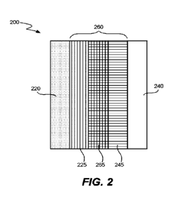
[0023] Figure 2 is a schematic illustration of a membrane electrode assembly
(MEA) for
5 use in a CO. reduction reactor (CRR) according to various embodiments.
[0024] Figure 3 is a schematic illustration of a carbon dioxide (CO2)
electrolyzer
configured to receive water and CO2 (e.g., humidified or dry gaseous CO2) as a
reactant at
a cathode and expel carbon monoxide (CO) as a product.
[0025] Figure 4 illustrates an example construction of a CO, reduction MEA
having a
10 cathode catalyst layer, an anode catalyst layer, and an anion-conducting
polymer electrolyte
membrane (PEM).
[0026] Figure 5 illustrates an example construction of a CO reduction MEA 5
having a
cathode catalyst layer, an anode catalyst layer, and an anion-conducting PEM.
[0027] Figure 6 is a schematic drawing that shows a possible morphology for
two
15 different kinds of catalysts supported on a catalyst support particle.
[0028] Figure 7 shows examples of shapes and sizes of metal catalyst
particles.
[0029] Figure 8 shows an example of a method according to certain embodiments
in
which an ionomer is used as a ligand to direct the synthesis of a nanocrystal
catalyst.
[0030] Figure 9 is a schematic illustration of a bipolar interface of a MEA.
20 [0031] Figures 10A-10D are schematic illustrations of bipolar interfaces
of MEAs that
are configured to resist delamination.
[0032] Figure 11 is a schematic illustration of layers of a MEA, including an
anion-
conducting polymer layer (AEM) and a polymer electrolyte membrane (PEM).
[0033] Figure 12 shows Faraday efficiency for COx electrolyzers having bipolar
MEAs
25 with different thicknesses of AEM.
7
CA 03159447 2022-5-25
WO 2021/108446
PCT/US2020/062080
[0034] Figure 13 shows cell voltages for COx electrolyzers having bipolar MEAs
with
different thicknesses of AEM.
DETAILED DESCRIPTION
INTRODUCTION AND GOALS OF MEA
5 [0035] A membrane electrode assembly (MEA) is described here. It may be
used in a
CO. reduction reactor. CO. may be carbon dioxide (CO2), carbon monoxide (CO),
C032
(carbonate ion), HCO3- (bicarbonate ion), or combinations thereof. The MEA
contains an
anode layer, a cathode layer, electrolyte, and optionally one or more other
layers. The layers
may be solids and/or soft materials . The layers may include polymers such as
ion-
10 conducting polymers.
[0036] When in use, the cathode of an MEA promotes electrochemical reduction
of CO.
by combining three inputs: CO., ions (e.g., protons) that chemically react
with CO., and
electrons. The reduction reaction may produce CO, hydrocarbons, and/or oxygen
and
hydrogen containing organic compounds such as methanol, ethanol, and acetic
acid. When
15 in use, the anode of an MEA promotes an electrochemical oxidation reaction
such as
electrolysis of water to produce elemental oxygen and protons. The cathode and
anode may
each contain catalysts to facilitate their respective reactions.
[0037] The compositions and arrangements of layers in the MEA may promote high
yield
of a CO. reduction products. To this end, the MEA may facilitate any one or
more of the
20 following conditions: (a) minimal parasitic reduction reactions (non-CO.
reduction
reactions) at the cathode; (b) low loss of CO. reactants at anode or elsewhere
in the MEA;
(c) maintain physical integrity of the MEA during the reaction (e.g., prevent
delamination
of the MEA layers);(d) prevent CO. reduction product cross-over; (e) prevent
oxidation
production (e.g., 02) cross-over; (I) maintain a suitable environment at the
cathode/anode
25 for oxidation/reduction as appropriate; (g) provide pathway for desired
ions to travel
between cathode and anode while blocking undesired ions; and (h) minimize
voltage losses.
COx REDUCTION SPECIFIC PROBLEMS
[0038] Polymer-based membrane assemblies such as MEAs have been used in
various
electrolytic systems such as water electrolyzers and in various galvanic
systems such as fuel
8
CA 03159447 2022-5-25
WO 2021/108446
PCT/US2020/062080
cells. However, CO x reduction presents problems not encountered, or
encountered to a
lesser extent, in water electrolyzers and fuel cells.
[0039] For example, for many applications, an MEA for CO x reduction requires
a
lifetime on the order of about 50,000 hours or longer (approximately five
years of
5 continuous operation), which is significantly longer than the expected
lifespan of a fuel cell
for automotive applications; e.g., on the order of 5,000 hours. And for
various applications,
an MEA for CO, reduction employs electrodes having a relatively large
geometric surface
area by comparison to MEAs used for fuel cells in automotive applications. For
example,
MEAs for CO, reduction may employ electrodes having geometric surface areas
(without
10 considering pores and other nonplanar features) of at least about 500
cm2.
[0040] CO, reduction reactions may be implemented in operating environments
that
facilitate mass transport of particular reactant and product species, as well
as to suppress
parasitic reactions. Fuel cell and water electrolyzer MEAs often cannot
produce such
operating environments. For example, such MEAs may promote undesirable
parasitic
15 reactions such as gaseous hydrogen evolution at the cathode and/or
gaseous CO2 production
at the anode.
[0041] In some systems, the rate of a CO, reduction reaction is limited by the
availability
of gaseous CO, reactant at the cathode. By contrast, the rate of water
electrolysis is not
significantly limited by the availability of reactant: liquid water tends to
be easily accessible
20 to the cathode and anode, and electrolyzers can operate close to highest
current density
possible.
MEA CONFIGURATIONS
MEA general arrangement
[0042] In certain embodiments, an MEA has a cathode layer, an anode layer, and
a
25 polymer electrolyte membrane (PEM) between the anode layer and the
cathode layer. The
polymer electrolyte membrane provides ionic communication between the anode
layer and
the cathode layer, while preventing electronic communication, which would
produce a short
circuit. The cathode layer includes a reduction catalyst and a first ion-
conducting polymer.
The cathode layer may also include an ion conductor and/or an electron
conductor. The
30 anode layer includes an oxidation catalyst and a second ion-conducting
polymer. The anode
9
CA 03159447 2022-5-25
WO 2021/108446
PCT/US2020/062080
layer may also include an ion conductor and/or an electron conductor. The PEM
includes a
third ion-conducting polymer.
[0043] In certain embodiments, the MEA has a cathode buffer layer between the
cathode
layer and the polymer electrolyte membrane. The cathode buffer includes a
fourth ion-
5 conducting polymer.
[0044] In certain embodiments, the MEA has an anode buffer layer between the
anode
layer and the polymer electrolyte membrane. The anode buffer includes a fifth
ion-
conducting polymer.
[0045] In connection with certain MEA designs, there are three available
classes of ion-
conducting polymers: anion-conductors, cation-conductors, and mixed cation-and-
anion-
conductors. In certain embodiments, at least two of the first, second, third,
fourth, and fifth
ion-conducting polymers are from different classes of ion-conducting polymers.
[0046] For context, as shown in Figure 1, a membrane electrode assembly (MEA)
100
used for water electrolysis has a cathode 120 and an anode 140 separated by an
ion-
15 conducting polymer layer 160 that provides a path for ions to travel
between the cathode
120 and the anode 140. The cathode 120 and the anode 140 each contain ion-
conducting
polymer and catalyst particles. One or both may also include electronically
conductive
catalyst support. The ion-conducting polymer in the cathode 120, anode 140,
and ion-
conducting polymer layer 160 are either all cation-conductors or all anion-
conductors.
20 [0047] The MEA 100 is not suitable for use in a carbon oxide reduction
reactor (CRR).
When all of the ion-conducting polymers are cation-conductors, the environment
favors H2
generation, an unwanted side reaction, at the cathode layer. The production of
hydrogen
lowers the rate of CO, product production and lowers the overall efficiency of
the process.
[0048] When all of the ion-conducting polymers are anion-conductors, then CO2
reacts
25 with hydroxide anions in the ion-conducting polymer at the cathode to
form bicarbonate
anions. The electric field in the reactor moves the bicarbonate anions from
the cathode side
of the cell to the anode side of the cell. At the anode, bicarbonate anions
can decompose
back into CO2 and hydroxide. This results in the net movement of CO2 from the
cathode to
the anode of the cell, where it does not react and is diluted by the anode
reactants and
30 products. This loss of CO2 to the anode side of the cell reduces the
efficiency of the process.
CA 03159447 2022-5-25
WO 2021/108446
PCT/US2020/062080
Conductivity and selectivity of ion-conducting polymers for MEA layers
[0049] The term "ion-conducting polymer" is used herein to describe a polymer
electrolyte having greater than about 1 mS/cm specific conductivity for anions
and/or
cations. The term "anion-conductor" describes an ion-conducting polymer that
conducts
5 anions primarily (although there will still be some small amount of
cation conduction) and
has a transference number for anions greater than about 0.85 at around 100
micron thickness.
The terms "cation-conductor" and/or "cation-conducting polymer" describe an
ion-
conducting polymer that conducts cations primarily (e.g., there can still be
an incidental
amount of anion conduction) and has a transference number for cations greater
than
10 approximately 0.85 at around 100 micron thickness. For an ion-conducting
polymer that is
described as conducting both anions and cations (a "cation-and-anion-
conductor"), neither
the anions nor the cations has a transference number greater than
approximately 0.85 or less
than approximately 0.15 at around 100 micron thickness. To say a material
conducts ions
(anions and/or cations) is to say that the material is an ion-conducting
material or ionomer.
15 Examples of ion-conducting polymers of each class are provided in the
below Table.
Ion-Conducting Polymers
Class Description
Common Features Examples
A. Anion- Greater than
Positively charged aminated tetrainethyl
conducting approximately 1 mSicrn functional
groups are polyphertylene;
specific conductivity
covalently bound to poly(ethylene-co-
for anions, which have the
polymer tetrafluoroethylene)- based
a transference number , backbone
quaternary ammonium
greater than
polymer; quatemized
approximately 0.85 at
polysul lone
around 100 micron
thickness
11
CA 03159447 2022-5-25
WO 2021/108446
PCT/US2020/062080
B. Conducts
Greater than Salt is soluble in the .. polyethylene oxide;
both anions and approximately 1 triSicrn polymer and
the salt polyethylene glycol;
cations conductivity for ions ions
can move poly(vinylidene fluoride);
(including both cations through the polymer polyurethane
and anions), which have material
a transference number ,
between approximately
0.15 and 0.85 at around
100 micron thickness
C. Cation-
Greater than Negatively charged perfluorosulfonic acid
conducting approximately 1 mS/crn functional
groups are polytetrafluoroethylene
specific conductivity
covalently bound to co-polymer; sulfonated
for cations, which have the polymer
poly(ether ether ketone);
a transference number
backbone
greater than
poly(styrene sulfonic acid-
-comaleic acid)
approximately 0.8 at
around 100 micron
thickness
[0050] Some Class A ion-conducting polymers are known by tradenames such as
2259-
60 (Pall RAI), AHA by Tokuyama Co, fumasep FAA- (fumatech GbbH), Sustanion ,
Morgane ADP by Solvay, or Tosflex SF-17 by Tosoh anion exchange membrane
material.
5
Further class A ion-conducting polymers include
HNN5/HNN8 by lonomr, FumaSep by
Fumatech, TM! by Orion, and PAP-TP by W7energy. Some Class C ion-conducting
polymers are known by tradenames such as various formulations of Nafion
(DuPontTm),
GORE-SELECT (Gore), fumapem(10 (fumatech GmbH), and Aquivion PFSA (Solvay).
Polymeric structures
10
[0051] Examples of polymeric structures that can
include an ionizable moiety or an ionic
moiety and be used as ion-conducting polymers in the MEAs described here are
provided
below. The ion-conducting polymers may be used as appropriate in any of the
MEA layers
that include an ion-conducting polymer. Charge conduction through the material
can be
controlled by the type and amount of charge (e.g., anionic and/or cationic
charge on the
15
polymeric structure) provided by the
ionizable/ionic moieties. In addition, the composition
can include a polymer, a homopolymer, a copolymer, a block copolymer, a
polymeric blend,
other polymer-based forms, or other useful combinations of repeating monomeric
units. As
12
CA 03159447 2022-5-25
WO 2021/108446
PCT/US2020/062080
described below, an ion conducting polymer layer may include one or more of
crosslinks,
linking moieties, and arylene groups according to various embodiments. In some
embodiments, two or more ion conducting polymers (e.g., in two or more ion
conducting
polymer layers of the MEAL) may be crosslinked.
5 [0052] Non-limiting monomeric units can include one or more of the
following:
-EArd- iAr-Lf +Ak+
, or
in which Ar is an optionally
substituted
arylene or aromatic; Ak is an optionally substituted alkylene, haloalkylene,
aliphatic,
heteroalkylene, or heteroaliphatic; and L is a linking moiety (e.g., any
described herein) or
can be -C(R7)(R8)-. Yet other non-limiting monomeric units can include
optionally
substituted arylene, aryleneoxy, alkylene, or combinations thereof, such as
optionally
substituted (ary1)(alkyl)ene (e.g., -Ak-Ar- or -Ak-Ar-Ak- or -Ar-Ak-, in which
Ar is an
optionally substituted arylene and Ak is an optionally substituted alkylene).
One or more
monomeric units can he optionally substituted with one or more ionizable or
ionic moieties
(e.g., as described herein).
15 [0053] One or more monomeric units can be combined to form a polymeric
unit. Non-
limiting polymeric units include any of the following:
-FAr-Lf jAr-Lf fAr-L-j- iAr-LH_Akt -FL-Ar [ Ak+
m
-EAr-L]-1-Ak-H-Ak+ -FL-ArH-Ak-H-Ak-l-
n
m
iAr-L1H-Ak-H-Ak-H-Ar-Lf -EL-Ar-H-Ak-F-FAk¨VE-L-Ar-F
n or
n in
20 which Ar, Ak, L, n, and m can be any described herein. In some
embodiments, each m is
independently 0 or an integer of 1 or more. In other embodiments, Ar can
include two or
more arylene or aromatic groups.
[0054] Other alternative configurations are also encompassed by the
compositions
herein, such as branched configurations, diblock copolymers, triblock
copolymers, random
25 or statistical copolymers, stereoblock copolymers, gradient copolymers,
graft copolymers,
and combinations of any blocks or regions described herein.
[0055] Examples of polymeric structures include those according to any one of
formulas
(I)-(V) and (X)-(XXXIV), or a salt thereof. In some embodiments, the polymeric
structures
13
CA 03159447 2022- 5- 25
WO 2021/108446
PCT/US2020/062080
are copolymers and include a first polymeric structure selected from any one
of formulas
(I)-(V) or a salt thereof; and a second polymeric structure including an
optionally substituted
aromatic, an optionally substituted arylene, a structure selected from any one
of formulas
(I)-(V) and (X)-(XXXIV), or a salt thereof.
5
[0056] In one embodiment, the MW of the ion-
conducting polymer is a weight-average
molecular weight (Mw) of at least 10,000 g/mol; or from about 5,000 to
2,500,000 g/mol.
In another embodiment, the MW is a number average molecular weight (Mn) of at
least
20,000 g/mol; or from about 2,000 to 2,500,000 g/mol.
[0057] In any embodiment herein, each of n, nl, n2, n3, n4, m, ml, m2, or m3
is,
independently, 1 or more, 20 or more, 50 or more, 100 or more; as well as from
1 to
1,000,000, such as from 10 to 1,000,000, from 100 to 1,000,000, from 200 to
1,000,000,
from 500 to 1,000,000, or from 1,000 to 1,000,000.
[0058] Non-limiting polymeric structures can include the following:
R7
R7
R8
n n OP, -
Re - n
R7
R7
1011 ¨
b
b R8
R8
15 n (IV), R9 R14:1
(V), or a salt thereof,
wherein:
each of R7, R8, R9, and RI is, independently, an electron-withdrawing moiety,
H, optionally substituted aliphatic, alkyl, heteroaliphatic, heteroalkylene,
aromatic, aryl, or
arylalkylene, wherein at least one of R7 or R8 can include the electron-
withdrawing moiety
20
or wherein a combination of R7 and R8 or R9 and R1
can be taken together to form an
optionally substituted cyclic group;
Ar comprises or is an optionally substituted aromatic or arylene (e.g., any
described herein);
each of n is, independently, an integer of 1 or more;
25 each of rings a-c can be optionally substituted; and
rings a-c, R7, R8, R9, and RI can optionally comprise an ionizable or ionic
moiety.
14
CA 03159447 2022- 5- 25
WO 2021/108446
PCT/US2020/062080
[0059] Further non-limiting polymeric structures can include one or more of
the
following:
R7 R7
R7
401 _
L8A
Lark
L8A
I
n
X8A x8A1
x8A" X8A
9
9 9 9
R7
R7
R7
14111 _
\ /
L8A L8A
/\ n L13. L13"
i
X8A IF LB" x8A' x8A"
1
x8A x8A" XII31 X13" XII3' X13"
9
9 9
5 or a salt thereof, wherein:
R7 can be any described herein (e.g., for formulas (I)-(V));
n is from 1 or more;
each Ls', LB', and LB- is, independently, a linking moiety; and
each X8A, x8A', VA", XIV, and X13- is, independently, an ionizable or ionic
moiety.
10 Yet other polymeric structures include the following:
01 ¨
0 1
0 } n
N 'cln
N q
. .õ
R9t µR1 00, Rg R10 (XI),
e 4 \
R7 R7
- m
_ go
Ak I F Ak
....".,..-4 d \c/ \ / \ e /
R8 0 n1 n2 n3 R81 ../. n4
b
g * a
N....
(XII),
"--\
(XIII),
CA 03159447 2022- 5- 25
WO 2021/108446
PCT/US2020/062080
N -....., 0 N N -...õ 0
N *
L *
'alb
d,¨ ¨(11a lb d\
N ..--- N N ---
- N
- n (XIV), -
m
(XV),
0
----
b I
ILI & . L2 \d/ L3 0
m (XVI),
_[L1 * L2 \b/ 0 . 0 \ di
m (XVII),
6 Li \b, L2 et, L31_ F 1 Fi li HI 1
ml m2 ms FFHH (XVIII), m (XIX),
F I 1 i II ¨Hi Rqi tL1 Ri
1
F F H
mi mi
mi
R2
L3 f \ R2 1
R2 1
L2 L2 L3 41L2 L3
0 m2
m2
(XX),
(XXI),
(XXII),
Ri
Ri
Ri
Ri
t O-CH2 I Cl-I2 I
CH2 I
f CH2i
Li
i Li I
I 1 i Li I
I m
I m R8
R8 (XXIII),
ans (XXIV), R8 (XXV), m
i Ri
CH2 1
0 I ml
Li
OHL2¨Of L3-0
R1
L2¨He
m2
f Li
[ Lit
I t
(XXVI), R8 (XXVII),
R2 ms (XXVIII),
16
CA 03159447 2022-5-25
WO 2021/108446
PCT/US2020/062080
Rl R2
_______________________ ir1 =N ______ L2
P=N 0 * 1_0_\ L2 *
P
L4 1ml L3 Im2 f_N
R8 R3 (XXIX), 0
(XXX),
0
b L2 SO
0 rn (XXXI),
0
0
NE) 1-0¨ 2 1_3¨N¨ce74
b L
o
0 I" (XXXII),
* 0+
n (XXXIII),
(XXXIV), or a salt thereof, wherein:
5
each of RI, R2, R3, R7, R8, R9, and Rl is,
independently, an electron-withdrawing
moiety. It optionally substituted aliphatic, alkyl, heteroaliphatic,
heteroalkylene, aromatic,
aryl, or arylalkylene, wherein at least one of R7 or R8 can include the
electron-withdrawing
moiety or wherein a combination of R7 and R8 or R9 and RI can be taken
together to form
an optionally substituted cyclic group;
10 each Ak is or comprises an optionally substituted aliphatic,
alkylene, haloalkylene,
heteroaliphatic, or heteroalkylene;
each Ar is or comprises an optionally substituted arylette or aromatic;
each of L, LI, L2, L3, and L4 is, independently, a linking moiety;
each of n, nl, n2, n3, n4, m, ml, m2, and m3 is, independently, an integer of
1 or
15 more;
q is 0, 1, 2, or more;
each of rings a-i can be optionally substituted; and
rings a-i, R7, R8, R9, and RR' can optionally include an ionizable or ionic
moiety.
20
[0060] In particular embodiments (e.g., of formula
(XIV) or (XV)), each of the nitrogen
atoms on rings a and/or b are substituted with optionally substituted
aliphatic, alkyl,
aromatic, aryl, an ionizable moiety, or an ionic moiety. In some embodiments,
one or more
17
CA 03159447 2022-5-25
WO 2021/108446
PCT/US2020/062080
hydrogen or fluorine atoms (e.g., in formula (XIX) or (XX)) can be substituted
to include
an ionizable moiety or an ionic moiety (e.g., any described herein). In other
embodiments,
the oxygen atoms present in the polymeric structure (e.g., in formula XXVIII)
can be
associated with an alkali dopant (e.g., IC).
5 [0061]
In particular examples, Ar, one or more of rings a-
i (e.g., rings a, b, f, g, It, or 1),
L, Li, L2, L3, L4, Ak, R7, R8, R9, and/or Ri can be optionally substituted
with one or more
ionizable or ionic moieties and/or one or more electron-withdrawing groups.
Yet other non-
limiting substituents for Ar, rings (e.g., rings a-i), L, Ak, R7, Rs, R9, and
RI include one or
more described herein, such as cyano, hydroxy, nitro, and halo, as well as
optionally
10 substituted aliphatic, alkyl, alkoxy, alkoxyalkyl, amino, aminoalkyl,
aryl, arylalkylene,
aryloyl, aryloxy, arylalkoxy, hydroxyalkyl, and haloalkyl.
[0062] In some embodiments, each of RI, R2, and R3 is, independently, II,
optionally
substituted aromatic, aryl, aryloxy, or arylalkylene. In other embodiments
(e.g., of formulas
(I)-(V) or (XII)), R7 includes the electron-withdrawing moiety. In yet other
embodiments,
15 Rs, R9, and/or RI includes an ionizable or ionic moiety.
[0063] In one instance, a polymeric subunit can lack ionic moieties.
Alternatively, the
polymeric subunit can include an ionic moiety on the Ar group, the L group,
both the Ar
and L groups, or be integrated as part of the L group. Non-limiting examples
of ionizable
and ionic moieties include cationic, anionic, and multi-ionic group, as
described herein.
20 [0064] In any embodiment herein, the electron-withdrawing moiety can
include or be an
optionally substituted haloalkyl, eyano (CN), phosphate (e.g., -
0(P=0)(ORPI)(ORP2) or -0-
[P(=0)(ORPI)-01p3-RP2), sulfate (e.g., -0-8(=0)2(0R5I)), sulfonic acid (-
S03H), sulfonyl
(e.g.,
-S02-CF3), difluomboranyl (-BF2), borono (B(OH)2), thiocyanato (-SCN), or
piperidinium.
25 Yet other non-limiting phosphate groups can include derivatives of
phosphoric acid, such
as orthophosphoric acid, pyrophosphoric acid, tripolyphosphoric acid,
tetrapolyphosphoric
acid, trimetaphosphoric acid, and/or phosphoric anhydride, or combinations
thereof.
[0065] Yet other polymeric units can include poly(benzimidazole) (PHI),
polyphenylene
(PP), polyimide (PI), poly(ethyleneimine) (PEI), sulfonated polyimide (SPI),
polysulfone
30 (PSF), sulfonated polysulfone (SPSF), poly(ether ether ketone) (PEEK),
PEEK with cardo
groups (PEEK-WC), polyethersulfone (PES), sulfonated polyethersulfone (SPES),
18
CA 03159447 2022-5-25
WO 2021/108446
PCI1LTS2020/062080
sulfonated poly(ether ether ketone) (SPEEK), SPEEK with cardo groups (SPEEK-
WC),
poly(p-phenylene oxide) (PPO), sulfonated polyphenylene oxide (SPPO), ethylene
tetrafluoroethylene (ETFE), polytetrafluoroethylene (PTFE),
poly(epichlorohydrin)
(PECH), poly(styrene) (PS), sulfonated poly(styrene) (SPS), hydrogenated
poly(butadiene-
5 styrene) (HPBS), styrene divinyl benzene copolymer (SDVB), styrene-
ethylene-butylene-
styrene (SEBS), sulfonated bisphenol-A-polysulfone (SPSU), poly(4-phenoxy
benzoy1-1,4-
phenylene) (PPBP), sulfonated poly(4-phenoxy benzoy1-1,4-phenylene) (SPPBP),
poly(vinyl alcohol) (PVA), poly(phosphazene), poly(aryloxyphosphazene),
polyetherimide,
as well as combinations thereof.
Crosslinking
[0066] In some embodiments, crosslinking is present within an ion conducting
polymer
layer and/or between ion conducting polymer layers. Crosslinking within a
material can be
promoted by use of crosslinking reagents. For instance, the composition can
include
polymeric units, and a crosslinking reagent can be used to provide
crosslinking between
15 polymeric units. For instance, if the polymeric units (P1 and P2)
include a leaving group,
then a diamine crosslinking reagent (e.g., H2N-Ak-NH2) can be used to react
with the
polymeric units by displacing the leaving group and forming an amino-
containing
crosslinker within the composition (e.g., thereby forming P1-NH-Ak-NH-P2).
Crosslinkers
can be introduced by fanning a polymer composition and then exposing the
composition to
20 a crosslinking reagent to form crosslinker.
[0067] Depending on the functional group present in the material, the
crosslinking
reagent can include a nucleophilic group (e.g., an amine or a hydroxyl) or an
electrophilic
group (e.g., a carbonyl). Thus, non-limiting crosslinking reagents can include
amine-
containing reagents, hydroxyl-containing reagents, carboxylic acid-containing
reagents,
25 acyl halide-containing reagents, or others. Further crosslinking
reagents can include:
Ak-EX Ark -EL-X
L3 or L3 or
L3, in which Ak is an optionally substituted aliphatic
or alkylene; Ar is an optionally substituted aromatic or arylene; L is a
linking moiety (e.g.,
any herein, such as a covalent bond, optionally substituted alkylene,
aliphatic, etc.); L3 is
an integer that is 2 or more (e.g., 2, 3, 4, 5, 6, or more); and X is halo,
hydroxyl, optionally
30 substituted amino (e.g., NRE\IIRN2, in which each of le1 and RI42 is,
independently, H or
optionally substituted alkyl), hydroxyl, carboxyl, acyl halide (e.g., -C(0)-R,
in which R is
19
CA 03159447 2022-5-25
WO 2021/108446
PCT/US2020/062080
halo), carboxyaldehyde (e.g., -C(0)H), or optionally substituted alkyl. Non-
limiting
crosslinking reagents can include terephthalaldehyde, glutaraldettyde, ortho-
xylene, para-
xylene, meta-xylene, or a multivalent amine, such as diantine, triamine,
tetraamine,
pentaamine, etc., including 1,6-diaminohexane (hexanediamine), 1,4-
diaminobutane, 1,8-
diaminooctane, propane- 1,2,3-triamine, [1,1':3',1"-terpheny1]-4,41',5'-
triantine, and others.
[0068] After reacting the crosslinking reagent, the composition can include
one or more
crosslirtkers within the composition. If the crosslinking reagent is bivalent,
then a
crosslirtker can be present between two of any combination of polymeric
structures,
polymeric units, and ionizable/ionic moieties (e.g., between two polymeric
units, between
two ionizable/ionic moieties, etc.). If the crosslinking reagent is trivalent
or of higher it
valency, then the crosslinker can be present between any n number of polymeric
units,
linking moieties, ionizable moieties, and/or ionic moieties. Non-limiting
crosslirtkers
present in the composition include those formed after reacting a crosslinking
reagent. Thus,
examples of crosslinkers can include:
Ak-[-X'
L3 or I-3 or
L3, in which Ak is an optionally substituted aliphatic
or an optionally substituted alkylene, Ar is an optionally substituted
aromatic or an
optionally substituted arylene, L is a linking moiety (e.g., any herein, such
as a covalent
bond, optionally substituted alkylene, optionally substituted aliphatic,
etc.), L3 is an integer
that is 2 or more (e.g., 2, 3, 4, 5, 6, or more), and X' is a reacted form of
X. In some
embodiments, X' is absent, -0-,
-C(0)-, or -Ak-, in which RN1 is H or optionally substituted alkyl, and Ak is
optionally substituted alkylene, optionally substituted heteroalkylene,
optionally substituted
aliphatic, or optionally substituted heteroaliphatic.
Ionizable and ionic moieties
[0069] The polymers described herein include one or more ionizable or ionic
moieties.
Such moieties can include an anionic or cationic charge, such as in an ionic
moiety.
Alternatively, an ionizable moiety includes a functional group that can be
readily convened
into an ionic moiety, such as an ionizable moiety of a carboxy group (-CO2H)
that can be
readily deprotonated to form a carboxylate anion (-0O21. As used herein, the
terms
"ionizable" and "ionic" are used interchangeably.
CA 03159447 2022- 5- 25
WO 2021/108446
PCT/US2020/062080
[0070] Moieties can be characterized as an acidic moiety (e.g., a moiety can
be
deprotonated or can carry a negative charge) or a basic moiety (e.g., a moiety
that can be
protonated or carry a positive charge). In particular embodiments, the moiety
can be a multi-
ionic moiety, which can include a plurality of acidic moieties, a plurality of
basic moieties,
5
or a combination thereof (e.g., such as in a
zwitterionic moiety). Further moieties can
include a zwitterionic moiety, such as those including an anionic moiety
(e.g., hydroxyl or
a deprotonated hydroxyl) and a cationic moiety (e.g., ammonium).
[0071] The ionic moieties herein can be connected to the parent structure by
way of one
or more linking moieties. Furthermore, a single ionic moiety can be extended
from a single
10
linking moiety, or a plurality of ionic moieties
can have one or more linking moieties
therebetween. For instance, the ionic moiety can have any of the following
structures: -L"-
or
-LA-(LAIXA)L2 or -LA-(XA-LAIXA')L2 or -LA-XA-LAIXAP-LA"-XA", in which each LA,
LA',
and LA" is a linking moiety (e.g., any described herein); each XA, XA', and
XA" includes,
15
independently, an acidic moiety, a basic moiety, a
multi-ionic moiety, a cationic moiety, or
an anionic moiety; and L2 is an integer of 1, 2, 3, or more (e.g., from 1 to
20). Non-limiting
LA and LA1' can be -(CH2)p-, -0(CH2)Li-, -(CF2)11-, -0(CF2)L1-, or -S(CF2)Li-,
in which Li
is an integer from 1 to 3; and XA is any ionizable or ionic moiety described
herein.
[0072] Non-limiting ionizable or ionic moieties include carboxy (-CO2H),
carboxylate
20
anion (-0O2-), guanidinium cation, sulfo (-
502011), sulfonate anion (-5020), sulfonium
cation, sulfate, sulfate anion, phosphono (e.g., -P(=0)(OH)2), phosphonate
anion,
phosphate, phosphate anion, phosphonium cation, phosphazenium cation, amino
(e.g., -NRN IRN2), ammonium cation (e.g., aliphatic or aromatic ammonium),
heterocyclic
cation (e.g., including piperidinium, pyrrolidinium, pyridinium, pyrazolium,
imidazolium,
25 quinolinium, isoquinolinium, acridinium, quinolinium, isoquinolinium,
acridinium,
pyridazinium, pyrimidinium, pyrazinium, phenazinium, 1,4-
diazabicyclo[2.2.21octarie
(DABCO) cation, 4-methy1-1,4-diazoniabicyclo[2.2.2]octan-1-y1 (MAABCO)
cation), and
1-benzy1-1,4-diazoniabicyclo[2.2.21 octane (BABCO) cation), or a salt form
thereof. Such
moieties can be associated with one or more counterions. For instance, a
cationic moiety
30 can be associated with one or more anionic counterions, and an anionic
moiety can be
associated with one or more cationic counterions.
21
CA 03159447 2022-5-25
WO 2021/108446
PCT/US2020/062080
Arylene Groups
[0073]
Particular moieties herein (e.g.,
polymeric units, linking moieties, and others) can
include an optionally substituted arylene. Such arylene groups include any
multivalent (e.g.,
bivalent, trivalent, tetravalent, etc.) groups having one or more aromatic
groups, which can
include heteroaromatic groups. Non-limiting aromatic groups (e.g., for Ar) can
include any
of the following:
140
6 \õ \d,
\d, d/
b
_
\d/ \e/
d
=
I
g\
RI R" c7
=, in
which each of rings a-i can be optionally substituted (e.g., with any optional
substituents
described herein for alkyl or aryl; or with any ionic moiety described
herein); L' is a linking
moiety (e.g., any described herein); and each of R' and R" is, independently,
H, optionally
substituted alkyl, optionally substituted aryl, or an ionic moiety, as
described herein. Non-
limiting substituents for rings a-i include one or more described herein for
aryl, such as
alkyl, alkoxy, alkoxyalkyl, amino, aminoalkyl, aryl, arylalkylene, aryloyl,
aryloxy,
arylalkoxy, cyano, hydroxy, hydroxyalkyl, nitro, halo, and haloalkyl.
In some
embodiments, L' is a covalent bond, -0-, -NR-, -C(0)-, optionally substituted
alkylene,
heteroalkylene, or arylene.
[0074]
Yet other non-limiting arylene
can include phenylene (e.g., 1,4-phenylene, 1,3-
phenylene, etc.), biphenylene (e.g., 4,4'-biphenylene, 3,3'-biphenylene, 3,4'-
biphenylene,
eta), terphenylene (e.g., 4,4'-terphenylene), diphenyl ether, anthracene
(e.g., 9,10-
anthracene), naphthalene (e.g., 1,5-naphthalene, 1,4-naphthalene, 24-
naphthalene, 2,7-
naphthalene, etc.), tetrafluorophenylene (e.g., 1,4-tetrafluorophenylene, 1,3-
tetrafluorophenylene), and the like.
[0075] Non-limiting examples of linking moieties for arylene include any
herein. In
some embodiments, L' is substituted one or more ionizable or ionic moieties
described
herein. In particular embodiments, L' is optionally substituted alkylene. Non-
limiting
22
CA 03159447 2022-5-25
WO 2021/108446
PCT/US2020/062080
substitutions for L' can include -L'-X", in which LA is a linking moiety
(e.g., any described
herein, such as, -Ak-, -0-Ak-, -Ak-O-, -Ar-, -0-Ar-, or -Ar-O-, in which Ak is
optionally
substituted alkylene and Ar is optionally substituted arylene), and XA is an
acidic moiety, a
basic moiety, or a multi-ionic moiety.
5 Linking moieties
[0076] Particular chemical functionalities herein can include a linking
moiety, either
between the parent structure and another moiety (e.g., an ionic moiety) or
between two (or
more) other moieties. Linking moieties (e.g., L, LI, L2, L3, L4, LA, LA', LA",
LB', La", LsA,
and others) can be any useful multivalent group, such as multivalent forms of
optionally
10 substituted aliphatic, heteroaliphatic, aromatic, or heteroaromatic.
[0077] In any embodiment herein, the linking moiety (e.g., L, LI, L2, L3, or
L4) includes
a covalent bond, spirocyclic bond, -0-, -NRNI-, -C(0)-, -C(0)0-, -0C(0)-, -SO2-
,
optionally substituted aliphatic, alkylene (e.g., -CH2-, -C(CH3)2-, or -CR2-,
in which R is H,
alkyl, or haloalkyl), alkyleneoxy, haloalkylene (e.g., -CF2- or -C(CF3)2-),
hydroxyalkylene,
15 heteroaliphatic, heteroalkylene, aromatic, arylene, aryleneoxy,
heterocycle,
heterocyclyldiyl,
-(0-Ak)Li-S02-NRN I -Ak-, -Ak-,
-(Ak-O)Li-,
-C(0)0-Ak-, -Ar-, or -Ar-O-, as well as combinations thereof. In particular
embodiments,
Ak is optionally substituted aliphatic, alkylene, or haloalkylene; RN' is H,
optionally
20 substituted alkyl, or aryl; Ar is an optionally substituted aromatic or
arylene; and Li is an
integer from 1 to 3.
[0078]
In other embodiments, L is an
optionally substituted CI-6 aliphatic, C1_6 alkylene,
or Ci-6 heteroalkylene. The use of short linkers could provide more extensive
polymeric
networks, as shorter linkers could minimize self-cyclization reactions.
25 [0079] In some embodiments, the linking moiety is -(CH2)m-, -0(CH2)1A-, -
(CF2)Lt-,
-0(CF2)n-, or -S(CF2)n- in which L1 is an integer from 1 to 3. In other
embodiments, the
linking moiety is -Ak-O-Ar-Ak-O-Ak- or -Ak-O-Ar-, in which Ak is optionally
substituted
alkylene or haloalkylene, and Ar is an optionally substituted arylene. Non-
limiting
substituted for Ar includes -S02-Ph, in which Ph can be unsubstituted or
substituted with
30 one or more halo.
23
CA 03159447 2022- 5- 25
WO 2021/108446
PCT/US2020/062080
[0080] The polymers described above in the with reference to the Table and
formulas
(I)-(V) and (X)-(XXXIV), including homopolymers and copolymers thereof and
which may
be optionally crosslinIced and may include any of the linking moieties,
arylene groups, and
ionic moieties as described above may be used as appropriate in one or more
layers of the
5 MEA including a cathode catalyst layer, an anode catalyst layer, a
polymer electrolyte
membrane (PEM) layer, a cathode buffer layer, and/or an anode buffer layer.
BIPOLAR MEA FOR COx REDUCTION
[0081] In certain embodiments, the MEA includes a bipolar interface with an
anion-
conducting polymer on the cathode side of the MEA and an interfacing cation-
conducting
10 polymer on the anode side of the MEA. In some implementations, the
cathode contains a
first catalyst and an anion-conducting polymer. In certain embodiments, the
anode contains
a second catalyst and a cation-conducting polymer. In some implementations, a
cathode
buffer layer, located between the cathode and PEM, contains an anion-
conducting polymer.
In some embodiments, an anode buffer layer, located between the anode and PEM,
contains
15 a cation-conducting polymer.
[0082] During operation, an MEA with a bipolar interface moves ions through a
polymer-electrolyte, moves electrons through metal and/or carbon in the
cathode and anode
layers, and moves liquids and gas through pores in the layers.
[0083] In embodiments employing an anion-conducting polymer in the cathode
and/or
20 in a cathode buffer layer, the MEA can decrease or block unwanted
reactions that produce
undesired products and decrease the overall efficiency of the cell. In
embodiments
employing a cation-conducting polymer in the anode and/or in an anode buffer
layer can
decrease or block unwanted reactions that reduce desired product production
and reduce the
overall efficiency of the cell.
25 [0084] For example, at levels of electrical potential used for cathodic
reduction of CO2,
hydrogen ions may be reduced to hydrogen gas. This is a parasitic reaction;
current that
could be used to reduce CO2 is used instead to reduce hydrogen ions. Hydrogen
ions may
be produced by various oxidation reactions performed at the anode in a CO2
reduction
reactor and may move across the MEA and reach the cathode where they can be
reduced to
30 produce hydrogen gas. The extent to which this parasitic reaction can
proceed is a function
24
CA 03159447 2022-5-25
WO 2021/108446
PCT/US2020/062080
of the concentration of hydrogen ions present at the cathode. Therefore, an
MEA may
employ an anion-conducting material in the cathode layer and/or in a cathode
buffer layer.
The anion-conducting material at least partially blocks hydrogen ions from
reaching
catalytic sites on the cathode. As a result, parasitic production of hydrogen
gas generation
5 is decreased and the rate of CO or other product production and the
overall efficiency of the
process are increased.
[0085] Another process that may be avoided is transport of carbonate or
bicarbonate ions
to the anode, effectively removing CO2 from the cathode. Aqueous carbonate or
bicarbonate
ions may be produced from CO2 at the cathode. if such ions reach the anode,
they may
10 decompose and release gaseous CO2. The result is net movement of CO2
from the cathode
to the anode, where it does not get reduced and is lost with oxidation
products. To prevent
the carbonate and bicarbonate ion produced at the cathode from reaching the
anode, the
polymer-electrolyte membrane and/or a anode buffer layer may include a cation-
conducting
polymer, which at least partially blocks the transport of negative ions such
as bicarbonate
15 or carbonate ions to the anode.
[0086] Thus, in some designs, a bipolar membrane structure raises the pH at
the cathode
to facilitate CO2 reduction while a cation-conducting polymer such as a proton-
exchange
layer prevents the passage of significant amounts of CO2, negative ions (e.g.
bicarbonate,
carbonate), hydrogen, and CO2 reduction products (e.g., CO, methane, ethylene,
alcohols)
20 to the anode side of the cell.
[0087] An example MEA 200 for use in COõ reduction is shown in Figure 2. The
MEA
200 has a cathode layer 220 and an anode layer 240 separated by an ion-
conducting polymer
layer 260 that provides a path for ions to travel between the cathode layer
220 and the anode
layer 240. In certain embodiments, the cathode layer 220 includes an anion-
conducting
25 polymer and/or the anode layer 240 includes a cation-conducting polymer. In
certain
embodiments, the cathode layer and/or the anode layer of the MEA are porous.
The pores
may facilitate gas and/or fluid transport and may increase the amount of
catalyst surface
area that is available for reaction.
[0088] The ion-conducting layer 260 may include two or three sublayers: a
polymer
30 electrolyte membrane (PEM) 265, an optional cathode buffer layer 225,
and/or an optional
anode buffer layer 245. One or more layers in the ion-conducting layer may be
porous. In
CA 03159447 2022-5-25
WO 2021/108446
PCT/US2020/062080
certain embodiments, at least one layer is nonporous so that reactants and
products of the
cathode cannot pass via gas and/or liquid transport to the anode and vice
versa. In certain
embodiments, the PEM layer 265 is nonporous. Example characteristics of anode
buffer
layers and cathode buffer layers are provided elsewhere herein.
5 [0089] Figure 3 shows CO2 electrolyzer 303 configured to receive water
and CO2 (e.g.,
humidified or dry gaseous CO2) as a reactant at a cathode 305 and expel CO as
a product.
Electrolyzer 303 is also configured to receive water as a reactant at an anode
307 and expel
gaseous oxygen. Electrolyzer 303 includes bipolar layers having an anion-
conducting
polymer 309 adjacent to cathode 305 and a cation-conducting polymer 311
(illustrated as a
10 proton-exchange membrane) adjacent to anode 307.
[0090]
As illustrated in the
magnification inset of a bipolar interface 313 in electrolyzer
303, the cathode 305 includes an anion exchange polymer (which in this example
is the
same anion-conducting polymer 309 that is in the bipolar layers)
electronically conducting
carbon support particles 317, and metal nanoparticles 319 supported on the
support particles.
15 CO2 and water are transported via pores such as pore 321 and reach metal
nanoparticles 319
where they react, in this case with hydroxide ions, to produce bicarbonate
ions and reduction
reaction products (not shown). CO2 may also reach metal nanoparticles 319 by
transport
within anion exchange polymer 315.
[0091] Hydrogen ions are transported from anode 307, and through the cation-
20 conducting polymer 311, until they reach bipolar interface 313, where
they are hindered
from further transport toward the cathode by anion exchange polymer 309. At
interface
313, the hydrogen ions may react with bicarbonate or carbonate ions to produce
carbonic
acid (H2CO3), which may decompose to produce CO2 and water. As explained
herein, the
resulting CO2 may be provided in gas phase and should be provided with a route
in the MEA
25 back to the cathode 305 where it can be reduced. The cation-conducting
polymer 311
hinders transport of anions such as bicarbonate ions to the anode where they
could react
with protons and release CO2, which would be unavailable to participate in a
reduction
reaction at the cathode.
[0092] As illustrated, a cathode buffer layer having an anion-conducting
polymer may
30 work in concert with the cathode and its anion-conductive polymer to
block transport of
protons to the cathode. While MEAs employing ion conducting polymers of
appropriate
26
CA 03159447 2022-5-25
WO 2021/108446
PCT/US2020/062080
conductivity types in the cathode, the anode, cathode buffer layer, and if
present, an anode
buffer layer may hinder transport of cations to the cathode and anions to the
anode, cations
and anions may still come in contact in the MEA's interior regions, such as in
the membrane
layer.
[0093] As illustrated in Figure 3, bicarbonate and/or carbonate ions combine
with
hydrogen ions between the cathode layer and the anode layer to form carbonic
acid, which
may decompose to form gaseous CO2. It has been observed that MEAs sometime
delaminate, possibly due to this production of gaseous CO2, which does not
have an easy
egress path.
[0094] The delamination problem can be addressed by employing a cathode buffer
layer
having pores. One possible explanation of its effectiveness is that the pores
create paths for
the gaseous carbon dioxide to escape back to the cathode where it can be
reduced. In some
embodiments, the cathode buffer layer is porous but at least one layer between
the cathode
layer and the anode layer is nonporous. This can prevent the passage of gases
and/or bulk
liquid between the cathode and anode layers while still preventing
delamination. For
example, the nonporous layer can prevent the direct passage of water from the
anode to the
cathode. The porosity of various layers in an MEA is described further at
other locations
herein.
Examples of Bipolar MEAs
[0095] As an example, an MEA includes a cathode layer including a 'eduction
catalyst
and a first anion-conducting polymer (e.g., Sustainion, FumaSep FAA-3,
Tokuyama anion
exchange polymer), an anode layer including an oxidation catalyst and a first
cation-
conducting polymer (e.g., PFSA polymer), a membrane layer including a second
cation-
conducting polymer and arranged between the cathode layer and the anode layer
to
conductively connect the cathode layer and the anode layer, and a cathode
buffer layer
including a second anion-conducting polymer (e.g., Sustainion, FumaSep FAA-3,
Tokuyama anion exchange polymer) and arranged between the cathode layer and
the
membrane layer to conductively connect the cathode layer and the membrane
layer. In this
example, the cathode buffer layer can have a porosity between about 1 and 90
percent by
volume, but can additionally or alternatively have any suitable porosity
(including, e.g., no
porosity). In other examples the cathode buffer layer can have any suitable
porosity (e.g.,
between 0.01-95%, 0.1-95%, 0.01-75%, 1-95%, 1-90%, etc.).
27
CA 03159447 2022-5-25
WO 2021/108446
PCT/US2020/062080
[0096] Too much porosity can lower the ionic conductivity of the buffer layer.
In some
embodiments, the porosity is 20% or below, and in particular embodiments,
between 0.1-
20%, 1-10%, or 5-10%. Porosity in these ranges can be sufficient to allow
movement of
water and/or CO2 without losing ionic conductivity. Porosity may be measured
as described
5 further below.
[0097] In a related example, the membrane electrode assembly can include an
anode
buffer layer that includes a third cation-conducting polymer, and is arranged
between the
membrane layer and the anode layer to conductively connect the membrane layer
and the
anode layer. The anode buffer layer preferably has a porosity between about 1
and 90
percent by volume, but can additionally or alternatively have any suitable
porosity
(including, e.g., no porosity). However, in other arrangements and examples,
the anode
buffer layer can have any suitable porosity (e.g., between 0.01-95%, 0.1-95%,
0.01-75%, 1-
95%, 1-90%). As with the cathode buffer layer, in some embodiments, the
porosity is 20%
or below, e.g. 0.1-20%, 1-10%, or 5-10%
15 [0098] In an example, an anode buffer layer may be used in a MEA having
a cathode
catalyst layer with anion exchange polymer, a cathode buffer layer with anion-
exchange
polymer, a membrane with cation-exchange polymer, and an anode buffer layer
with anion-
exchange polymer. In such a structure, the anode buffer layer may be porous to
facilitate
water transport to the membrane / anode buffer layer interface. Water will be
split at this
20 interface to make protons that travel through the membrane and hydroxide
that travels to the
anode catalyst layer. One advantage of this structure is the potential use of
low-cost water
oxidation catalysts (e.g., NiFe0x) that are only stable in basic conditions.
[0099] In another specific example, the membrane electrode assembly includes a
cathode
layer including a reduction catalyst and a first anion-conducting polymer
(e.g., Sustainion,
25 FumaSep FAA-3, Tokuyama anion exchange polymer), an anode layer including
an
oxidation catalyst and a first cation-conducting polymer, a membrane layer
including a
second anion-conducting polymer (e.g., Sustainion, FumaSep FAA-3, Tokuyama
anion
exchange polymer) and arranged between the cathode layer and the anode layer
to
conductively connect the cathode layer and the anode layer, and an anode
buffer layer
30 including a second cation-conducting polymer and arranged between the
anode layer and
the membrane layer to conductively connect the anode layer and the membrane
layer.
28
CA 03159447 2022-5-25
WO 2021/108446
PCT/US2020/062080
[0100] An MEA containing an anion-exchange polymer membrane and an anode
buffer
layer containing cation-exchange polymer may be used for CO reduction. In this
case, water
would form at the membrane / anode buffer layer interface. Pores in the anode
buffer layer
could facilitate water removal. One advantage of this structure would be the
use of an acid
5 stable (e.g., Ir0,0 water oxidation catalyst.
[0101] In a related example, the membrane electrode assembly can include a
cathode
buffer layer that includes a third anion-conducting polymer and is arranged
between the
cathode layer and the membrane layer to conductively connect the cathode layer
and the
membrane layer. The third anion-conducting polymer can be the same or
different from the
10 first and/or second anion-conducting polymer. The cathode buffer layer
preferably has a
porosity between about 1 and 90 percent by volume but can additionally or
alternatively
have any suitable porosity (including, e.g., no porosity). However, in other
arrangements
and examples, the cathode buffer layer can have any suitable porosity (e.g.,
between 0.01-
95%, 0.1-95%, 0.01-75%, 1-95%, 1-90%). In some embodiments, the porosity is
20% or
15 below, and in particular embodiments, between 0.1-20%, 1-10%, or 5-10%.
[0102] In an example, a cathode catalyst layer composed of Au nanoparticles
4nin in
diameter supported on Vulcan XC72R carbon and mixed with TM1 (mTPN-1) anion
exchange polymer electrolyte (from Orion). Layer is -15um thick,
Au/(Au+C)=20wt%,
TM1 to catalyst mass ratio of 0.32, mass loading of 1.4-1.6 mg/cm2 (total
Au+C), estimated
20 porosity of 0.56. Anion-exchange polymer layer composed of TM1 and PTFE
particles.
FIFE is approximately 200nm in diameter. TM1 molecular weight is 30k-45k.
Thickness
of the layer is -15um. PTFE may introduce porosity of about 8%. Proton-
exchange
membrane layer composed of perfluorosulfonic acid polymer (e.g., Nafion 117).
Thickness
is approximately 183um. Membrane forms a continuous layer that prevents
significant
25 movement of gas (CO2. CO, H2) through the layer. Anode catalyst layer
composed of Jr or
IrOx nanoparticles (100-200 nm aggregates) that is 10 um thick
ANION EXCHANGE MEMBRANE-ONLY MEA FOR COx REDUCTION
[0103] In some embodiments, an MEA does not contain a cation-conducting
polymer
layer. In such embodiments, the electrolyte is not a cation-conducting polymer
and the
30 anode, if it includes an ion-conducting polymer, does not contain a cation-
conducting
polymer. Examples are provided herein.
29
CA 03159447 2022-5-25
WO 2021/108446
PCT/US2020/062080
[0104] An anion-exchange membrane (AEM)-only (AEM-only) MEA allows
conduction of anions across the MEA. In embodiments in which none of the MEA
layers
has significant conductivity for cations, hydrogen ions have limited mobility
in the MEA.
In some implementations, an AEM-only membrane provides a high pH environment
(e.g.,
at least about pH 7) and may facilitate CO2 and/or CO reduction by suppressing
the
hydrogen evolution parasitic reaction at the cathode. As with other MEA
designs, the AEM-
only MEA allows ions, notably anions such as hydroxide ions, to move through
polymer-
electrolyte. The pH may be lower in some embodiments; a pH of 4 or greater may
be high
enough to suppress hydrogen evolution. The AEM-only MEA also permits electrons
to
move to and through metal and carbon in catalyst layers. In embodiments,
having pores in
the anode layer and/or the cathode layer, the AEM-only MEA permits liquids and
gas to
move through pores.
[0105] In certain embodiments, the AEM-only MEA comprises an anion-exchange
polymer electrolyte membrane with an electrocatalyst layer on either side: a
cathode and an
anode. In some embodiments, one or both electrocatalyst layers also contain
anion-exchange
polymer-electrolyte.
[0106] In certain embodiments, an AEM-only MEA is formed by depositing cathode
and
anode electrocatalyst layers onto porous conductive supports such as gas
diffusion layers to
form gas diffusion electrodes (GDEs) and sandwiching an anion-exchange
membrane
between the gas diffusion electrodes.
[0107] In certain embodiments, an AEM-only MEA is used for CO2 reduction. The
use
of an anion-exchange polymer electrolyte avoids low pH environment that
disfavors CO2
reduction. Further, water is transported away from the cathode catalyst layer
when an AEM
is used, thereby preventing water build up (flooding) which can block reactant
gas transport
in the cathode of the cell.
[0108] Water transport in the MEA occurs through a variety of mechanisms,
including
diffusion and electro-osmotic drag. In some embodiments, at current densities
of the CO2
electrolyzers described herein, electro-osmotic drag is the dominant
mechanism. Water is
dragged along with ions as they move through the polymer electrolyte. For a
cation-
exchange membrane such as Nation membrane, the amount of water transport is
well
characterized and understood to rely on the pre-treatment/hydration of the
membrane.
CA 03159447 2022-5-25
WO 2021/108446
PCT/US2020/062080
Protons move from positive to negative potential (anode to cathode) with. each
carrying 2-
4 water molecules with it, depending on pretreatment. In anion-exchange
polymers, the
same type of effect occurs. Hydroxide, bicarbonate, or carbonate ions moving
through the
polymer electrolyte will 'drag' water molecules with them. hi the anion-
exchange MEAs,
5
the ions travel from negative to positive voltage,
so from cathode to anode, and they carry
water molecules with them, moving water from the cathode to the anode in the
process.
[0109] In certain embodiments, an AEM-only MEA is employed in CO reduction
reactions. Unlike the CO2 reduction reaction, CO reduction does not produce
carbonate or
bicarbonate anions that could transport to the anode and release valuable
reactant.
10
[0110] Figure 4 illustrates an example
construction of a CO), reduction MEA 401 having
a cathode catalyst layer 403, an anode catalyst layer 405, and an anion-
conducting PEM
407. In certain embodiments, cathode catalyst layer 403 includes metal
catalyst particles
(e.g., nanoparticles) that are unsupported or supported on a conductive
substrate such as
carbon particles. In some implementations, cathode catalyst layer 403
additionally includes
15
an anion-conducting polymer. The metal catalyst
particles may catalyze COõ reduction,
particularly at pH greater than a threshold pH, which may be pH 4-7, for
example,
depending on the catalyst. In certain embodiments, anode catalyst layer 405
includes metal
oxide catalyst particles (e.g., nanoparticles) that are unsupported or
supported on a
conductive substrate such as carbon particles. In some implementations, anode
catalyst
20
layer 403 additionally includes an anion-
conducting polymer. Examples of metal oxide
catalyst particles for anode catalyst layer 405 include iridium oxide, nickel
oxide, nickel
iron oxide, iridium ruthenium oxide, platinum oxide, and the like. Anion-
conducting PEM
407 may comprise any of various anion-conducting polymers such as, for
example,
HNN5/HNN8 by Ionomr, PumaSep by Fumate-ch, TM! by Orion, PAP-TP by W7energy,
25
Sustainion by Dioxide Materials, and the like.
These and other anion-conducting polymer
that have an ion exchange capacity (1EC) ranging from 1.1 to 2.6 nunolig,
working pH
ranges from 0-14, bearable solubility in some organic solvents, reasonable
thermal stability
and mechanical stability, good ionic conductivity/ASR and acceptable water
uptake/swelling ratio may be used. The polymers may be chemically exchanged to
certain
30
anions instead of halogen anions prior to use. In
some embodiments, the anion-conducting
polymer may have an LEC of 1 to 3.5 mmolig.
31
CA 03159447 2022-5-25
WO 2021/108446
PCT/US2020/062080
[0111] As illustrated in Figure 4, CO x such as CO2 gas may be provided to
cathode
catalyst layer 403. In certain embodiments, the CO2 may be provided via a gas
diffusion
electrode. At the cathode catalyst layer 403, the CO2 reacts to produce
reduction product
indicated generically as Cx0yHz. Anions produced at the cathode catalyst layer
403 may
5
include hydroxide, carbonate, and/or bicarbonate.
These may diffuse, migrate, or otherwise
move to the anode catalyst layer 405. At the anode catalyst layer 405, an
oxidation reaction
may occur such as oxidation of water to produce diatomic oxygen and hydrogen
ions. In
some applications, the hydrogen ions may react with hydroxide, carbonate,
and/or
bicarbonate to produce water, carbonic acid, and/or CO2. Fewer interfaces give
lower
10
resistance. In some embodiments, a highly basic
environment is maintained for C2 and C3
hydrocarbon synthesis.
[0112] Figure 5 illustrates an example construction of a CO reduction MEA 501
having
a cathode catalyst layer 503, an anode catalyst layer 505, and an anion-
conducting PEM
507. Overall, the constructions of MEA 501 may be similar to that of MEA 401
in Figure
15
4. However, the cathode catalyst may be chosen to
promote a CO reduction reaction, which
means that different reduction catalysts would be used in CO and CO2 reduction
embodiments.
[0113] In some embodiments, an AEM-only MEA may be advantageous for CO
reduction. The water uptake number of the AEM material can be selected to help
regulate
20
moisture at the catalyst interface, thereby
improving CO availability to the catalyst. AEM-
only membranes can be favorable for CO reduction due to this reason. Bipolar
membranes
can be more favorable for CO2 reduction due to better resistance to CO2
dissolving and
crossover in basic anolyte media.
[0114] In various embodiments, cathode catalyst layer 503 includes metal
catalyst
25
particles (e.g., nanoparticles) that are
unsupported or supported on a conductive substrate
such as carbon particles. In some implementations, cathode catalyst layer 503
additionally
includes an anion-conducting polymer. In certain embodiments, anode catalyst
layer 505
includes metal oxide catalyst particles (e.g., nanoparticles) that are
unsupported or supported
on a conductive substrate such as carbon particles. In some implementations,
anode catalyst
30
layer 503 additionally includes an anion-
conducting polymer. Examples of metal oxide
catalyst particles for anode catalyst layer 505 may include those identified
for the anode
catalyst layer 405 of Figure 4. Anion-conducting PEM 507 may comprise any of
various
32
CA 03159447 2022-5-25
WO 2021/108446
PCT/US2020/062080
anion-conducting polymer such as, for example, those identified for the PEM
407 of Figure
4.
[0115] As illustrated in Figure 5, CO gas may be provided to cathode catalyst
layer 503.
In certain embodiments, the CO may be provided via a gas diffusion electrode.
At the
5 cathode catalyst layer 503, the CO reacts to produce reduction product
indicated generically
as Cx0yHz.
[0116] Anions produced at the cathode catalyst layer 503 may include hydroxide
ions.
These may diffuse, migrate, or otherwise move to the anode catalyst layer 505.
At the anode
catalyst layer 505, an oxidation reaction may occur such as oxidation of water
to produce
10 diatomic oxygen and hydrogen ions. In some applications, the hydrogen
ions may react
with hydroxide ions to produce water.
[0117] While the general configuration of the MEA 501 is similar to that of
MEA 401,
there are certain differences in the MEAs. First, MEAs may be wetter for CO
reduction,
helping keep the polymer electrolyte hydrated. Also, for CO2 reduction, a
significant
15 amount of CO2 may be transferred to the anode for an AEM-only MEA such
as shown in
Figure 4. For CO reduction, there is less likely to be significant CO gas
crossover. In this
case, the reaction environment could be very basic. MEA materials, including
the catalyst,
may be selected to have good stability in high pH environment. In some
embodiments, a
thinner membrane may be used for CO reduction than for CO2 reduction.
20 Examples of AEM-only MEA
[0118] 1. Copper metal (USRN 40 nm thick Cu, -0.05 mg/cm2) was deposited onto
a
porous carbon sheet (Sigracet 39BC gas diffusion layer) via electron beam
deposition. It
metal nanoparticles were deposited onto a porous titanium sheet at a loading
of 3 mg/cm2
via drop casting. An anion-exchange membrane from Ionomr (25-50 pm, 80 mS/cm2
OH-
25 conductivity, 2-3 mS/cm2 HCO3- conductivity, 33-37% water uptake) was
sandwiched
between the porous carbon and titanium sheets with the elecurscatalyst layers
facing the
membrane.
[0119] 2. Sigma Aldrich 80 nm spherical Cu nanoparticles, mixed with FumaSep
FAA-
3 anion exchange solid polymer electrolyte from Fumatech, FumaSep FAA-3 to
catalyst
30 mass ratio of 0.10, setup as described above.
33
CA 03159447 2022-5-25
WO 2021/108446
PCT/US2020/062080
[0120] 3. The catalyst ink is made up of pure 80 nm Cu nanoparticles (Sigma
Aldrich)
mixed with FutnaSep FAA-3 anion exchange solid polymer electrolyte (Fumatech),
FumaSep FAA-3 to catalyst mass ratio of OAP. The cathode is formed by the
ultrasonic
spray deposition of the catalyst ink onto a porous carbon gas diffusion layer
(Sigracet
5 39BB). The anode is composed of 110x metal nanoparticles spray-coated
onto a porous
titanium sheet. An anion exchange membrane (Ionomr Innovations, Aemion 25-50
pm
thickness, 80 mS/cm2 OH- conductivity, 2-3 mS/cm2 11CO3- conductivity, 33-37%
water
uptake) is sandwiched between the Cu catalyst-coated carbon gas diffusion
layer cathode
and IrOx-coated porous titanium anode, with the Cu catalyst-coated side facing
the
10 membrane to compose the MEA.
[0121] U.S. Patent Application Publication No. 2017/0321334, published
November 9,
2017 [OPUSP001B] and US Patent Application Publication No. 20190226103,
published
July 25, 2019 [OPUSP005], which describe various features and examples of
MEAs, are
incorporated herein by reference in their entireties. All publications
referred to herein are
15 incorporated by reference in their entireties as if fully set forth
herein.
INDIVIDUAL LAYERS OF MEA
Cathode Catalyst layer ¨ General Structure
[0122] As indicated above, the cathode of the MEA, which is also referred to
as the
cathode layer or cathode catalyst layer, facilitates COx conversion. It is a
porous layer
20 containing catalysts for CO x reduction reactions.
[0123] In some embodiments, the cathode catalyst layer contains a blend of
reduction
catalyst particles, electronically-conductive support particles that provide
support for the
reduction catalyst particles, and a cathode ion-conducting polymer. In some
embodiments,
the reduction catalyst particles are blended with the cathode ion-conducting
polymer
25 without a support.
[0124] Examples of materials that can be used for the reduction catalyst
particles include,
but are not limited, to transition metals such as V. Cr, Mn, Fe, Co, Ni, Cu,
Zr, Nb, Mo, Au,
Rut Rh, Pd, Agt Cd, Hf, Ta, W, Re, Ir, Pt, and Hg, and combinations thereof,
and/or any
other suitable materials. Other catalyst materials can include alkali metals,
alkaline earth
30 metals, lanthanides, actinides, and post transition metals, such as Sn,
Si, Ga, Pb, Al, TI, Sb,
34
CA 03159447 2022-5-25
WO 2021/108446
PCT/US2020/062080
Te, Bi, Sm, Tb, Ce, Nd and In or combinations thereof, and/or any other
suitable catalyst
materials. The choice of catalyst depends on the particular reaction performed
at the
cathode of the CRR.
[0125] Catalysts can be in the form of nanoparticles that range in size from
5 approximately 1 to 100 nm or particles that range in size from
approximately 0.2 to 10 nm
or particles in the size range of approximately 1-1000 nm or any other
suitable range. In
addition to nanoparticles and larger particles, films and nanostructured
surfaces may be
used.
[0126] If used, the electronically-conductive support particles in the cathode
can be
10 carbon particles in various forms. Other possible conductive support
particles include boron-
doped diamond or fluorine-doped tin oxide. In one arrangement, the conductive
support
particles are Vulcan carbon. The conductive support particles can be
nanoparticles. The size
range of the conductive support particles is between approximately 20 mil and
1000 nm or
any other suitable range. It is especially useful if the conductive support
particles are
15 compatible with the chemicals that are present in the cathode when the
CRR is operating,
are reductively stable, and have a high hydrogen production overpotential so
that they do
not participate in any electrochemical reactions.
[0127] For composite catalysts such as Au/C, example metal nanoparticle sizes
may
range from about 1-100 nm, e.g., 2nm-20nm and the carbon size may be from
about 20-
20 200nrn as supporting materials. For pure metal catalyst such as Ag or
Cu, the particles have
a broad range from 2nm to 500nm in term of crystal grain size. The
agglomeration could be
even larger to micrometer range.
[0128] In general, such conductive support particles are larger than the
reduction catalyst
particles, and each conductive support particle can support many reduction
catalyst
25 particles. Figure 6 is a schematic drawing that shows a possible morphology
for two
different kinds of catalysts supported on a catalyst support particle 610,
such as a carbon
particle. Catalyst particles 630 of a first type and second catalyst particles
650 of a second
type are attached to the catalyst support particle 610. In various
arrangements, there is only
one type of catalyst particle or there are more than two types of catalyst
particles attached
30 to the catalyst support particle 610.
CA 03159447 2022-5-25
WO 2021/108446
PCT/US2020/062080
[0129] Using two types of catalysts may be useful in certain embodiments. For
example,
one catalyst may be good at one reaction (e.g., CO2 ¨> CO) and the second good
at another
reaction (e.g., CO CH4). Overall, the catalyst layer would perform the
transformation of
CO2 to CH4, but different steps in the reaction would take place on different
catalysts.
5 [0130] The electronically-conductive support may also be in forms other
than particles,
including tubes (e.g., carbon nanotubes) and sheets (e.g., graphene).
Structures having high
surface area to volume are useful to provide sites for catalyst particles to
attach.
[0131]
In addition to reduction catalyst
particles and electronically-conductive support
particles, the cathode catalyst layer may include an ion conducting polymer.
There are
10 tradeoffs in choosing the amount of cathode ion-conducting polymer in
the cathode. It can
be important to include enough cathode ion-conducting polymer to provide
sufficient ionic
conductivity. But it is also important for the cathode to be porous so that
reactants and
products can move through it easily and to maximize the amount of catalyst
surface area
that is available for reaction. In various arrangements, the cathode ion-
conducting polymer
15 makes up somewhere in the range between 30 and 70 wt %, between 20 and
80 wt %, or
between 10 and 90 wt %, of the material in the cathode layer, or any other
suitable range.
The wt % of ion-conducting polymer in the cathode is selected to result in the
cathode layer
porosity and ion-conductivity that gives the highest current density for CO,
reduction. In
some embodiments, it may be between 20 and 60 wt. % or between 20 and 50 wt.
%.
20 Example thicknesses of the cathode catalyst layer range from about 80nm-
300m.
[0132] In addition to the reduction catalyst particles, cathode ion conducting
polymer,
and if present, the electronically-conductive support, the cathode catalyst
layer may include
other additives such as PTFE.
[0133] In addition to polymer:catalyst mass ratios, the catalyst layer may be
25 characterized by mass loading (mg/cm2), and porosity. Porosity may be
determined by a
various manners. In one method, the loading of each component (e.g., catalyst,
support, and
polymer) is multiplied by its respective density. These are added together to
determine the
thickness the components take up in the material. This is then divided by the
total known
thickness to obtain the percentage of the layer that is filled in by the
material. The resulting
30 percentage is then subtracted from 1 to obtain the percentage of the
layer assumed to be void
36
CA 03159447 2022-5-25
WO 2021/108446
PCT/US2020/062080
space (e.g., filled with air or other gas or a vacuum), which is the porosity.
Methods such
as mercury porosimetry or image processing on TEM images may be used as well.
[0134] The catalyst layer may also be characterized by its roughness. The
surface
characteristics of the catalyst layer can impact the resistances across the
membrane electrode
5 assembly. Excessively rough catalyst layers can potentially lead to
interfacial gaps between
the catalyst and the microporous layer. These gaps hinder the continuous
pathway for
electron transfer from the current collector to the catalytic area, thus,
increasing contact
resistances. Interfacial gaps may also serve as locations for water
accumulation that is
detrimental to mass transport of reactants and products. On the other hand,
extremely
10 smooth surfaces may suffer from poor adhesion between layers. Catalyst
layer roughness
may influence electrical contact resistances and concentration polarization
losses. Surface
roughness can be measured using different techniques (e.g. mechanical stylus
method,
optical profilometry, or atomic force microscopy) and is defined as the high-
frequency, short
wavelength component of a real surface. Arithmetic mean height, Sa, is a
parameter that is
15 commonly used to evaluate the surface roughness. Numerically, it is
calculated by
integrating the absolute height of valleys and peaks on the surface relative
to the mean plane
over the entire geometric area of the sample. Catalyst layer Sa values between
0.50 - 1.10
pm or 0.70 - 0.90 pm may be used in some embodiments.
[0135] Examples of cathode catalyst layers for CO, methane, and
ethylene/ethanol
20 productions are given below.
= CO production: Au nanoparticles 4 imi in diameter supported on Vulcan
XC72R
carbon and mixed with TM1 anion exchange polymer electrolyte from Orion.
Layer is about 15 pm thick, Au/(Au+C)=30%, TM1 to catalyst mass ratio of 0.32,
mass loading of 1.4-1.6 mg/cm2, estimated porosity of 0.47
= Methane production: Cu nanoparticles of 20-30 nm size supported on Vulcan
XC72R carbon, mixed with FAA-3 anion exchange solid polymer electrolyte from
Fumatech. FAA-3 to catalyst mass ratio of 0.18. Estimated Cu nanoparticle
loading
of -7.1 pig/cm2, within a wider range of 1-100 pg/cm2
= Ethylene/ethanol production: Cu nanoparticles of 25 - 80nm size, mixed
with
FAA-3 anion exchange solid polymer electrolyte from Fumatech. FAA-3 to
37
CA 03159447 2022-5-25
WO 2021/108446
PCT/US2020/062080
catalyst mass ratio of 0.10. Deposited either on Sigracet 39BC GDE for pure
AEM
or onto the polymer-electrolyte membrane. Estimated Cu nanoparticle loading of
270 pg/cm2.
5 Bipolar MEA for methane production: The catalyst ink is made up
of 20 nin Cu
nanoparticles supported by Vulcan carbon (Premetek 40% Cu/Vulcan XC-72)
mixed with FAA-3 anion exchange solid polymer electrolyte (Fumatech), FAA-3
to catalyst nrtass ratio of 0.18. The cathode is formed by the ultrasonic
spray
deposition of the catalyst ink onto a bipolar membrane including FAA-3 anion
10 exchange solid polymer electrolyte spray-coated on Nafion (PFSA)
212 (Fuel Cell
Etc) membrane. The anode is composed of IrRuOx which is spray-coated onto the
opposite side of the bipolar membrane, at a loading of 3 mg/cm2. A porous
carbon
gas diffusion layer (Sigracet 398B) is sandwiched to the Cu catalyst-coated
bipolar
membrane to compose the MEA.
e Bipolar MEA for ethylene production: The catalyst ink is made up of pure
80 run
Cu nanoparticles (Sigma Aldrich) mixed with FAA-3 anion exchange solid
polymer electrolyte (Fumatech), FAA-3 to catalyst mass ratio of 0.09_ The
cathode
is formed by the ultrasonic spray deposition of the catalyst ink onto a
bipolar
20 membrane including FAA-3 anion exchange solid polymer electrolyte
spray-
coated on Nation (PFSA) 115 (Fuel Cell Etc) membrane. The anode is composed
of IrRuOx which is spray-coated onto the opposite side of the bipolar
membrane,
at a loading of 3 mg/cm2. A porous carbon gas diffusion layer (Sigracet 39BB)
is
sandwiched to the Cu catalyst-coated bipolar membrane to compose the MEA.
e CO production: Au nanoparticles 4nm in diameter supported on Vulcan XC72R
carbon and mixed with TM1 anion exchange polymer electrolyte from Orion.
Layer is about 14 micron thick, Au/(Au+C)=20%. TM1 to catalyst mass ratio of
0.32, mass loading of 1.4-1.6mg/cm2, estimated porosity of 0.54 in the
catalyst
30 layer.
= CO production: Au nanoparticles 45nrn in diameter supported on Vulcan
XC72R
carbon and mixed with TM1 anion exchange polymer electrolyte from Orion.
38
CA 03159447 2022-5-25
WO 2021/108446
PCT/US2020/062080
Layer is about 11 micron thick, Au/(Au+C)=60%. TM1 to catalyst mass ratio of
0.16, mass loading of 1.1-1.5mg/cm2, estimated porosity of 0.41 in the
catalyst
layer.
5 = CO production: Au nanoparticles 4nm in diameter supported on Vulcan
XC72R
carbon and mixed with TM1 anion exchange polymer electrolyte from Orion.
Layer is about 25 micron thick, Au/(Au+C)=20%. TM1 to catalyst mass ratio of
0.32, mass loading of 1.4-1.6mg/cm2, estimated porosity of 0.54 in the
catalyst
layer.
10 [0136] The functions, materials, and structures of the components of the
cathode catalyst
layer are described further below.
Cathode Catalyst layer - Functions
[0137] A primary function of the cathode catalyst layer is to provide a
catalyst for CO,
reduction. An example reaction is:
15 CO2 + 2H+ + 2e¨ ¨> CO + H20.
[0138] The cathode catalyst layer also has a number of other functions that
facilitate CO,
conversion. These include water management, gas transport, reactant delivery
to the metal
catalyst, product removal, stabilizing the particulate structure of the metal
catalyst,
electronic and ionic conduction to the metal catalyst, and mechanical
stability within the
20 MEA.
[0139] Certain functions and challenges are particular to CRRs and are not
found in MEA
assemblies for other applications such as fuel cells or water electrolyzers.
These challenges
include that the cathode catalyst layer of the MEA transports gas (e.g., CO2
or CO) in and
gas (e.g., ethylene, methane, CO) or liquid (e.g., ethanol) out. The cathode
catalyst layer
25 also prevents accumulation of water that can block gas transport.
Further, catalysts for COx
reduction are not as developed as catalysts like platinum that can be used in
hydrogen fuel
cells. As a result, the COx reduction catalysts are generally less stable.
These functions,
their particular challenges, and how they can be addressed are described
below.
39
CA 03159447 2022-5-25
WO 2021/108446
PCT/US2020/062080
Water management (cathode catalyst layer)
[0140] The cathode catalyst layer facilitates movement of water to prevent it
from being
trapped in the cathode catalyst layer. Trapped water can hinder access of CO,,
to the catalyst
and/or hinder movement of reac don product out of the cathode catalyst layer.
[0141] Water management challenges are in many respects unique to CRRs. For
example, compared to a PEM fuel cell's oxygen electrode, a CRR uses a much
lower gas
flow rate. A CRR also may use a lower flow rate to achieve a high utilization
of the input
COW. Vapor phase water removal is determined by the volumetric gas flow, thus
much less
vapor phase water removal is carried out in a CRR. A CRR may also operate at
higher
pressure (e.g.,100 psi-450 psi) than a fuel cell; at higher pressure the same
molar flow
results in lower volumetric flow and lower vapor phase water removal. As a
result, liquid
water in MEA of a CRR is present to be removed. For some MEAs, the ability to
remove
vapor phase water is further limited by temperature limits not present in fuel
cells. For
example, CO2 to CO reduction may be performed at about 50 C and ethylene and
methane
production may be performed at 20 C-25 C. This is compared to typical
operating
temperatures of 80 C to 120 C for fuel cells. As a result, there is more
liquid phase water to
remove.
[0142] Properties that affect ability of the cathode catalyst layer to remove
water include
porosity; pore size; distribution of pore sizes; hydrophobicity; the relative
amounts of ion
conducting polymer, metal catalyst particles, and electronically-conductive
support; the
thickness of the layer, the distribution of the catalyst throughout the layer,
and the
distribution of the ion conducting polymer through the layer and around the
catalyst.
[0143] A porous layer allows an egress path for water. In some embodiments,
the
cathode catalyst layer has a pore size distribution that includes pores having
sizes of 1 nm ¨
100 tun and pores having sizes of at least 1 micron. This size distribution
can aid in water
removal. The porous structures could be formed by one or more of: pores within
the carbon
supporting materials; stacking pores between stacked spherical carbon
nanoparticles;
secondary stacking pores between agglomerated carbon spheres (micrometer
scale); or inert
filler (e.g., PTFE) introduced porous with the interface between the PTFE and
carbon also
creating irregular pores ranging from hundreds of nm to micrometers.
CA 03159447 2022-5-25
WO 2021/108446
PCT/US2020/062080
[0144] The cathode catalyst layer may have a thickness that contributes to
water
management. Using a thicker layer allows the catalyst and thus the reaction to
be distributed
in a larger volume. This spreads out the water distribution and makes it
easier to manage.
[0145] Ion-conducting polymers having non-polar, hydrophobic backbones may be
used
5 in the cathode catalyst layer. In some embodiments, the cathode catalyst
layer may include
a hydrophobic polymer such as PTFE in addition to the ion-conducting polymer.
In some
embodiments, the ion-conducting polymer may be a component of a co-polymer
that also
includes a hydrophobic polymer. In some embodiments, the ion-conducting
polymer has
hydrophobic and hydrophilic regions. The hydrophilic regions can support water
movement
10 and the hydrophobic regions can support gas movement.
Gas transport (cathode catalyst layer)
[0146] The cathode catalyst layer is structured for gas transport.
Specifically, CO, is
transported to the catalyst and gas phase reaction products (e.g., CO,
ethylene, methane,
etc.) is transported out of the catalyst layer.
15 [0147] Certain challenges associated with gas transport are unique to
CRRs. Gas is
transported both in and out of the cathode catalyst layer ¨ CO, in and
products such as CO,
ethylene, and methane out. In a PEM fuel cell, gas (02 or H2) is transported
in but nothing
or product water comes out. And in a PEM water electrolyzer, water is the
reactant with 02
and 112 gas products.
20 [0148] Operating conditions including pressures, temperature, and flow
rate through the
reactor affect the gas transport. Properties of the cathode catalyst layer
that affect gas
transport include porosity; pore size and distribution; layer thickness; and
ionomer
distribution.
[0149] In some embodiments, the ionomer-catalyst contact is minimized. For
example,
25 in embodiments that use a carbon support, the ionomer may form a
continuous network
along the surface of the carbon with minimal contact with the catalyst. The
ionomer,
support, and catalyst may be designed such that the ionomer has a higher
affinity for the
support surface than the catalyst surface. This can facilitate gas transport
to and from the
catalyst without being blocked by the ionomer, while allowing the ionomer to
conduct ions
30 to and from the catalyst.
41
CA 03159447 2022-5-25
WO 2021/108446
PCT/US2020/062080
Ionomer (cathode catalyst layer)
[0150] The ionomer may have several functions including holding particles of
the
catalyst layer together and allowing movement of ions through the cathode
catalyst layer.
In some cases, the interaction of the ionomer and the catalyst surface may
create an
5 environment favorable for CO, reduction, increasing selectivity to a
desired product and/or
decreasing the voltage required for the reaction. Importantly, the ionomer is
an ion-
conducting polymer to allow for the movement of ions through the cathode
catalyst layer.
Hydroxide, bicarbonate, and carbonate ions, for example, are moved away from
the catalyst
surface where the CO x reduction occurs. In the description below, the ionomer
in the
10 cathode catalyst layer can be referred to as a first ion-conducting
polymer.
[0151] The first ion-conducting polymer can comprise at least one ion-
conducting
polymer that is an anion-conductor. This can be advantageous because it raises
the pH
compared to a proton conductor.
[0152]
In some embodiments, the first
ion-conducting polymer can comprise one or
15 more covalently-bound, positively-charged functional groups configured
to transport
mobile negatively-charged ions. The first ion-conducting polymer can be
selected from the
group consisting of animated tetramethyl polyphenylene; poly(ethylene-co-
tetrafluoroethylene)-based quaternary ammonium polymer; quatemized
polysulfone),
blends thereof, and/or any other suitable ion-conducting polymers. The first
ion-conducting
20 polymer can be configured to solubilize salts of bicarbonate or
hydroxide.
[0153] In some embodiments, the first ion-conducting polymer can comprise at
least one
ion-conducting polymer that is a cation-and-anion-conductor. The first ion-
conducting
polymer can be selected from the group consisting of polyethers that can
transport cations
and anions and polyesters that can transport cations and anions. The first ion-
conducting
25 polymer can be selected from the group consisting of polyethylene oxide,
polyethylene
glycol, polyvinylidene fluoride, and polyurethane.
[0154] A cation-and-anion conductor will raise pH (compared to a pure cation
conductor.) Further, in some embodiments, it may be advantageous to use a
cation-and-
anion conductor to promote acid base recombination in a larger volume instead
of at a 2D
30 interface of anion-conducting polymer and cation conducting polymer.
This can spread out
water and CO2 formation, heat generation, and potentially lower the resistance
of the
42
CA 03159447 2022-5-25
WO 2021/108446
PCT/US2020/062080
membrane by decreasing the barrier to the acid-base reaction. All of these may
be
advantageous in helping avoid the buildup of products, heat, and lowering
resistive losses
in the MEA leading to a lower cell voltage.
[0155] A typical anion-conducting polymer has a polymer backbone with
covalently
bound positively charged functional groups appended. These may include
positively
charged nitrogen groups in some embodiments. In some embodiments, the polymer
backbone is non-polar, as described above. The polymer may be any appropriate
molecular
weight, e.g., 25,000 g/mol ¨ 150,000 g/mol, though it will be understood that
polymers
outside this range may be used.
[0156] Particular challenges for ion-conducting polymers in CRR's include that
CO2 can
dissolve or solubilize polymer electrolytes, making them less mechanically
stable, prone to
swelling, and allowing the polymer to move more freely. This makes the entire
catalyst
layer and polymer-electrolyte membrane less mechanically stable. In some
embodiments,
polymers that are not as susceptible to CO2 plasticization are used. Also,
unlike for water
electrolyzers and fuel cells, conducting carbonate and bicarbonate ions is a
key parameter
for CO2 reduction.
[0157]
The introduction of polar
functional groups, such as hydroxyl and carboxyl
groups which can form hydrogen bonds, leads to pseudo-crosslinked network
formation.
Cross-linkers like ethylene glycol and aluminum acetylacetonate can be added
to reinforce
the anion exchange polymer layer and suppress polymer CO2 plasticization.
Additives like
polydimethylsiloxane copolymer can also help mitigate CO2 plasticization.
[0158] According to various embodiments, the ion-conducting polymer may have a
bicarbonate ionic conductivity of at least 6 mS/cm, or in some embodiments at
least 12
inS/cm, is chemically and mechanically stable at temperatures 80 C and lower,
and soluble
in organic solvents used during fabrication such as methanol, ethanol, and
isoproponal. The
ion-conducting polymer is stable (chemically and has stable solubility) in the
presence of
the CO x reduction products. The ion-conducting polymer may also be
characterized by its
ion exchange capacity, the total of active sites or functional groups
responsible for ion
exchange, which may range from 2.1mmol/g ¨2.6 mmol/g in some embodiments. In
some
embodiments, ion-conducting polymers having lower IECs such as greater than 1
or 1.5
mmol/g may be used.
43
CA 03159447 2022-5-25
WO 2021/108446
PCT/US2020/062080
[0159] Examples of anion-conducting polymers are given above in above table as
Class
A ion-conducting polymers. A particular example of an anion-conducting polymer
is Orion
mTPN1 (also referred to herein as Orion TM1), which has m-triphenyl fluori-
alkylene as
backbone and trimethylamonium (TMA-0 as cation group. The chemical structure
is shown
below.
/
z
z /
.. N
z es
F3C
_sceri
Br
[0160] Additional examples include anion exchange membranes produced by
Fumatech
and Ionomr. Fumatech FunrtaSep FAA-3 ionomers come in Br- form. Anion exchange
polymer/ membrane based on polybenzimidazole produced by Ionomr comes in I-
form as
AF-1-HNN8-50-X.
[0161] The as-received polymer may be prepared by exchanging the anion (e.g.,
I-, Br-,
etc.) with bicarbonate.
[0162] Also, as indicated above, in certain embodiments the ionomer may be a
cation-
and-anion-conducting polymer. Examples are given in the above table as Class B
ion-
conducting polymers.
Metal Catalyst (cathode catalyst layer)
[0163] The metal catalyst catalyzes the COx reduction reaction(s). The metal
catalyst is
typically nanoparticles, but larger particles, films, and nanostructured
surfaces may be used
in some embodiments. The specific morphology of the nanoparticles may expose
and
stabilize active sites that have greater activity.
[0164] The metal catalyst is often composed of pure metals (e.g., Cu, Au, Ag),
but
specific alloys or other bimetallic systems may have high activity and be used
for certain
reactions. The choice of catalyst may be guided by the desired reaction. For
example, for
CO production, Au may be used; for methane and ethylene production, Cu may be
used.
44
CA 03159447 2022-5-25
WO 2021/108446
PCT/US2020/062080
Other metals including Ag, alloys, and bimetallic systems may be used. CO2
reduction has
a high overpotential compared to other well-known electrochemical reactions
such as
hydrogen evolution and oxygen evolution on known catalysts. Small amounts of
contaminants can poison catalysts for CO2 conversion. And as indicated above,
metal
5 catalysts such as Cu, Au, and Ag are less developed than catalysts such
as platinum used in
hydrogen fuel cells.
[0165] Different metal catalyst materials may be chosen at least in part based
on the
desired product and MBA operation. For example, the 1D nanowire (rightmost
image) has
a higher selectivity for ethylene production while triangular Cu nanoplates
(second from
10 left) show higher selectivity for methane. The nanocubes (far left) show
good selectivity
for ethylene in an AEM MEA. Gold nanoparticles with a narrow size distribution
(e.g., 2-
6 nm) and uniform distribution on carbon surface resulted in higher current
efficiency and
durability.
[0166] Metal catalyst properties that affect the cathode catalyst layer
performance
15 include size, size distribution, uniformity of coverage on the support
particles, shape,
loading (characterized as weight of metal/weight of metal+weight of carbon or
as mass of
particles per geometric area of catalyst layer), surface area (actual metal
catalyst surface
area per volume of catalyst layer), purity, and the presence of poisoning
surface ligands
from synthesis.
20 [0167] Nanoparticles may be synthesized by any appropriate method, such as
for
example, described in Phan et al., "Role of Capping Agent in Wet Synthesis of
Nanoparticles," J. Phys. Chem. A 2018, 121, 17, 3213-3219; Bakshi "How
Surfactants
Control Crystal Growth of Nanomaterials," Cryst. Growth Des. 2016, 16, 2, 1104-
1133; and
Morsy "Role of Surfactants in Nanotechnology and Their Applications," Int. J.
Curr.
25 Microbiol. App. Sci. 2014, 3, 5, 237-260, which are incorporated by
reference herein.
[0168] In some embodiments, metal nanoparticles are provided without the
presence of
poisoning surface ligands. This may be achieved by using the ionomer as a
ligand to direct
the synthesis of nanocrystal catalysts as illustrated in Figure 8. The surface
of the metal
nanocatalysts are directly connected with ionically conductive ionomer. This
avoids having
30 to treat the catalyst surface to allow ionomer contact with the metal and
improves the
contact.
CA 03159447 2022-5-25
WO 2021/108446
PCT/US2020/062080
[0169] The metal catalyst may be disposed on a carbon support in some
embodiments.
For CO production, examples include Premetek 20wt%Au supported on Vulcan XC-
72R
carbon with 4-6 nm Au particle size and 30%Au/C supported on Vulcan XC-72R
with 5-7
tun Au particle size. For methane, examples include Premetek 20wt%Cu supported
on
5
Vulcan XC-72R carbon with 20-30 nm Cu particle
size. In some embodiments, the metal
catalyst may be unsupported. For ethylene production, examples of unsupported
metal
catalysts include SigmaAldrich unsupported Cu 80 nm particle size and ebeam or
sputter
deposited thin Cu layer of 10 nm to 100 nrn.
Support (cathode catalyst layer)
10
[0170] The support of the cathode catalyst layer
has several functions. It stabilizes metal
nanoparticles to prevent them from agglomerating and distributes the catalytic
sites
throughout the catalyst layer volume to spread out loss of reactants and
formation of
products. It also forms an electrically conductive pathway to metal
nanoparticles. Carbon
particles, for example, pack together such that contacting carbon particles
provide the
15
electrically conductive pathway. Void space
between the particles forms a porous network
that gas and liquids can travel through.
[0171] In some embodiments, carbon supports developed for fuel cells can be
used.
Many different types have been developed; these are typically 50 nm-500 nm in
size, and
can be obtained in different shapes (spheres, nanotubes, sheets (e.g.,
graphene)), porosities,
20
surface area per volume, electrical conductivity,
functional groups (N-doped, 0-doped, etc).
[0172] The support may be hydrophobic and have affinity to the metal
nanoparticle.
[0173] Examples of carbon blacks that can be used include:
= Vulcan XC-72R- Density of 256 mg/cm2, 30-50 nm
= Ketjen Black- Hollow structure, Density of 100-120 mectn2, 30-50 nm
25 = Printex Carbon, 20-30 nm
Anode Catalyst layer
[0174] The anode of the MEA, which is also referred to as the anode layer or
anode
catalyst layer, facilitates oxidation reactions. It is a porous layer
containing catalysts for
oxidation reactions. Examples of reactions are:
46
CA 03159447 2022-5-25
WO 2021/108446
PCT/US2020/062080
2H20
4H++4e--i-02 (in acidic
environment of proton exchange polymer electrolyte --
bipolar membrane); or
40H--> 4e+02-F2H20 (in basic environment of anion exchange polymer
electrolyte)
[0175] The oxidation of other materials, such as hydrocarbons to make CO2 or
chloride
5 ions to make chlorine gas, or hydrogen gas to make hydrogen ions, may
also be performed.
[0176] In some embodiments, with reference to Figure 2, the anode 240 contains
a blend
of oxidation catalyst and an anode ion-conducting polymer. There are a variety
of oxidation
reactions that can occur at the anode depending on the reactant that is fed to
the anode and
the anode catalyst(s). In one arrangement, the oxidation catalyst is selected
from the group
10 consisting of metals and oxides of Ir, Pt, Ni, Ru, Pd, Au, and alloys
thereof, IrRu, PtIr, Ni,
NiFe, stainless steel, and combinations thereof. The oxidation catalyst can
further contain
conductive support particles selected from the group consisting of carbon,
boron-doped
diamond, and titanium.
[0177] The oxidation catalyst can be in the form of a structured mesh or can
be in the
15 form of particles. If the oxidation catalyst is in the form of
particles, the particles can be
supported by electronically-conductive support particles. The conductive
support particles
can be nanoparticles. It is especially useful if the conductive support
particles are compatible
with the chemicals that are present in the anode 240 when the CRR is operating
and are
oxidatively stable so that they do not participate in any electrochemical
reactions. It is
20 especially useful if the conductive support particles are chosen with
the voltage and the
reactants at the anode in mind. In some arrangements, the conductive support
particles are
titanium, which is well-suited for high voltages. In other arrangements, the
conductive
support particles are carbon, which can be most useful at low voltages. In
general, such
conductive support particles are larger than the oxidation catalyst particles,
and each
25 conductive support particle can support many oxidation catalyst
particles. An example of
such an arrangement is shown in Figure 3 and is discussed above with respect
to the cathode
catalyst layer. In one arrangement, the oxidation catalyst is iridium
ruthenium oxide.
Examples of other materials that can be used for the oxidation catalyst
include, but are not
limited to, those listed above. It should be understood that many of these
metal catalysts can
30 he in the form of oxides, especially under reaction conditions.
47
CA 03159447 2022-5-25
WO 2021/108446
PCT/US2020/062080
[0178] In some embodiments, the MEA has an anode layer comprising oxidation
catalyst
and a second ion-conducting polymer. The second ion-conducting polymer can
comprise
one or more polymers that contain covalently-bound, negatively-charged
functional groups
configured to transport mobile positively-charged ions. The second ion-
conducting polymer
can be selected from the group consisting of ethanesulfonyl fluoride, 241-
[difluoro-
Wrifluoroethenyfloxylmethyll-1,2,2,2-tetrafluoroethoxyf 1,1,2,2,-tetrafluoro-,
with
tetrafluoroethylene, tetrafluoroethylene-perfluoro- 3,6-dioxa-4-methy1-7-
octenesulfonic
acid copolymer, other perfluorosulfonic acid polymers and blends thereof.
Examples of
cation-conducting polymers include e.g., Nafion 115, Nafion 117, and/or Nafion
211.
[0179] There are tradeoffs in choosing the amount of ion-conducting polymer in
the
anode. It is important to include enough anode ion-conducting polymer to
provide sufficient
ionic conductivity. But it is also important for the anode to be porous so
that reactants and
products can move through it easily, and to maximize the amount of catalyst
surface area
that is available for reaction. In various arrangements, the ion-conducting
polymer in the
anode makes up approximately 50 wt % of the layer or between approximately 5
and 20 wt
%, 10 and 90 wt %, between 20 and 80 wt %, between 25 and 70 wt %, or any
suitable
range. It is especially useful if the anode 240 can tolerate high voltages,
such as voltages
above about 1.2 V vs. a reversible hydrogen electrode. It is especially useful
if the anode
240 is porous in order to maximize the amount of catalyst surface area
available for reaction
and to facilitate gas and liquid transport.
[0180] In one example of a metal catalyst, Ir or IrOx particles (100-200 mn)
and Nafion
ionomer form a porous layer approximately 10 pm thick. Metal catalyst loading
is
approximately 03-3 g/cm2.
[0181] In some embodiments, NiFe0x or NiO,, is used for basic reactions.
PEM (MEA Layer description)
[0182] The MEAs include a polymer electrolyte membrane (PEM) disposed between
and
conductively coupled to the anode catalyst layer and the cathode catalyst
layer. Referring
to Figure 2, the polymer electrolyte membrane 265 has high ionic conductivity
(greater than
about 1 mS/em), and is mechanically stable. Mechanical stability can be
evidenced in a
variety of ways such as through high tensile strength, modulus of elasticity,
elongation to
break, and tear resistance. Many commercially-available membranes can be used
for the
48
CA 03159447 2022-5-25
WO 2021/108446
PCT/US2020/062080
polymer electrolyte membrane 265. Examples include, but are not limited to,
various
Nation formulations, GORE-SELECT, FumaPEMO (PFSA) (FuMA-Tech GmbH), and
Aquivion (PFSA) (Solvay).
[0183] In one arrangement, the PEM comprises at least one ion-conducting
polymer that
is a cation-conductor. The third ion-conducting polymer can comprise one or
more
covalently-bound, negatively-charged functional groups configured to transport
mobile
positively-charged ions. The third ion-conducting polymer can be selected from
the group
consisting of ethanesulfonyl fluoride, 2-[11difluoro-
[(trifluoroethenyl)oxy]methyl]-
1,2,2,2-tetrafluoroethoxy]-1,1,2,2,-tetrafluoro-,
with tetrafluoroethylene,
tetrafluoroethylene-perfluoro-3,6-dioxa-4-methy1-7-octenesulfonic acid
copolymer, other
perfluorosulfonic acid polymers and blends thereof
Cathode buffer layer (MEA Layer description)
[0184] Referring to Figure 2, it is important to note that when the polymer
electrolyte
membrane 265 is a cation conductor and is conducting protons, it contains a
high
concentration of protons during operation of the CRR, while the cathode 220
operates best
when a low concentration of protons is present. It can be useful to include a
cathode buffer
layer 225 between the polymer electrolyte membrane 265 and the cathode 220 to
provide a
region of transition from a high concentration of protons to a low
concentration of protons.
In one arrangement, the cathode buffer layer 225 is an ion-conducting polymer
with many
of the same properties as the ion-conducting polymer in the cathode 220. The
cathode buffer
layer 225 provides a region for the proton concentration to transition from
the polymer
electrolyte membrane 265, which has a high concentration of protons to the
cathode 220,
which has a low proton concentration. Within the cathode buffer layer 225,
protons from
the polymer electrolyte membrane 265 encounter anions from the cathode 220,
and they
neutralize one another. The cathode buffer layer 225 helps ensure that a
deleterious number
of protons from the polymer electrolyte membrane 265 does not reach the
cathode 220 and
raise the proton concentration_ If the proton concentration of the cathode 220
is too high,
COx reduction does not occur. High proton concentration is considered to be in
the range
of approximately 10 to 0.1 molar and low concentration is considered to be
less than
approximately 1101 molar.
[0185] The cathode buffer layer 225 can include a single polymer or multiple
polymers.
If the cathode buffer layer 225 includes multiple polymers, the multiple
polymers can be
49
CA 03159447 2022-5-25
WO 2021/108446
PCT/US2020/062080
mixed together or can be arranged in separate, adjacent layers. Examples of
materials that
can be used for the cathode buffer layer 225 include, but are not limited to,
FumaSep FAA-
3, Tokuyama anion exchange membrane material, and polyether-based polymers,
such as
polyethylene oxide (PEO), and blends thereof. Further examples are given above
in the
5 discussion of the cathode catalyst layer.
[0186] The thickness of the cathode buffer layer is chosen to be sufficient
that COx
reduction activity is high due to the proton concentration being low. This
sufficiency can be
different for different cathode buffer layer materials. In some embodiments,
the thickness
of the cathode buffer layer is between approximately 200 run and 100 i.tnt,
between 300nm
10 and 75 pm, between 500 nm and 50 gm, or any suitable range.
[0187] In some embodiments, the cathode buffer layer is less than 50 pm, for
example
between 1-25 pm such between 1-5 pm, 5-15 pm, or 10-25 pm. By using a cathode
buffer
layer in this range of thicknesses, the proton concentration in the cathode
can be reduced
while maintaining the overall conductivity of the cell. In some embodiments,
an ultra-thin
15 layer (100 nm-1 pm and in some embodiments, sub-micron) may be used. And
as discussed
above, in some embodiments, the MEA does not have a cathode buffer layer. In
some such
embodiments, anion-conducting polymer in the cathode catalyst layer is
sufficient. The
thickness of the cathode buffer layer may be characterized relative to that of
the PEM.
[0188] Water and CO2 formed at the interface of a cathode buffer layer and a
PEM can
20 delaminate the MEA where the polymer layers connect The delamination
problem can be
addressed by employing a cathode buffer layer having inert filler particles
and associated
pores. One possible explanation of its effectiveness is that the pores create
paths for the
gaseous carbon dioxide to escape back to the cathode where it can be reduced.
[0189]
Materials that are suitable as
inert filler particles include, but are not limited to,
25 TiO2, silica, PTFE, zirconia, and alumina. In various arrangements, the
size of the inert filler
particles is between 5 nm and 500 pm, between 10 nm and 100 pm, or any
suitable size
range. The particles may be generally spherical.
[0190] If PTFE (or other filler) volume is too high, it will dilute the
polymer electrolyte
to the point where ionic conductivity is low. Too much polymer electrolyte
volume will
30 dilute the PTFE to the point where it does not help with porosity. In
many embodiments a
mass ratio of polymer electrolyte/PTFE is 0.25 to 2, and more particularly,
0.5 to 1. A
CA 03159447 2022-5-25
WO 2021/108446
PCT/US2020/062080
volume ratio polymer electrolyte/PTFE (or, more generally, polymer
electrolyte/inert filler)
may be 0.25 to 3, 0.5 to 2, 0.75 to 1.5, or 1.0 to 1.5.
[0191] In other arrangements, porosity is achieved by using particular
processing
methods when the layers are formed. One example of such a processing method is
laser
5 ablation, where nano to micro-sized channels are formed in the layers.
Another example is
mechanically puncturing a layer to form channels through it. Another example
is
appropriately tailoring conditions during ultrasonic spray deposition of a
layer to make it
porous.
[0192] In one arrangement, the cathode buffer layer has a porosity between
0.01% and
10 95% (e.g., approximately between, by weight, by volume, by mass, etc.).
However, in other
arrangements, the cathode buffer layer can have any suitable porosity (e.g.,
between 0.01-
95%, 0.1-95%, 0.01-75%, 1-95%, 1-90%). In some embodiments, the porosity is
50% or
less, e.g., 0.1-50%, 5-50%, 20-50%, 5-40%, 10-40%, 20-40%, or 25%-40%. In some
embodiments, the porosity is 20% or below, e.g. 0.1-20%, 1-10%, or 5-10%.
15 [0193] Porosity of the cathode buffer layer or any layer in the MEA may
be measured as
described above with respect to the catalyst layer, including using mass
loadings and
thicknesses of the components, by methods such as mercury porosimetry, x-ray
diffraction
(SAXS or WAXS), and image processing on TEM images to calculate filled space
vs. empty
space. Porosity is measured when the MEA is completely dry as the materials
swell to
20 varying degrees when exposed to water during operation. As described
further below, the
porosity may be determined using measured loading and thickness of the layer
and known
density of the material or materials of the layer.
[0194] Porosity in layers of the MEA, including the cathode buffer layer, is
described
further below.
25 Anode buffer layer (MEA Layer description)
[0195] In some CRR reactions, bicarbonate is produced at the cathode 220. It
can be
useful if there is a polymer that blocks bicarbonate transport somewhere
between the
cathode 220 and the anode 240, to prevent migration of bicarbonate away from
the cathode.
It can be that bicarbonate takes some CO2 with it as it migrates, which
decreases the amount
30 of CO2 available for reaction at the cathode. In one arrangement, the
polymer electrolyte
membrane 265 includes a polymer that blocks bicarbonate transport. Examples of
such
51
CA 03159447 2022-5-25
WO 2021/108446
PCT/US2020/062080
polymers include, but are not limited to, Nation formulations, GORE-SELECT,
FumaPEMO (PFSA) (FuMA-Tech GmbH), and Aquivion (PFSA) (Solvay). In another
arrangement, there is an anode buffer layer 245 between the polymer
electrolyte membrane
265 and the anode 240, which blocks transport of bicarbonate_ If the polymer
electrolyte
5 membrane is an anion-conductor, or does not block bicarbonate transport,
then an additional
anode buffer layer to prevent bicarbonate transport can be useful. Materials
that can be used
to block bicarbonate transport include, but are not limited to Nafion
formulations, GORE-
SELECT, FumaPEMO (PFSA) (FuMA-Tech GmbH), and Aquivion (PFSA) (Solvay).
Of course, including a bicarbonate blocking feature in the ion-exchange layer
260 is not
10 particularly desirable if there is no bicarbonate in the CRR.
[0196] In another embodiment of the invention, the anode buffer layer 245
provides a
region for proton concentration to transition between the polymer electrolyte
membrane 265
to the anode 240. The concentration of protons in the polymer electrolyte
membrane 265
depends both on its composition and the ion it is conducting. For example, a
Nafion polymer
15 electrolyte membrane 265 conducting protons has a high proton
concentration. A FumaSep
FAA-3 polymer electrolyte membrane 265 conducting hydroxide has a low proton
concentration. For example, if the desired proton concentration at the anode
240 is more
than 3 orders of magnitude different from the polymer electrolyte membrane
265, then an
anode buffer layer 245 can be useful to effect the transition from the proton
concentration
20 of the polymer electrolyte membrane 265 to the desired proton
concentration of the anode.
The anode buffer layer 245 can include a single polymer or multiple polymers_
If the anode
buffer layer 245 includes multiple polymers, the multiple polymers can be
mixed together
or can be arranged in separate, adjacent layers. Materials that can be useful
in providing a
region for the pH transition include, but are not limited to, Nafion, FumaSep
FAA-3,
25 Sustainion , Tokuyama anion exchange polymer, and polyether-based
polymers, such as
polyethylene oxide (PEO), blends thereof, and/or any other suitable materials.
High proton
concentration is considered to be in the range of approximately 10 to 0.1
molar and low
concentration is considered to be less than approximately 0.01 molar. Ion-
conducting
polymers can be placed in different classes based on the type(s) of ions they
conduct. This
30 has been discussed in more detail above. There are three classes of ion-
conducting polymers
described in Table 4 above. In one embodiment of the invention, at least one
of the ion-
conducting polymers in the cathode 220, anode 240, polymer electrolyte
membrane 265,
52
CA 03159447 2022-5-25
WO 2021/108446
PCT/US2020/062080
cathode buffer layer 225, and anode buffer layer 245 is from a class that is
different from at
least one of the others.
Layer Porosity
[0197] In some embodiments, one or more of the layers of the MEA include pores
that
5
allow gas and liquid transport. These pores are
distinct from ion-conduction channels that
allow ion conduction. In many polymer electrolytes (e.g. PFSA), ion conduction
occurs
through pores lined with stationary charges. The mobile cations hop between
the oppositely
charged stationary groups that line the ion conduction channel. Such channels
may have
variable width; for PFSA materials, the ion conduction channel diameter ranges
from
narrow areas of approximately 10 A diameter to wider areas of approximately 40
A
diameter. In anion conducting polymer materials, the channel diameters may be
larger, up
to about a minimum width of 60 A in the narrow areas of the channel.
[0198] For efficient ion conduction, the polymer-electrolyte is hydrated, so
the ion
conduction channels also contain water. It is common for some water molecules
to move
15
along with the mobile ions in a process termed
electro-osmotic drag; typically 1-5 water
molecules per mobile ion are moved via electro-osmotic drag. The ion-
conducting channel
structure and degree of electro-osmotic drag can vary with different polymer-
electrolytes or
ion-conducting materials. While these ion conducting channels allow ions to
move along
with some water molecules, they do not allow uncharged molecules to move
through them
20
efficiently_ Nor do they allow bulk water that is
not associated with ions to move through
them. A solid (i.e., non-porous) membrane of a polymer electrolyte blocks the
bulk of CO2
and products of CO2 electrolysis from passing through it. The typical
permeability of CO2,
water, and H2 through a wet Nafion 117 PFSA membrane at 30 C are approximately
8.70 x
106 mol cm cm-2 s-1 -Pa-1, 4.2 (molkm-s-bar) x 109, and 3.6 (mol/cm-s-bar) x
10'1.
25 Permeability depends on temperature, hydration, and nature of the polymer-
electrolyte
material. In ion conduction channels that have variable diameters, uncharged
molecules and
bulk movement of liquid/gas may be blocked at least at the narrow parts of the
channel.
[0199] Pores of larger diameter that the ion conduction channels described
above allow
the passage of bulk liquid and gas, not just ions. The polymer electrolyte
membrane layer
30
of the MEA typically does not contain this type of
pore because the membrane needs to
separate reactants and products at the cathode from reactants and products at
the anode.
However, other layers of the MEA may have this type of pore, for example, the
cathode
53
CA 03159447 2022-5-25
WO 2021/108446
PCT/US2020/062080
catalyst layer may be porous to allow for reactant CO. to reach the catalyst
and for products
of CO. reduction to move out of the catalyst layer, through the gas
distribution layer, and
out the flow field of the electrolyzer. As used herein, the term pore refer to
pores other than
the ion conduction channels in an ionomer. In some embodiments, the pores of
anion
5
conducting polymer layer in an MEA have a minimum
cross-sectional dimension of at least
60 A. In some embodiments, the pores of cation conducting polymer layer in an
MEA have
a minimum cross-sectional dimension of at least 20 A. This is to distinguish
pores that
allow gas / liquid transport from the ion conduction channels described above.
[0200] It can be useful if some or all of the following layers are porous: the
cathode 220,
the cathode buffer layer 225, the anode 240 and the anode buffer layer 245. In
some
arrangements, porosity is achieved by combining inert filler particles with
the polymers in
these layers. Materials that are suitable as inert filler particles include,
but are not limited
to, TiO2, silica, PTFE, zirconia, and alumina. In various arrangements, the
size of the inert
filler particles is between 5 nrn and 500 µm, between 10 nm and 100 µm,
or any
15
suitable size range. In other arrangements,
porosity is achieved by using particular
processing methods when the layers are formed. One example of such a
processing method
is laser ablation, where nano to micro-sized channels are formed in the
layers. Laser ablation
can additionally or alternatively achieve porosity in a layer by subsurface
ablation.
Subsurface ablation can form voids within a layer, upon focusing the beam at a
point within
20
the layer, and thereby vaporizing the layer
material in the vicinity of the point This process
can be repeated to form voids throughout the layer, and thereby achieving
porosity in the
layer. Sublayer by sublayer methods of forming an MEA layer such as ultrasonic
spray
deposition may be used to form an MEA layer having a controlled porosity. A
dry deposit
can lead to faster drying of layers and a more porous final deposit. One or
more of high
25
substrate temperature, slow deposition rate, high
elevation of nozzle from the substrate, and
high volatility of deposition ink can be used to make the layer more porous. A
wet deposit
can lead to slower can lead to slower drying of layers, densification and
compaction of
several layers for the final deposit. One or more of low substrate
temperature, fast
deposition rate, low elevation of spray nozzle from the substrate, and low
volatility of the
30
deposition ink can be used to make the layer less
porous. For example, a room temperature
ultrasonic spray deposition may result in a relatively dense layer and a 50 C
ultrasonic spray
deposition may result in a relatively porous layer.
54
CA 03159447 2022-5-25
WO 2021/108446
PCT/US2020/062080
[0201] In some embodiments, the following conditions may be used to form
layers
having porosities of at least 1%, e.g., 1-90%, 1-50%, or 1-30% porosity:
substrate
temperature of at least 40 C; deposition rate of no more than 0.8 mLimin,
e.g., 0.2-0.8
mL/min; elevation of nozzle of at least 50 mm, e.g., 50-75 mm; and solvent
volatility of at
5 least 90-100% (e.g., ethanol).
[0202] In some embodiments, the following conditions may be used to form
layers
having non-porous layers or layers having porosities of less than 1%:
substrate temperature
of less than 40 C; deposition rate of more than 0.8 mL/min and up to 10
mL/min; elevation
of nozzle of less than 50 mm; and lower solvent volatility of at least 90-100%
(e.g., 50-
10 90% volatile solvent content such as ethanol or 50-100% intermediate
volatility of solvent
such as glycol ethers).
[0203] The volume of a void may be determined by the laser power (e.g., higher
laser
power corresponds to a greater void volume) but can additionally or
alternatively be
determined by the focal size of the beam, or any other suitable laser
parameter. Another
15 example is mechanically puncturing a layer to form channels through the
layer. The porosity
can have any suitable distribution in the layer (e.g., uniform, an increasing
porosity gradient
through the layer, a random porosity gradient, a decreasing porosity gradient
through the
layer, a periodic porosity, etc.).
[0204] The porosities (e.g., of the cathode buffer layer, of the anode buffer
layer, of the
20 membrane layer, of the cathode layer, of the anode layer, of other
suitable layers, etc.) of
the examples described above and other examples and variations preferably have
a uniform
distribution, but can additionally or alternatively have any suitable
distribution (e.g., a
randomized distribution, an increasing gradient of pore size through or across
the layer, a
decreasing gradient of pore size through or across the layer, etc.). The
porosity can be
25 formed by any suitable mechanism, such as inert filler particles (e.g.,
diamond particles,
boron-doped diamond particles, polyvinylidene difluoride/PVDF particles,
polytetrafluoroethylene/PTFE particles, etc.) and any other suitable mechanism
for forming
substantially non-reactive regions within a polymer layer. The inert filler
particles can have
any suitable size, such as a minimum of about 10 nanometers and a maximum of
about 200
30 nanometers, and/or any other suitable dimension or distribution of
dimensions.
CA 03159447 2022-5-25
WO 2021/108446
PCT/US2020/062080
[0205] As discussed above, the cathode buffer layer preferably has a porosity
between
about 1 and 90 percent by volume but can additionally or alternatively have
any suitable
porosity (including, e.g., no porosity). However, in other arrangements and
examples, the
cathode buffer layer can have any suitable porosity (e.g., between 0.01-95%,
0.1-95%, 0.01-
5 75%, 1-95%, 1-90%, etc.). in some embodiments, the porosity is 20% or
below, e.g. 0.1-
20%, 1-10%, or 5-10%.
[0206] In some embodiments, the cathode buffer layer is porous but at least
one layer
between the cathode layer and the anode layer is nonporous. This can prevent
the passage
of gases and/or bulk liquid between the cathode and anode layers while still
preventing
10 delamination. For example, the nonporous layer can prevent the direct
passage of water
from the anode to the cathode.
[0207] Porosity of the cathode buffer layer or any layer in the MEA may be
measured as
described above with respect to the catalyst layer, including using mass
loadings and
thicknesses of the components, by methods such as mercury porosimetry, x-ray
diffraction
15 (SAXS or WAXS), and image processing on TEM images to calculate filled
space vs. empty
space. Porosity is measured when the MEA is completely dry as the materials
swell to
varying degrees when exposed to water during operation. Porosity can be
determined using
the known density of the material, the actual weight of the layer per given
area, and the
estimated volume of the layer based on the area and thickness. The equation is
as follows:
layer loading (mma2)
density of material (1S9)
20 Porosity = 100%
___________________________________________ x 100%
layer thickness (cm)
[0208] As indicated above, the density of the material is known, and the layer
loading
and thickness are measured. For example, in a polymer electrolyte layer with a
measured
loading of 1.69 mg/cm2 made of 42wt% anion-exchange polymer electrolyte with a
density
of 1196 mg/cm3 and 58w1% PTFE with a density of 2200 mg/cm3 and a total layer
thickness
25 of 11.44 microns, the porosity is:
1.69 (Mn x 0.42 1.69 (g2n2 x 0.58
cm
cm
1196 (g3111
2200 raj
Porosity = 100% cm 0.001144
\cm x 100% = 9_1%
(crn)
56
CA 03159447 2022-5-25
WO 2021/108446
PCT/US2020/062080
[0209] As indicated above, the polymer electrolyte layers may have ion
conduction
channels that do not easily permit the gas/liquid transport. In the
calculation above, these
ion conduction channels are considered non-porous; that is, the density of the
non-porous
material above (42wt% anion-exchange polymer electrolyte) includes the ion
conduction
5 channels and is defined by the calculation to be non-porous.
[0210] In another example, an ion conductive layer without filler is porous.
Porosity
may be introduced by appropriate deposition conditions, for example. The
measured
loading of the porous polymer electrolyte layer is 2.1 g/cm2 and the thickness
is 19
micrometers. The known density of the polymer electrolyte with ion-conducting
channels
10 but without pores is 1196 g/cm3. The porosity is then calculated as:
2.1(z)
1196 nt
Porosity = 100% 000197")x 100% = 3.2%
m
MEA FABRICATION
[0211] MEAs for CO, reduction may be fabricated using a variety of techniques.
In
various embodiments, MEAs fabrication employs multiple steps. Small
differences in the
15 parameters of the fabrication process can make a large difference in
performance.
[0212] In certain embodiments, MEA fabrication employs a polymer-electrolyte
membrane (e.g., a Nafion PEM) layer and depositing or otherwise forming an
anion-
exchange polymer electrolyte layer and cathode catalyst layer on the cathode
side of the
membrane and depositing or otherwise forming an anode catalyst layer on the
anode side of
20 the membrane. An alternate route is to fabricate the catalyst layers on
to porous gas diffusion
layers (e.g., carbon for the cathode or titanium for the anode) and sandwich
the membrane
(which may include the anion-exchange layer) between catalyst containing
porous layers.
In certain embodiments, catalyst layers are fabricated by making an ink of the
solid catalyst
and support particles and polymer electrolyte dispersed in a solvent. The ink
may be applied
25 by a variety of methods to the polymer electrolyte membrane or GDL. The
solvent
subsequently evaporates leaving behind a porous solid catalyst layer.
57
CA 03159447 2022-5-25
WO 2021/108446
PCT/US2020/062080
[0213] Imaging methods may be used to characterize the thickness, uniformity,
and
surface roughness. The thickness should be consistent and controllable, and
the uniformity
smooth and as defect free as possible.
[0214] Various techniques may be employed to form the individual layers of the
MEA.
5 Generally, these techniques form the layer on a substrate such as a PEM
layer or GDL as
mentioned herein. Examples of such techniques include ultrasonic spray
deposition, doctor
blade application, gravure, screen printing, slot die coating, and decal
transfer.
[0215] Catalyst inks using anion-exchange polymers are not well studied
(particularly
for certain polymers) and do not have the same solution structure as typical
Nafion-based
10 inks used in fuel cells and electrolyzers. The formulation and steps
needed for form a well
dispersed and stable catalyst ink were not known. It is believed that Nafion
forms micell-
like structures that allow relatively easy suspension in aqueous media. Other
ion-conducting
polymers and particularly some anion-conducting polymers do not form such
structures and
therefore are more difficult to provide in suspensions.
15 [0216] In certain embodiments, a catalyst layer ink is prepared by
mixing metal or metal
supported on carbon catalyst with ion-conducting polymer (e.g., an anion-
conducting
polymer) and dispersing in solvent (alcohol, etc.) by sonicating.
[0217]
As indicated, certain fabrication
techniques utilize doctor blade application,
screen printing, decal transfer, electrospinning, etc. Roll-to-roll techniques
such as gravure
20 or microgravure or slot die coating may be used for high throughput
processing.
[0218] In some embodiments, the cathode side of the MEAs is fabricated by
first
depositing a layer of anion-exchange polymer-electrolyte on top of a cation-
exchange
polymer electrolyte membrane. Then a second layer of cathode catalyst is
applied on top of
the anion-exchange layer. This process produces a catalyst coated membrane.
Gas diffusion
25 electrodes may be prepared by depositing the catalyst onto a gas
diffusion layer. The anion
exchange layer can be deposited onto the catalyst layer or the membrane. The
layers can
then be pressed together inside the electrolysis cell to make a functioning
device. Many
methods, including doctor blade, gravure or micro gravure, slot die, decal
transfer, screen
printing, ultrasonic spray deposition and others can be used to fabricate the
anion-exchange
30 polymer layer and the cathode catalyst layer. A more detailed
description of MEA cathode
fabrication using ultrasonic spray deposition follows:
58
CA 03159447 2022-5-25
WO 2021/108446
PCT/US2020/062080
[0219] The cathode side of the MEA is fabricated by first forming a solution
of polymer-
electrolyte (approximately 1-25w1%) in a suitable solvent, such as ethanol, n-
propanol,
isopropanol, or other high vapor pressure and/or low boiling point solvent
that will
evaporate on a reasonable timescale during fabrication. Mixtures of solvents
with one or
5 more higher boiling point components can be used. The polymer electrolyte
solution is
pushed through an ultrasonic spray deposition nozzle at a desired flow rate.
The ultrasonic
spray deposition nozzle is held at the desired frequency to disperse the
polymer-electrolyte
solution into small droplets that are then pushed by an air stream onto a
polymer-electrolyte
membrane substrate. The polymer-electrolyte membrane may be treated with heat,
solvent,
10 or other means before deposition. The small droplets of polymer-
electrolyte solution land
on polymer-electrolyte membrane substrate where the solvent evaporates and
leaves behind
the entrained polymer-electrolyte. The ultrasonic spray deposition nozzle
moves back and
forth across the substrate multiple times with the desired pattern with the
desired speed to
build up a polymer-electrolyte layer on top of the membrane substrate until
the desired
15 thickness is reached. This process is then repeated using a solution of
catalyst particles,
anion-exchange polymer electrolyte and/or other additives, and a suitable
solvent or mixture
of solvents; this solution is termed the catalyst ink. The catalyst ink is
deposited via
ultrasonic spray deposition using the same or different fabrication parameters
to form the
cathode catalyst layer on top of the anion-exchange polymer layer on the
cathode side of the
20 MEA.
MEA SCALE UP
[0220] As indicated, certain applications of MEAs for CO x reduction may
require
relatively large formats. For example, some MEAs have active surface areas
(excluding
pores) of at least about 500 cm2. And in some other embodiments, MEAs have
even larger
25 active surface areas (excluding pores), or e.g., at least about 650 cm2
or 1500 cm2.
[0221] To make MEAs with such large active surface areas, an appropriate
manufacturing process must be chosen, i.e., a process that can support large
volumes of
catalyst ink and large surface areas to which the catalyst ink is applied.
Scaling up the
catalyst ink requires particular methods of dispersing the catalyst particles
to ensure good
30 dispersion in large volumes. The ink may be set at a target dispersity,
which dynamic light
scattering (DLS) can be used to characterize. The ink should be stable within
the time range
of the layer deposition.
59
CA 03159447 2022-5-25
WO 2021/108446
PCT/US2020/062080
[0222] Additionally, humidity and temperature should be tightly controlled.
Evaporation
rates and processes impact the resulting deposition, so controlling these
things within a 1-2
degree temperature window, and roughly 5% RH range is useful.
[0223] For ultrasonic spray deposition, thin lines of catalyst ink are laid
down by a
5 moving ultrasonic nozzle. The nozzle movement speed and ink flow rate may
need to be
increased for larger area MEAs. The flow rate and move speed are at least be
doubled going
from 25 cm2 to a 650 cm2 scale MEA. Water in the solvent is important and
adding more
water into the ink helps the stacking of droplets be smoother. For example,
about 20% water
in the formulation may be used for a 650 cm2 MEA.
10 [0224] Catalyst inks are generally relatively less stable, so in certain
embodiments, the
MEA fabrication time is designed to be relatively short, even when active area
is larger. As
an example, for a 650 cm2 spray, a deposition time of about 2 hours for the
ionomer layer
and 1 hour for the catalyst layer may be used. This is relatively fast for
such a larger area
and can be achieved using the fast flow rate and move speed.
15 MEA Scale Up Examples
[0225] Below are examples of scaling up MEA fabrication. Examples are provided
for
scaling from 25 cm2 to 650 cm2.
[0226] Solvent mixture adjusted (water to alcohol ratio). depending on the
size of the
spray scale, solvent adjustment from 10% water to 20% water significantly
helps with
20 surface uniformity of the surface
[0227] Deposition parameters:
= for the ionomer layer: flow rate is increased from 0.4 mL/min to 0.8
mL/min and
move speed is changed from 50 minis to 100 lungs
= for the catalyst layer: flow rate is increased from 0.25 mi./min to 0.5
mid/min and
25 move speed is changed from 80 mm/s to 160 minis
[0228] Morphology and thickness: Thickness can be matched from looking at the
thickness of fabricated layers in SEM images. Adjustments can be made on
characterization
data to match the thickness. The morphology is controlled with parameters such
as water
30 content and fabrication.
CA 03159447 2022-5-25
WO 2021/108446
PCT/US2020/062080
[0229] For further scale up, e.g., to 1500 cm2, flow rate and move speed may
be further
increased, e.g., with ranges being from 0.25-2 mL/min and 30-200 muds.
[0230] The speed of deposition can be further increased, e.g., to 5-8 mL/min
or 5-15
mL/min, by increasing the weight of solids in the solution. In some
embodiments, the
5
solution may be greater than 5 wt. %, greater than
10 wt.%, greater than 20 wt. %, or greater
than 30 wt. %.
MEA POST TREATMENTS
[0231] After the MEA is fabricated, additional treatments may be used to
increase
performance. Examples the types of performance improvement include lifetime
and
10
voltage. These improvements may be manifest in
MEAs that have structural modifications
resulting from the treatments including better adhesion between layers.
MEA Post Treatment Examples
[0232] Hot pressing: heating the MEA under pressure to bond the layers
together. Hot
pressing is a step sometimes used in MEA fabrication where the MEA including
the
15
membrane and catalyst layers and sometimes GDLs
are compressed together for a period of
time at a desired temperature. Hot pressing is used to decrease the
interfacial resistance and
increase adhesion between layers and can help 'melt' layers together to
prevent
delamination. Example times, temperatures, and pressures are given below:
= Time: about 2min to 10min (MEA only); 1.5min to 2min (MEA + gas
20 distribution layer (GDL)); the "MEA+GDL" may be pressed
at least twice
to form a stable assembly
= Temperature: about 100 C to 195 C;
= Pressure: between 28 psi and 2900 psi. In one example, between about 300
psi and 600 psi may be used for a 3x3 inch I/2 MEA but the MEA can
25 tolerate about 2500 psi without GDL;
[0233] The temperature of the hot press is typically selected so that it is
above the glass
transition temperature of the polymer electrolyte, but below the temperature
where any
materials of the MEA become structurally or chemically damaged. The glass
transition
30
temperature is the temperature above which the
polymer-electrolyte becomes soft, which
61
CA 03159447 2022-5-25
WO 2021/108446
PCT/US2020/062080
may allow for the polymer-electrolyte at layer interfaces to deform and form a
better contact
with lower ionic transport resistance and better adhesion.
[0234] Hydration: soaking the MEA in water or aqueous solutions to wet the
polymer-
electrolytes prior to cell assembly
5 [0235] Boil Nation or other polymer electrolyte MEA. This permanently
changes the
macrostructure of the polymer electrolyte and increases the amount of water in
the polymer
matrix. This increases ionic conductivity, but also increases water transport
number.
[0236] Heat to dry. This permanently decrease water content and can reduce the
amount
of water transported through the polymer electrolyte during operation. Example
times and
10 temperatures for heating various MEAs are below.
z
i MEA Time
Temperature
/ (Hour)
( C)
1 Nation 115 25cm2 1/2 MEA 24
10-30
z
,
;
.=
' 1 Nation 115 100cm2 'A MEA 48
10-30
i Nation 117 25,100cm2 1/2 MEA 24
10-30
I. -------------------------------
1 Nation 212 % MEA 24
10-30
1 Nation 211 1/2 MEA 24
10-30
1/2 MEA refers to the polymer-electrolyte membrane coated with the anode
catalyst layer
on one side.
15 STABILIZED INTERFACE BETWEEN MEA LAYERS
[0237] Water and CO2 formed at the interface of an anion-conducting layer
(e.g., a
cathode buffer layer) and a cation-conducting membrane (e.g., a PEM) can cause
the two
62
CA 03159447 2022-5-25
WO 2021/108446
PCT/US2020/062080
layers to separate or delaminate where the polymer layers connect. The
reaction at the
bipolar interface is depicted in Figures 3 and 9.
[0238] In addition, it is desirable for the CO2 to return to the cathode of
the cell where it
can be reduced instead of lost to the anode, so a pathway (e.g., pores) in an
anion-exchange
5
layer (e.g., a cathode buffer layer and/or cathode
layer) provides both a way to remove water
and CO2 from the interface to prevent delamination and return CO2 to the
cathode where it
can react.
[0239] Figure 9 is similar to Figure 3, but it includes additional information
relevant to
mass transport and generation of CO2 and water at a bipolar interface. For
example, it shows
10
hydroxide and CO2 reacting on the cathode side to
produce bicarbonate ions, which move
toward the bipolar interface 913. On the anode side, hydrogen ions produced by
water
oxidation move toward bipolar interface 913, where they react with the
bicarbonate ions to
produce water and CO2, both of which should be allowed to escape without
damaging the
bipolar layers.
15
[0240] Also depicted in Figure 9 are water
transport paths including (a) electroosmotic
drag with anions from the cathode to interface 9, (b) electroosmotic drag with
cations from
the anode to interface 913, and (c) diffusion. Water evaporates at the anode
and cathode.
[0241] Various MEA designs contain features that resist delamination and
optionally
provide a pathway for the reaction products to leave the interface area. In
some
20
embodiments, the bipolar interface is flat. But in
some designs, the interface is provided
with a composition gradient and/or interlocking structures. These are
described further
below with reference to Figures 10A, 10B, 10C, and 10D, which illustrate
bipolar interfaces
of MEA designs configured to resist delamination.
[0242] Engineering the interface can be used to reduce undesired co-ion
leakage through
25 the anion exchange membrane (AEM) and cation exchange membrane (CEM) and
improving the mechanical stability of bipolar membrane with better adhesion.
Chemical and
physical modifications to the interface can be used to achieve these two
goals. As described
further below, the AEM and CEM layers can be chemically bonded through
multiple cross-
linking pathways: side chain, backbone, backbone-to-side-chain, and triple
cross-linking.
30
In some embodiments, the AEM and CEM layers
interpenetrate. This can include one or
more of a gradient of anion-exchange and cation-exchange polymers, a mixture
of anion-
63
CA 03159447 2022-5-25
WO 2021/108446
PCT/US2020/062080
exchange and cation-exchange polymers, and/or protrusions of at least one
polymer
extending into the other.
[0243] There are also different ways to physically modify the interface. Hot-
pressing the
AEM and CEM close to their respective glass transition temperature can
increase the
5 adhesion between the AEM and CEM. In some embodiments, adhesion is
improved by
increasing the interfacial surface area through electrospinning anion and
cation exchange
layers. In such embodiments, the anion and cation exchange ionomers to have
similar
swelling properties to avoid delamination. Adding a small concentration of a
third polymer
(e.g. PTFE) to the intertwined ionomers could also facilitate water removal
from the
10 interface. The surface of both the CEM and AEM can be intentionally
roughened through
plasma surface treatment, etching, or hot-pressing with a woven or patterned
fabric. One or
more of these techniques may be used to increase contact between the AEM and
CEM.
[0244] In some embodiments, the interface includes a gradient. A gradient may
be
formed, for example, by using two nozzles during spray deposition and adding
anion-
15 exchange polymer with the relative amounts of the polymers varied during
deposition of the
cation-exchange layer. Similarly, cation-exchange polymer may be added during
deposition
of the anion-exchange layer. Referring for example to Figure 9, a gradient may
extend
through substantially all or a portion of the anion-exchange region and cation-
exchange
region, such that the anion-exchange region has predominantly anion-exchange
polymer
20 adjacent to the cathode with the relative amount of cation-exchange
polymer increasing
moving from the cathode toward the interface 913. Similarly, the cathode-
exchange region
has a predominantly cation-exchange polymer adjacent the anode cathode with
the relative
amount of anion-exchange polymer increasing moving from the anode toward the
interface
913. In some embodiments, there are a pure anion-exchange and pure cation-
exchange
25 regions with a gradient between the two.
[0245] In some embodiments, the layers of the bipolar membrane are melted
together.
This may be accomplished by choosing an appropriate solvent. For example,
Nation is at
least slightly soluble in a water/ethanol mixture. By using that mixture (or
another solvent
in which the cation-conducting polymer is soluble) as a solvent for the anion-
conducting
30 polymer can result in Nation or other cation-conducting polymer at least
slightly dissolvent
and melting into the interface. In some embodiments, this results in a thin
gradient, e.g.,
one that extends 0.5-10% into the anion-conducting polymer layer thickness.
64
CA 03159447 2022-5-25
WO 2021/108446
PCT/US2020/062080
[0246] In some embodiments, the interface includes a mixture of the polymers.
Figure
10A illustrates a bipolar interface 1013 in which a cation-conducting polymer
1021 and an
anion-conducting polymer 1019 are mixed. In the example of Figure 10A, a
portion of an
anion-conducting polymer layer 1009 and a portion of a cation-conducting
polymer layer
5 1011 are shown. The anion-conducting polymer layer 1009 may be a pure
anion-conducting
polymer and the cation-conducting polymer layer 1011 may be pure cation
exchange
polymer. The cation-conducting polymer 1021 may be the same or different
cation-
conducting polymer as in the cation-conducting polymer layer 1011. The anion-
conducting
polymer 1019 may be the same or different anion-conducting polymer as in the
anion-
10 conducting polymer layer 1009.
[0247] In some embodiments, the interface includes a third material that
physically
reinforces the interface. For example, Figure 10B shows an example of a
material 1030 that
straddles interface 1013. That is, the material 1030 partially resides in an
anion-conducting
polymer layer 1009 and a cation-conducting polymer layer 1011. Because of
this, material
15 1030 may bind the two layers in a manner that resists delarnination. In
one example, the
material 1030 is an inert material, such as PTFE, polyvinylidene &fluoride
(PVDF), a
charged colloidal sphere such as a surface-modified metal hydroxide sphere
such as
Al(OH)3 with trimethylaluminum (TMA). The inert material may be in the form of
a web
or mesh with gaps that can be filled by the ionomers. Such an interface may be
fabricated,
20 for example, by casting or otherwise applying the cation-conducting
polymer and the anion-
conducting polymer on opposite sides of a PTFE mesh or similar structure,
followed by hot
pressing.
[0248] Figure 10C illustrates a bipolar interface 1013 having protrusions 1040
of the
cation-conducting polymer extending from the cation-conducting polymer layer
1011 into
25 the anion-conducting polymer layer 1009. These protrusions may
mechanically strengthen
interface 1013 so that it does not delaminate when CO2 and water are produced
at the
interface. In some embodiments, protrusions extend from anion-conducting
polymer layer
1009 into cation-conducting polymer layer 1011. In certain embodiments,
protrusions
extend both directions. Example dimensions are lOwn ¨ lrmn in the in-plane
dimension,
30 though smaller dimensions (e.g., 500 nm - 1 pm) are possible. The out-of-
plane dimension
may be for example, 10-75% or 10-50% of the total thickness of the anion
exchange layer.
The protrusions may be fabricated for example by any appropriate technique
such as
lithographic techniques or by spraying the polymer into a patterned mesh that
is then
CA 03159447 2022-5-25
WO 2021/108446
PCT/US2020/062080
removed. Surface roughening techniques may also be used to create protrusions.
In some
embodiments, protrusions may be formed from a different material, e.g., a non-
ion-
conducting polymer, a ceramic, or a metal to help interlock the polymer layers
and
mechanically strengthen the interface.
5
[0249] Figure 10D illustrates a bipolar interface
1013 having a third material 1050
disposed between or mixed one or more of the cation-conducting polymer layer
1011 into
the anion-conducting polymer layer 1009. In some embodiments, for example, the
third
material 1050 can be an additive as discussed further below. In some
embodiments, the
third material 1050 can be a blend of anion-conducting and cation-conducting
ionomers at
10
the interface. For example, it can be a mixture of
Nafion 5wt% ionomer and Orion 2wt%
mTPN1. In some embodiments, the third material may include ion acceptors and
donors,
either mixed together or provided as distinct layers.
[0250] In some embodiments, the interface includes additives to facilitate
acid-base
reactions and prevent delamination. In some embodiments, the additives may
facilitate
15
spreading out the acid base recombination a larger
volume instead of just at a 2D interface
of the anion conducting polymer and cation conducting polymer. This spreads
out water
and CO2 formation, heat generation, and may lower the resistance of the
membrane by
decreasing the barrier to the acid-base reaction. These effects can be
advantageous in
helping avoid build-up of products, heat, and lowering resistive losses in the
MEA leading
20
to a lower cell voltage. Further, it helps avoid
degrading materials at the interface due to
heat and gas production.
[0251] Examples of additives that facilitate acid-base reactions include
molecules that
are both proton and anion acceptors, such as hydroxide containing ionic
liquids with 1-butyl-
3-methylimidazolium hydroxide being a specific example. Other ionic liquids
may also be
25 used, including those having one of the following ionic groups: N,N,N,N-
tetraalkylarnmonium (e.g., N,N,N,N-tetramethylammonium, N,N-dimethyl-N,N-
dipropylamrnonium, or N-methyl-N,N, N-tri-
C1_12 alkylammonium), N,N,N-
trialkylammonium-1 -y1 (e.g., N,N,N-
trimethylammortium-1-yl, N-methyl-N,N-
dipropylammonium-1-yl, or N,N,N-tri-C 1-12 alkylammonium-1-y1), N,N,N-trialkyl-
N-
30 allcoxyalkylammonium (e.g., N,N,N-trimethyl-N-alkoxyalkylammonium, N-methyl-
N,N-
diethyl-N-methoxyethylammonium, or N,N,N-tri-Cl 12 alkyl-N-Ci6 alkoxy-Ci 6
allcylammoniu
N,N-dialkyl-N-alkoxyalkylammonium-
1-y1 (e.g., N,N-dimeth yl-N-
66
CA 03159447 2022-5-25
WO 2021/108446
PCT/US2020/062080
alkoxyalkylanunonium-l-yl or N,N-di-C1-12 alkyl-N-C1-6 alkoxy-C1-6
alkylanunonium-1 -y1),
N,N-dialkylpyrrolidinium N,N-
dimethylpyrrolidinium, N-methyl-N-
ethylpyrrolidinium, or N-methyl-N-C1-12 alkylpyrrolidinium), N-
alkylpyrrolidinium-1-y1
(e.g., N-methy
ipyrrolidinin m- 1-y1 or N-C1_12
alkylpyrrolidinium-1 -yl), N,N-
5
dialkylpiperidinium (e.g., N,N-
dimethylpiperidinium, N-methyl-N-ethylpiperidinium, or N-
methyl-N-Ci n alkylpiperidinium), N-alkylpiperidinium-1-y1 (e.g., N-
methylpiperidinium-
1-yl or N-C1_12 alkylpiperidinium-1-y1), N,N,4-trialkylpiperidinium (e.g.,
N,N,4-
trimethylpiperidinium, N,4-dimethyl-N-ethylpiperidinium, or N-methyl-N,4-di-
C1_12
alkylpiperidinium), N,4-dialkylpiperidinium-1-y1 (e.g., N,4-
dimethylpiperidinium-1-y1 or
10
N,4-di-C -12 alkylpiperidinium-1-y1), N,N,3,5-
tetraalkylpiperidinium (e.g., N,N,3,5-
tetramethylpiperidinium, N,3,5-trimethyl-N-ethylpiperidinium, or N-methyl-
N,3,5-tri-C1-12
alkylpiperidinium), N,3,5-trialkylpiperidinium-1-y1 (e.g.,
N,3,54rimethylpiperidinium-1-y1
or N,3,5-tri-Ci_12 alkylpiperidinium-1-y1), N,N,2,6-tetraalkylpiperidinium
(e.g., N,N,2,6-
tetramethylpiperidinium, N,2,6-trimethyl-N-ethylpiperidinium, or N-methyl-
N,2,6-tri-C1-12
15
alkylpiperidinium), N,2,6-trialkylpiperidinium-1-
y1 (e.g., N,2,64rimethy1piper1dinium-1-y1
or N,2,6-tri-Ci_12 alkylpiperidinium-1-y1), N,N-dialkylazepanium (e.g., N,N-
dimethylazepanium, N-methyl-N-ethylazepanium, or N-methyl-N-C1_12
alkylazepanium),
N-alkylazepanium-1-y1 (e.g., N-methylazepanium-1-y1 or N-C1_12 alkylazepanium-
1-y1),
N,N-dialkylmorpholinium (e-g., N,N-
dimethylmorpholinium, N-methyl-N-
20
ethylmorpholinium, or N-methyl-N-C142
alkylmorpholinium), N-allcylmorpholinium-4-y1
(e.g., N-methylmorpholinium-4-y1 or N-Cin alkylmorpholinium-4-y1),
(e.g., Ni,N3-dimethylimidazolium, M-ethyl-N3-methylimidazolium,
or Ni-C1_12 alkyl-N3-methyl- imidazolium), N3-alkylimidazolium-1-y1 (e.g., N3-
methy 1piperidi niu m- 1-y1 or N3-Ci_12
alkylpiperidinium-1-y1), 1-alkyl-1-
25 azabicyclo[2.2.2]octane (e.g., 1-methyl-l-azabicyclo[2.2.2]octane or 1-
C1_12 alkyl-1-
azabicyclo[2.2.2]octane), or 1-azoniabicyclo[2.2.2]octan-1-yl, in which each
of these can
be optionally substituted (e.g., substituted on a ring with one or more alkyl
and/or substituted
on an alkyl with one or more heteroatoms).
[0252] In some embodiments, an ionomer different from that of the anion-
conductive
30 polymer layer and the cation-conductive polymer layer may be used. For
example, a
relatively high conductivity anion-exchange material such as Sustainion may be
used. Such
anion-exchange material may not be selective enough to use as a cathode buffer
layer but
can be used at the interface.
67
CA 03159447 2022-5-25
WO 2021/108446
PCT/US2020/062080
[0253] In particular examples, an ionomer may be used at the interface that
has a higher
ion exchange capacity than at least one of the ionomers of the bipolar
membrane. Such an
ionomer may not be suitable for the layers of the bipolar membrane, for
example, due to
propensity to swelling or lack of stability, but can be added at the
interface. In particular
5
examples, an ionomer that improves adhesion and
physical contact may be used. A polymer
at the interface that goes into both layers may be used to improve adhesion.
An ionomer at
the interface can itself have multiple sublayers. In one example, a third
ionomer may have
center region having higher void space disposed between denser regions.
[0254] In some embodiments, an ionomer used at the interface is an anion
exchange
ionomer that is different from the anion-conducting polymer of the anion
conducting
polymer layer and may be referred to as an interface AEM to distinguish it
from the bulk
AEM of the anion conducting polymer layer. In some such embodiments, the
interface
AEM has lower water uptake than the anion-conducting polymer layer to match
the water
uptake of PFSA or other cation-conducting polymer. This can help prevent
delamination at
15
the interface while maintaining a higher ion
exchange capacity (EEC). Both the higher WC
and lower water uptake of the interface ionomer may help minimize cation
crossover from
the anode side. Lower water uptake can result from smaller ion conduction
channels in the
interface ionomer than in the anion-conducting polymer of the bipolar
membrane. Higher
IEC can result from a higher concentration of cation functional groups on the
interface
20
ionomer. One or both of these characteristics may
be present in the interface ionomer and
can restrict cations from the cathode.
[0255] In particular embodiments, when forward bias is applied across a
bipolar
membrane, ion recombination occurs at the interface to form products such as
water. An
interfacial layer should be mechanically robust during ion recombination
(i.e., exhibit good
25
adhesion between AEM and CEM of the bipolar
membrane) while minimizing undesired
co-ion leakage through the AEM and CEM. In some embodiments, an interface AEM
has
a thickness of 0.1% ¨ 10% of the bulk AEM thickness, with examples of bulk AEM
thickness being between 5 ¨80 pm. The interface AEM1 and 90 percent by volume
may be
kept relatively low to avoid additional ohmic resistances across the bipolar
membrane. The
30
water uptake of the interface AEM can be between
0% ¨ 25% to circumvent membrane
delamination due to a mismatch of swelling properties between the adjacent AEM
and CEM.
In some interface AEM can have an ion exchange capacity (IEC) in the range of
2.5 ¨ 3.0
mmol/g. In some such embodiments, the IEC of the bulk AEM is lower than that
of the
68
CA 03159447 2022-5-25
WO 2021/108446
PCT/US2020/062080
interface AEM and may be 1.5-2.5 rnmol/g. A high density of positively-charged
functional
groups (i.e. high IEC) at the interface serves to electrostatically repel
undesired co-ion (e.g.
H+ or K+) transport to the bulk AEM via the Donnan exclusion effect.
[0256] Additional examples of materials that may be present at the interface
include
5
block copolymers having different charged groups
(e.g., both cation and anion stationary
charge groups), cation-and-anion conducting polymers, resin material, ion
donors such as
oxides including graphene oxide, catalysts for acid/base recombination,
catalysts that react
It and 02 diffusing from the anode and cathode, water splitting catalysts, CO2
absorbing
material, and H2 absorbing material.
10
[0257] In some embodiments, the anion-conducting
polymer and the cation-conducting
polymer of the bipolar membrane have the same backbone, with different
stationary charge
groups. As an example, Orion ionomers may be used with different stationary
charge
groups. The ionomers are more compatible and less apt to delaminate.
[0258] In the examples above, the interface 1013 may be a three-dimensional
volume
15 having thickness that is between 1% and 90% of the overall thickness of the
bipolar
membrane, or between 5% and 90%, or between 10% and 80%, or between 20% and
70%,
or between 30% and 60% of the overall thickness of the bipolar membrane. In
some
embodiments, it less than half the overall thickness, including between 1% and
45%, 5%
and 45%, 5% and 40%, or 5% and 30%.
20
[0259] Any of the bipolar interfaces described
above may be hot pressed. Particularly
between the anion-exchange and cation exchange membrane layers, hot pressing
can soften
the polymer electrolytes and allow them to meld together.
[0260] In some embodiments, the bipolar AEM/PEM interface includes a
relatively
smooth PEM layer in contact with a rougher AEM layer. For example, a PEM
arithmetic
25
mean height (SO in such embodiments can range from
near 0 to 0.2 pm. The AEM layer in
contact with the PEM layer can have higher roughness, and in some embodiments
have an
Sa in the 0.2 to (15 on range, in the 0.4 to 1.5 pm range, or in the 0.6 to 1
pm range. The
roughness of the AEM with the PEM can create a discontinuous interface. The S.
of the
AEM layer in contact with the PEM can be lowered to near 0 to 0.2 pm or near 0
to 1 pm
30
through changes to fabrication parameters, such as
treatment with solvent that partially
dissolves the polymer electrolyte before evaporating to leave behind a
smoother surface or
69
CA 03159447 2022-5-25
WO 2021/108446
PCT/US2020/062080
hot pressing. The AEM layer may be substantially continuous and non-porous, or
it may
contain pores with typical porosity ranges can be 0.1 to 90%, 1-20%, and 5-15%
that allow
for gas and/or water movement.
[0261] In another embodiment, the surface of the PEM membrane may be roughened
to
5 an Sa of 5 to 10 pm, 1 to 5 pmõ 0.2 to 1 pm, or 0.4 to 0.6 pm. In some
such embodiments,
the AEM layer in contact with the PEM membrane may have S. near 0 to 1 pm or
near 0 to
0.2 pm, or it may be rougher, with a S. in the 2 to 5 pm range, in the 0.4 to
1.5 pin range,
or in the 0.6 to 1.0 pm range. The AEM may be substantially continuous and non-
porous,
or it may contain pores with typical porosity ranges of 0.1 to 90%, 1-20%, and
5-15% that
10 allow for gas and/or water movement_
[0262] In some embodiments, a cross-linker may be added to covalently cross-
link the
two polymers of the bipolar membrane. A crosslinker can be used at an
interface between
ion-conducting polymer layers. Each layer can include one or more polymers, in
which
each polymer can be characterized by a backbone and a side chain attached to
the backbone.
15 A crosslinking reaction can occur at the interface, as well as between a
crosslinker and (i)
two or more side chains, (ii) two or more backbones, or (iii) a combination of
two or more
side chain(s) and backbone(s).
[0263] The crosslinker can be bivalent, trivalent, tetravalent, or other
higher valency. In
this way, the crosslinker can react with any number of reactive groups present
at the
20 interface within the cation-conducting, anion-conducting, or mixed cation-
and-anion-
conducting polymer layers. In some embodiments, the crosslinker includes:
Ak-FX I Ark 1 Ar-EL-X I
L3 or L3 or L3
in which Ak is an optionally substituted aliphatic, alkylene, cycloaliphatic,
or cycloalkylene;
Ar is an optionally substituted aromatic, arylene, heteroaromatic, or
heteroarylene; L is a
25 linking moiety (e.g., any herein); L3 is an integer that is 2 or more;
and X is halo, hydroxyl,
optionally substituted amino (e.g., NRN1RN2, in which each of RN1 and RN2 is,
independently,
H or optionally substituted alkyl), carboxyl, acyl halide (e.g., -C(0)-R, in
which R is halo),
carboxyaldehyde (e.g., -C(0)H), or optionally substituted alkyl.
[0264] Non-limiting crosslinkers can include terephthalaldehyde,
glutaraldehyde, ortho-
30 xylene, para-xylene, meta-xylene, or a multivalent amine, such as diamine,
triamine,
CA 03159447 2022-5-25
WO 2021/108446
PCT/US2020/062080
tetraamine, pentaamine, etc., including 1,6-diaminohexane (hexanediamine,
DHA),
dimethy1-1 ,6-hexanediamine, NNIT,Nt-tetramethy1-1,6-ttexanediamine (TMHDA),
1,3-
diaminopropane, AP-dimethyl- 1,3-
propanediamine, N,N,NRctetramethy1-
1,3-
pmpanediamine, 1,4-diaminobu tane, N,1111-dirnethy1-1,4-butanediamine,
5 tetramethyl- 1 ,4-butanediamine, 1,8 -diaminooctane, N,Ar-dimethyl- 1 ,8-
octanediamine,
N,N,N;N'-tetrarnethyl-1,8-oatanediamine, propane-1,2,3-triamine, [1,1':3',1"-
terphenyl]-
1,3,5-triazine-2,4,6-triamine (melamine), and others.
[0265] In some embodiments, a crosslinker is used for crosslinldng between
side chain
groups of the first and second polymer layers. The side chain group can
include a reactive
10 group that is either present within the material or installed in any
useful manner.
0 e¨ II SOCl2 e30 a
S¨OH ¨11 S-
0 0
(1) (2)
0 RN1 RN3
0 RN1 RN3
(ii) irt II0 =.
S-Ci + R N2 N¨Ak¨KRNAt + X-Ak_E,
0
(2)
(3) (4) (5)
Scheme I
[0266] For instance, if a polymer layer includes an ionic or ionizable side
chain group
(e.g.,
15 -S020H, -CO2H, etc.), then this group can be converted to provide a
reactive group (e.g., a
halo or a leaving group). hi one non-limiting embodiment, as seen in step (i)
of Scheme I
above, the first polymer (1) includes an ionic side chain group (-8020H),
which is converted
to a reactive group (-502C1 in (2)) by use of thionyl chloride. The second
polymer, in turn,
can also include a reactive side chain group(s) (e.g., a halide, such as -Br,
haloalkyl, or
20 another leaving group), as in (4). By using a crosslinker, crosslinks
are formed between
reactive groups. As seen in step (ii) of Scheme I above, the reactive groups
in the first
polymer (2) and the second polymer (4) are reacted with a crosslinker that is
a multivalent
amine (3). In this way, crosslinks (5) are formed at the interface and between
the side chain
groups. In one instance, the polymer layers can be crosslinked based on the
formation of
25 two or more covalent bonds (e.g., an N-S covalent bond, N-C covalent bond,
or C-C
covalent bond).
71
CA 03159447 2022- 5- 25
WO 2021/108446
PCT/US2020/062080
[0267]
In other embodiments, a
crosslinker forms crosslinks between backbone(s) of the
first and second polymer layers.
4.00 + HO¨Ak¨OH +
* Ak
(6) * (7) * (8) * (9) *
Scheme II
5 [0268] In one non-limiting embodiment, as seen in Scheme H above, the
first polymer
(6) and the second polymer (8) include an aryl backbone. Then, a crosslinker
is used to
react with backbone groups. If the crosslinker is a multivalent hydroxyalkyl
as in (7), then
the two polymer layers can be crosslinked by way of a be an acid-catalyzed in
the presence
of a proton source, such as an organic acid (e.g., trifluoromethanesulfonic
acid, sulfuric acid,
10 methanesulfonic acid, trifluoroacetic acid, p-toluenesulfonic acid,
etc.). In one instance, the
hydroxyalkyl crosslinker can be a tertiary alcohol, which is protonated by a
Bronsted acid,
lose water as a byproduct, and form a tertiary carbocation intermediate. This
intermediate,
in turn, can readily react with the it electrons of the aromatic backbone
based on electmphilic
substitution. In this method, aromatic backbone from the polymer layers could
be grafted
15 with a crosslinker to from a high-density polymer matrix.
[0269]
In yet other embodiments, a
crosslinker is used for crosslinking between side
chain group(s) of the first polymer layer and backbone(s) of the second
polymer layer. For
instance, the side chain group can be convened into a nucleophile, and the
backbone can
include an electrophile.
0 0
oi SOCl2
NHRNiRN2 0
(i) c9¨s¨OH
c9¨_NRpoRN2
0 0
0
(1) (2)
(10)
Br-Ak-OH + Br-Ak
(11) * (8) (12) *
0
S-NRN1 RN2 + Br-Ak
4.3¨g ¨N¨Ak
.,õ
0
0 Ri"
20 (10) (12) *
(13) *
Scheme III
72
CA 03159447 2022-5-25
WO 2021/108446
PCT/US2020/062080
[0270] In one non-limiting embodiment, as seen in Scheme III above, the first
polymer
(1) includes an ionic side chain group (-S020H), which is converted to a
reactive group (-
SO2C1 in (2)) by use of thionyl chloride and then animated to provide a
reactive nucleophilic
group (e.g., a sulfonamide, such as -SO2NRNIRI42 in (10)). The second polymer
(8) can
5 include an aryl backbone, which can be reacted with a multivalent
crosslinker. For instance,
the crosslinker (11) can be a hydroxyhaloalkyl, which can react by way of an
acid-catalyzed
Friedel-Crafts alkylation reaction to provide an alkylated polymer (12).
Finally, the first
polymer (10) having a nucleophilic group can be reacted with the second
polymer (12)
having an electrophilic group to provide a crosslinked polymer (13).
Alternative
10 chemistries, reactive groups, electrophiles, and nucleophiles can be
used to provide reactive
pairs in the first and second polymers that can react at the interface_
THICKNESS OF LAYERS OF MEA
[0271] In certain embodiments, a polymer electrolyte membrane and an adjoining
cathode buffer layer or other anion-conducting polymer layer may have relative
thickness
15 that facilitate the fabrication and/or operating performance of an MEA.
[0272] Figure 11 depicts an example of partial layers of an MEA, which partial
layers
includes an anion-conducting polymer layer (AEM) 1103, which may be a cathode
buffer
layer, and a polymer electrolyte membrane (PEM) 1105, which may be cation-
conducting
polymer layer (e.g., a proton exchange polymer layer) or an anion-conducting
polymer
20 layer. In this example, the PEM 1105 is relatively thicker than the anion-
conducting
polymer layer 1103. For example, the PEM 1105 may be 120 micrometers compared
with
about 10-30 or 10-20 micrometers thick for the AEM 1103. The PEM 1105 may
provide
mechanical stability to the AEM 1103.
[0273] In some cases, anion-conducting polymers such as those used in anion-
conducting
25 polymer layer 1103 are substantially less conductive than cation-
conducting polymers such
as those used in PEM 1105. Therefore, to provide the benefits of a cathode
buffer layer
(e.g., anion-conducting polymer layer 1103) without substantially increasing
the overall
resistance of the MEA, a relatively thin cathode buffer is used. However, when
a cathode
buffer layer becomes too thin, it becomes difficult to handle during
fabrication of the MEA
30 and in other contexts. Therefore, in certain embodiments, a thin cathode
buffer layer is
fabricated on top of a relatively thicker PEM layer such as a cation-
conducting polymer
73
CA 03159447 2022-5-25
WO 2021/108446
PCT/US2020/062080
layer. The anion-conducting polymer layer may be fabricated on the PEM layer
using, for
example, any of the fabrication techniques described elsewhere herein.
[0274] In various embodiments, the polymer electrolyte membrane layer is
between
about 20 and 200 micrometers thick. In some embodiments, the polymer
electrolyte
5
membrane layer is between about 60 and 120
micrometers thick. In some embodiments, a
thin polymer electrolyte membrane layer is used, being between about 20 and 60
micrometers thick. In some embodiments, a relatively thick polymer electrolyte
layer is
used, between about 120 and 200 micrometers thick.
[0275] In some embodiments, a thinner cathode buffer layer is used with a
thinner
10
polymer electrolyte membrane. This can facilitate
movement of the CO2 formed at the
interface back to cathode, rather than to the anode. In some embodiments, a
thicker cathode
buffer layer is used with a thicker polymer electrolyte membrane. This can
result in
reducing cell voltage in some embodiments.
[0276] Factors that can influence the thickness of a cathode buffer layer
include the ion
15
selectivity of the anion-conducting polymer, the
porosity of the anion-conducting polymer,
the ci3nformality of the anion-conducting polymer coating the polymer
electrolyte
membrane.
[0277] Many anion-conducting polymers are in the range of 95% selective for
anions,
with about 5% of the current being cations. Higher selectivity anion-
conducting polymers,
20 with greater than 99% selectivity for anions can allow for a reduction in a
significant
reduction in thickness while providing a sufficient buffer.
[0278] Mechanical strength of an anion-conducting layer can also influence its
thickness,
with mechanical stable layers enabling thinner layers. Reducing porosity of an
anion-
conducting polymer may reduce the thickness of the anion-conducting layer.
25 [0279] In some implementations, a cathode buffer layer or other anion-
conducting
polymer layer that abuts the polymer electrolyte membrane is between about 5
and 50
micrometers, 5 and 40 micrometers, 5 and 30 micrometers, 10 and 25
micrometers, or 10
and 20 micrometers thick. Using a >99% selective polymer can allow the cathode
buffer
layer to be reduced to between 2 and 10 microns in some embodiments.
74
CA 03159447 2022-5-25
WO 2021/108446
PCT/US2020/062080
[0280] In some cases, the ratio of thicknesses of the polymer electrolyte
membrane and
the adjoining anion-conducting polymer layer is between about 3:1-90:1 with
the ratios at
the higher end used with highly selective anion-conducting polymer layers. In
some
embodiments, the ratio is 2:1-13:1, 3:1-13.1, or 7:1-13.1.
5
[0281.] In certain embodiments, a relatively
thinner PEM improves some aspects of the
MEA's performance. Referring to Figure 11, for example, polymer electrolyte
membrane
1105 may have a thickness of about 50 micrometers, while the anion-conducting
layer may
have a thickness between about 10 and 20 micrometers. A thin PEM favors
movement of
water generated at the AEM/PEM interface to move toward the anode. The
pressure of gas
10
on the cathode side of the cell can be 80-450 psi,
which causes the water at the interface to
move to the anode. However, in some instances, a thick PEM can cause the
majority of
water to move through the AEM to the cathode, which leads to flooding. By
using a thin
PEM, flooding can be avoided.
[0282] In some embodiments, a thin PEM may have a thickness of 10 micrometers
to 50
15
micrometers, 30 micrometers to 50 micrometers, or
25 micrometers to 35 micrometers. In
some such embodiments, the AEM may have a similar thickness to the PEM, such
as 5
micrometers to 50 micrometers, 5 micrometers to 30 micrometers, or 10
micrometers to 20
micrometers. The ratio of PEM:AEM thicknesses could be 1:2 to 1:1 when PEMs
with
thicknesses of 10-30 micrometers are used, 1:2 to 2:1 when PEM thickness is 30-
50
20
micrometers, or 1:1 to 3:1 when PEM thickness is
20-35 micrometers. As described further
below, AEMs in these thickness ranges may be useful for water management.
[0283] Commercially available anion exchange membranes and cation exchange
membranes typically have known thicknesses. For example, Nafion membranes
have the
following dry thicknesses:
Membrane Type
Thickness (gm)
Nafion 117
183
Nafion 115
127
Nafion 211
25.4
75
CA 03159447 2022-5-25
WO 2021/108446
PCT/US2020/062080
[0284] Such known thickness can be used to determine thickness ratios. For
example, if
an AEM has a thickness between approximately 200 nm and 100 pm, between 300nm
and
75 pm, between 500 nm and 50 pm as described above in the discussion of the
cathode
buffer layer, the PEM:AEM thickness ratio can be determined as follows:
PEM Membrane Type
Example ranges of PEM:AEM
N117
1.83-915; 2./1/1 610; 3.66-366
N115
1.27-635; 1.69-423; 2.54-254
N211
0.25-127; 0.34-84.7; 0.51-50.8
[0285] An AEM may have a thickness that aids in water management, as discussed
further below.
WATER MANAGEMENT
[0286] As described above, one of the key challenges in a CO. electrolyzer is
managing
water in the cathode due to the need to have water present to hydrate the
polymer-electrolyte
and/or participate in the CO. 'eduction reaction but not so much water that it
blocks the
transport of CO. to the cathode catalyst. Water can transport predominantly by
two methods
in a polymer electrolyte system: by electro-osmotic drag and by diffusion.
Through
diffusion, water will move from areas of high concentrations to low
concentrations, the rate
of water transport depends on the diffusion coefficient that is an inherent
property of the
polymer electrolyte material. Electro-osmotic drag is the movement of water
molecules
with ions as they travel through the polymer-electrolyte. Water in a cation
exchange
membrane system will transport along with the movement of cations from the
anode to the
cathode, whereas water moves in the opposite direction with anions in an anion
exchange
membrane system.
[0287] With a bipolar membrane (including a cation exchange membrane and an
anion
exchange membrane), the net movement of water from the anode to the cathode
can be
managed by changing the thickness of the anion-exchange and cation-exchange
polymer
electrolyte layers and/or their material properties.
76
CA 03159447 2022-5-25
WO 2021/108446
PCT/US2020/062080
[0288] In some embodiments, an AEM may have a thickness between 5 and 80
micrometers, 5 and 50 micrometers, 5 and 40 micrometers, or 5 and 30
micrometers. As
described below, relatively thick AEMs can aid in water management and in
preventing
delamination, which prolongs lifetime. However, the thickness also contributes
to higher
5 voltages and lower efficiencies. Thus, in some embodiments, the AEM may
be no more
than 50 microns thick.
[0289] The tables below show net water transported from the anode to the
cathode of the
CO, electrolyzer per ionic charge moved through the polymer-electrolyte when
the
thickness of the anion-exchange polymer electrolyte layer and cation-exchange
membrane
thickness are varied. When the anion-exchange polymer-electrolyte layer
thickness
increases, the net movement of water from the anode to the cathode decreases.
Increasing
the molecular weight of the anion-exchange polymer, which reduces the
diffusion
coefficient of water through the anion-exchange layer has a similar effect of
decreasing the
net movement of water per ionic charge from the anode to the cathode of the
device.
15 [0290] Nat-ion 115 (PFSA cation exchange membrane thickness 127 microns)
Anion-exchange Anion-exchange Water moved from anode
to cathode
polymer electrolyte polymer-electrolyte of COx electrolyzer per
charge
layer thickness (um) MW (kg/mol)
14-15 33
107
17.5- 185 33
2.80
20-21 33
2.44
[0291] Nafion 212 (PFSA cation exchange membrane thickness 50.8 microns)
Anion-exchange polymer
Anion-exchange
electrolyte layer polymer-electrolyte MW
Water moved from anode to cathode
thickness (um) (kg/mol) of COx electrolyzer per charge
22 33
1.25
8 33
2.16
[0292] Thus, in some embodiments, the ratio of the cation exchange membrane
20 thickness:anion exchange membrane thickness (i.e., the PEM:AEM ratio) in
a bipolar MEA
is no more than 7:1, 5:1, 3:1, 2:1, 1.5:1, 1:1, or 1:1.5.
77
CA 03159447 2022-5-25
WO 2021/108446
PCT/US2020/062080
[0293] Nafion 115 (PFSA cation exchange membrane thickness 127 microns) with
anion-exchange polymer electrolyte layers with different molecular weights.
Anion-exchange Anion-exchange
polymer electrolyte polymer-electrolyte Water moved from anode to cathode of
COx
layer thickness (um) MW (kg/mol)
electrolyzer per charge
14-15 33
3.07
14-15 77
2.55
14-15 90
2.48
[0294] Thus, in some embodiments, the molecular weight of the anion exchange
polymer
5
electrolyte may be at least 50 kg/mol, at least 60
kg/mol, at least 70 kg/mol, at least 80
kg/mol, or at least 90 kg/mol.
[0295] In some embodiments, the AEM polymer may be crosslinked to decrease
water
movement from the anode to the cathode.
[0296] Figure 12 shows Faraday efficiency for COx electrolyzers having bipolar
MEAs
10
with different thicknesses of AEM. Nafion 115 (127
micron) was used for the PEM. Also
shown are results for an MEA with no AEM. Figure 13 shows cell voltages.
[0297] The electrolyzers were ramped to a high current density of 300 rnA/cm2.
Faraday
efficiency is the efficiency with which charge is transferred in a system
facilitating an
electrochemical reaction_ Notably, the 0 microns (no AEM) has a Faraday
efficiency near
15 0 and the MEA with the 3.5 micron AEM has a Faraday efficiency below 80%.
This
indicates that there is a minimum thickness of AEM for good performance in a
bipolar MEA,
which in some embodiments, may be 5 microns, or 7 microns. Similar results are
expected
for other operating conditions and bipolar MEAs.
[0298] MEAs with AEMs between 7.5 microns and 25 microns had near 100% Faraday
20
efficiencies over the course of operation. The 30
micron AEM MEA operated with near
100% Faraday efficiency at onset with performance decreasing at around 6
hours. This
indicates that there may be delamination occurring. Modifications to the
fabrication and/or
operating conditions may be made to reduce delamination and achieve
performance
78
CA 03159447 2022-5-25
WO 2021/108446
PCT/US2020/062080
comparable to the 7.5, 15, and 25 micron AEM MEAs for MEAs having AEMs up to
and
50 microns.
[0299] In the description above, the terms "micrometers" and "microns" and the
abbreviations "pm" and "urn" are used interchangeably to mean microns. Unless
otherwise
noted, ranges in this document (e.g., 10 micrometers to 20 micrometers, 0.25-
127, between
1 and 90%, etc.) include the endpoints of those ranges.
79
CA 03159447 2022-5-25