Note: Descriptions are shown in the official language in which they were submitted.
WO 2021/110512
PCT/EP2020/083373
DIRECT COMPRESSION MOLDED OPHTHALMIC DEVICES
PRIORITY CLAIM
[0001] The present application claims priority to
U.S. Provisional Patent Application
Serial No. 62/942,391, entitled "Direct Compression Molded Ophthalmic
Devices," filed
December 2, 2019, and incorporated by reference herein in its entirety.
BACKGROUND
[0002] Contact lenses have been manufactured by a
variety of methods, including
lathing, and cast molding. Lathing is not able to meet the demands of
economical, high-
volume, and fast production. Efforts to reduce the inherent cost disadvantages
of lathing have
produced a process that is a hybrid of lathing and cast molding. For example,
lenses may be
prepared by casting one side of the lens and lathing the other side. This
process is less
expensive than lathing, but still more expensive than a complete cast molding
process.
[0003] Cast molding requires the use of two
complementary molds. The anterior
mold half defines the anterior surface of the lens. The posterior mold half
defines the
posterior surface of the lens. Mold halves are traditionally used only once
and then serve as
an element of the packaging for the finished lenses or are discarded. In order
to manufacture
contact lens mold halves of a desired radius or power, posterior and anterior
step tools are
used to produce a batch of baseline molds. The baseline molds are measured for
accuracy,
and a series of step changes must then be made until the desired dimensions
are achieved in
the resulting mold halves. The desired final lens product determines the
design of the
necessary posterior and anterior mold halves.
[0004] For example, contact lenses are generally
cast molded by depositing a curable
liquid into a mold cavity defined by two mold halves_ These molds are often
disposable, and
the cost to replace the mold for each new lens is a significant part of the
total cost of the final
lens. The liquid is then cured within the mold cavity. Following the curing
process, the cured
lenses are removed from the mold cavity. The lenses will then typically move
through other
post curing steps to produce a finished lens.
1
CA 03159708 2022-5-26
WO 2021/110512
PCT/EP2020/083373
[0005] It would be desirable to provide improved
methods for making contact lenses
that facilitate high volume production of the contact lenses together with the
elimination of
process steps in the lens manufacture thereby resulting in low per-lens
manufacturing costs.
SUMMARY
[0006] In accordance with one exemplary
embodiment, a method for making
ophthalmic devices is provided comprising direct compression molding one or
more
ophthalmic device forming polymers in a mold to form an ophthalmic device.
[0007] In accordance with one exemplary
embodiment, a method for making
ophthalmic devices is provided comprising (a) introducing one or more
ophthalmic device
forming polymers into a mold; and (b) direct compression molding the one or
more
ophthalmic device forming polymers to form an ophthalmic device.
BRIEF DESCRIPTION OF THE DRAWINGS
[0008] Exemplary embodiments of the present
invention will be described below in
more detail, with reference to the accompanying drawings, of which:
[0009] FIG. 1 illustrates a flow diagram of a
current process for making a soft contact
lens.
[0010] FIG. 2 illustrates a flow diagram of an
exemplified direct compression molding
process for making soft contact lenses, according to one or more illustrative
embodiments.
[0011] FIG. 3 illustrates a flow diagram of an
exemplified direct compression molding
process for making soft contact lenses, according to one or more illustrative
embodiments.
[0012] FIG. 4 is a perspective view of an anterior
surface tool, according to one or
more illustrative embodiments.
[0013] FIG. 5 is a perspective view of a posterior
surface tool, according to one or
more illustrative embodiments.
[0014] FIG. 6A is a perspective view of a mold
assembly, according to one or more
illustrative embodiments.
2
CA 03159708 2022-5-26
WO 2021/110512
PCT/EP2020/083373
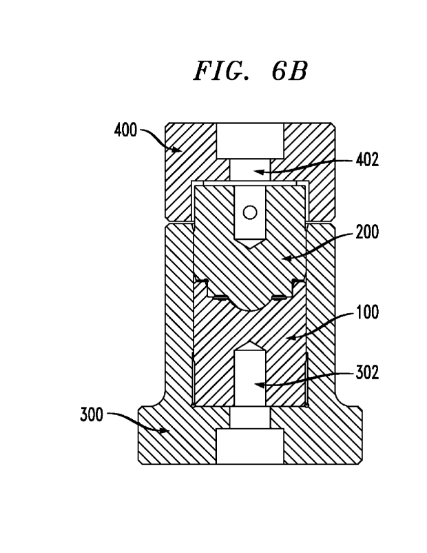
[0015] FIG. 6B is a cross-sectional view of the
mold assembly of FIG. 6A, according
to one or more illustrative embodiment&
[0016] FIG. 7 illustrates a contact lens with
excess material to be trimmed in a
secondary operation, according to one or more illustrative embodiment&
[0017] FIG. 8 illustrates a net shape lens,
according to one or more illustrative
embodiments.
DETAILED DESCRIPTION
[0018] This disclosure relates generally to direct
compression molded ophthalmic
devices such as soft contact lenses.
[0019] Exemplary embodiments will now be discussed
in further detail with regard to
direct compression molding of ophthalmic device forming polymers to form
ophthalmic
devices. The direct compression molding of one or more ophthalmic device
forming
polymers to form ophthalmic devices such as soft contact lenses advantageously
simplifies
the existing processes for making ophthalmic devices. For example, FIG. 1
shows a current
thermoset cast molding process 10 for making a soft contact lens. An
illustrative embodiment
shown in the method 10 of FIG 1 will now be described. In step 11,
polypropylene resin is
fed into an injection mold machine to form polypropylene pellets. In step 12,
the
polypropylene pellets are injected molded into anterior and posterior mold
halves. In step 13,
a monomer mixture is injected into the anterior mold. In step 14, the
posterior mold and
anterior mold are capped together. In step 15, the monomer mixture is cured
under typical
curing conditions to form the ophthalmic device. In step 16, the ophthalmic
device is
inspected for any irregularities or imperfections. In step 17, the
unpolymerized material is
extracted from the ophthalmic device. In step 18, the ophthalmic device is
then packaged in a
packaging system. For example, the ophthalmic device is transferred to an
individual lens
package containing a buffered saline solution containing optional additives as
known in the
art. Generally, a packaging system for the storage of an ophthalmic device
disclosed herein
includes at least a sealed container containing one or more of the ophthalmic
devices
immersed in an aqueous packaging solution. In one embodiment, the sealed
container is a
3
CA 03159708 2022-5-26
WO 2021/110512
PCT/EP2020/083373
hermetically sealed blister-pack, in which a concave well containing the
ophthalmic device is
covered by a metal or plastic sheet adapted for peeling in order to open the
blister-pack. The
sealed container may be any suitable generally inert packaging material
providing a
reasonable degree of protection to the lens, preferably a plastic material
such as polyalkylene,
PVC, polyamide, and the like. In step 19, the packaged ophthalmic device is
then sterilized.
Sterilization may take place prior to, or most conveniently after, sealing of
the container and
may be carried out by any suitable method known in the art, e.g., by steam
sterilizing or
autoclaving of the sealed container at temperatures of, for example, about 120
C or higher.
100201 FIG. 2, as described hereinbelow, shows a
direct compression molding process
for making an ophthalmic device such as a soft contact lens, according to an
illustrative
embodiment. As can be seen, the process shown in FIG. 2 advantageously
eliminates a
significant number of process steps as compared to the thermoset cast molding
process of
FIG. 1.
[0021] For example, the direct compression molding
process shown in FIG. 2
eliminates the monomer casting requirement into cast molds, curing, demolding
and
extraction to remove unreacted monomer and other impurities. In addition,
direct
compression molding of one or more ophthalmic device forming polymers
facilitates high
volume production of ophthalmic devices for modalities such as daily
disposable single use
lenses, e.g., in direct compression molding, the lens shape can be produced in
about 2 to about
3 seconds and does not require further post processing steps such as
extraction prior to
hydration and final packaging. This is due to the ophthalmic device forming
polymers as
discussed below being pre-formed such as a polymer film, a melt pellet and a
hot melt prior to
introducing it into the mold for direct compression molding into an ophthalmic
device. When
coupled with a continuous compression molding (CCM) process using, for
example, a rotary
compression molder, a high production rate can be achieved. In illustrative
embodiments,
rates from about 500 to about 2000 lenses per minute can be achieved as
compared to 100 to
300 lenses per minute for current cast molding processes.
[0022] As used herein, the terms "ophthalmic
device" and "lens" refer to devices that
reside in or on the eye. These devices can provide optical correction, wound
care, drug
4
CA 03159708 2022-5-26
WO 2021/110512
PCT/EP2020/083373
delivery, diagnostic functionality, cosmetic enhancement or any combination of
these
properties. Representative examples of such devices include, but are not
limited to, soft
contact lenses, e.g., soft, hydrogel lenses, soft, non-hydrogel lenses and the
like, intraocular
lenses, overlay lenses, ocular inserts, optical inserts, bandage lenses and
therapeutic lenses
and the like. As is understood by one skilled in the art, a lens is considered
to be "soft" if it
can be folded back upon itself without breaking. The ophthalmic devices such
as high water
content contact lenses of the illustrative embodiments can be spherical,
tonic, bifocal, and may
contain cosmetic tints, opaque cosmetic patterns, combinations thereof and the
like.
100231 Suitable ophthalmic device forming polymers
for direct compression molding
include, for example, hydrophilic thermoplastic polyurethanes (h-TPU) such as
aliphatic and
aromatic hydrophilic thermoplastic polyurethanes and polyesters, blends of the
polyurethanes
or polyesters with hydrophobic silicones and/or oligomers or polymers thereof
In illustrative
embodiments, the foregoing ophthalmic device forming polymers can exhibit (a)
water
contents from about 10% to about 90%, or from about 40% to about 80%, (b) a
hydrated
modulus less than about 100 g/mm2, (c) a captive bubble contact angle from
about 300, to
about 900, or less than about 50 , e.g., from about 30 to less than about 500,
(d) visible light
transmission from about 65% to about 100%, or greater than about 90% and (e) a
refractive
index from about 1.35 to about 1.50.
100241 Suitable aliphatic hydrophilic
thermoplastic polyurethanes include, for
example, those obtained from a reaction product of an aliphatic organic
diisocyanate, a
hydroxyl-terminated polyol and a low molecular weight glycol (chain extender)
in the
presence of a catalyst. In general, the polyurethanes are a condensation
product of a reaction
between one or more diisocyanates and compounds containing active hydrogen
sites such as
hydroxyl groups. The diisocyanate can be an isocyanate compound having a
functionality of
two. Examples of suitable aliphatic polyisocyanates include isophorone
diisocyanate (1PDI),
1,4-cyclohexyl diisocyanate (CHDI), decane-1,10-diisocyanate, lysine
diisocyanate (LDI),
1,4-butane diisocyanate (BDI), 1,5-pentanediisocyanate (PDI), hydrogenated
xylene
diisocyanate (11:XDI), isophorone diisocyanate, hexamethylene diisocyanate
(HDI) and
dicyclohexylmethane-4,4'-diisocyanate (H12MDI). Mixtures of two or more
polyisocyanates
CA 03159708 2022-5-26
WO 2021/110512
PCT/EP2020/083373
may be used. In one embodiment, a suitable diisocyanate is dicyclohexylmethane
diisocyanate (HIMDI).
[0025] Any hydroxyl terminated polyol can be used
in herein. Suitable polyols
include polyether polyols, polyester polyols, polycarbonate polyols,
polysiloxane polyols, and
combinations thereof In one illustrative embodiment, the hydroxyl terminated
polyol
comprises a polyether polyol. Hydroxyl terminated polyether polyols include
polyether
polyols derived from a diol or polyol having a total of from 2 to 15 carbon
atoms. In some
embodiments, hydroxyl terminated polyether polyols include polyether polyols
derived from
an alkyl diol or glycol which is reacted with an ether comprising an alkylene
oxide having
from 2 to 6 carbon atoms, typically ethylene oxide or propylene oxide or
mixtures thereof
For example, hydroxyl functional polyether can be produced by first reacting
propylene
glycol with propylene oxide followed by subsequent reaction with ethylene
oxide. Primary
hydroxyl groups resulting from ethylene oxide are more reactive than secondary
hydroxyl
groups and thus are preferred. Useful commercial polyether polyols include
poly(ethylene
glycol) comprising ethylene oxide reacted with ethylene glycol, poly(propylene
glycol)
comprising propylene oxide reacted with propylene glycol, poly(tetramethylene
ether glycol)
comprising water reacted with tetrahydrofuran which can also be described as
polymerized
tetrahydrofuran., and which is commonly referred to as PTIvIEG.
[0026] Polyether polyols also include polyamide
adducts of an alkylene oxide and can
include, for example, ethylenediamine adduct comprising the reaction product
of
ethylenediamine and propylene oxide, diethylenetriamine adduct comprising the
reaction
product of diethylenetriamine with propylene oxide, and similar polyamide type
polyether
polyols. Copolyethers can also be utilized in the described compositions.
Typical
copolyethers include the reaction product of THF and ethylene oxide or THF and
propylene
oxide. These are available from BASF as PolyTHF B, a block copolymer, and
PolyTHFOD
R, a random copolymer. The various polyether intermediates generally have a
number
average molecular weight (Mn) as determined by assay of the terminal
functional groups
which is an average molecular weight greater than about 700, such as from
about 700 to about
10,000, or from about 1,000 to about 8,000, or from about 1,400 to about
8,000.
6
CA 03159708 2022-5-26
WO 2021/110512
PCT/EP2020/083373
[0027]
In one embodiment, any high
molecular weight polyether polyol available to
one of ordinary skill in the art can be used herein. In one embodiment, a high
molecular
weight polyether polyol is one having an average molecular weight between
about 500 and
about 5000. In an illustrative embodiment, a suitable high molecular weight
polyether polyol
is polytetramethylene ether glycol (PTMEG). In an illustrative embodiment,
PTMEG has an
average molecular weight of about 1000 to about 2000.
[0028]
Suitable low molecular weight
glycols include, for example, lower aliphatic or
short chain glycols having from 2 to 20, or 2 to 12, or 2 to 10 carbon atoms.
Representative
examples of low molecular weight glycols include ethylene glycol, diethylene
glycol,
propylene glycol, dipropylene glycol, 1,4-butanediol (BDO), 1,6-hexanediol
(HDO), 1,3-
butanediol, 1,5-pentanediol, neopentylglyeol, 1,4-eyelohexanedimethanol
(CHDM), 2,2-
bis[4-(2-hy droxyethoxy) phenyl]propane (HEPP), hexamethylenediol,
heptanediol,
nonanediol, dodecanediol, 3-methyl-1,5-pentanediol, ethylenediamine,
butanediamine,
hexamethylenediamine, and hydroxyethyl resorcinol (HER), and the like, as well
as mixtures
thereof.
[0029]
One or more polymerization
catalysts may be present during the
polymerization reaction. Generally, any conventional catalyst can be utilized
to react the
diisocyanate with the hydroxyl terminated polyol or the chain extender.
Examples of suitable
catalysts include tertiary amines, e.g. triethylamine,
dimethylcyclohexylamine, N-
methylmorpholine, N,N'-dimethylpiperazine,
2-
(dimethylaminoethoxy)ethanol,
diazabicyclo[2.2.2]octane and the like, organometallic compounds, such as
titanic esters, iron
compounds, e.g. ferric acetylacetonate, tin compounds, e.g. stannous
diacetate, stannous
dioctoate, stannous dilaurate, or the dialkyltin salts of aliphatic carboxylic
acids, e.g.
dibutyltin diacetate, dibutyltin dilaurate, or the like. The amounts usually
used of the catalysts
are from 0.0001 to 0.1 part by weight per 100 parts by weight of polyhydroxy
compound (b).
[0030]
In order to prepare a
hydrophilic thermoplastic polyurethane, the three
reactants (the polyol, the diisocyanate, and the chain extender) may be
reacted together to
form the hydrophilic thermoplastic polyurethane. Any known processes to react
the three
reactants may be used to make the TPU. In one embodiment, the process is a so-
called "one-
7
CA 03159708 2022-5-26
WO 2021/110512
PCT/EP2020/083373
shot" process where all three reactants are added to an extruder reactor and
reacted. The
equivalent weight amount of the diisocyanate to the total equivalent weight
amount of the
hydroxyl containing components, that is, the polyol intermediate and the chain
extender
glycol, can be from about 0.95 to about 1.10, or from about 0.96 to about
1.02, and even from
about 0.97 to about 1.005. Reaction temperatures utilizing a urethane catalyst
can be from
about 175 to about 245 C.
[0031] The hydrophilic thermoplastic polyurethane
can also be prepared utilizing a
pre-polymer process. In the pre-polymer route, the polyol is reacted with
generally an
equivalent excess of one or more diisocyanates to form a pre-polymer solution
having free or
unreacted diisocyanate therein. The reaction is generally carried out at
temperatures of from
about 80 to about 220 C in the presence of a suitable urethane catalyst.
Subsequently, a chain
extender, as noted above, is added in an equivalent amount generally equal to
the isocyanate
end groups as well as to any free or unreacted diisocyanate compounds. The
overall
equivalent ratio of the total diisocyanate to the total equivalent of the
polyol intermediate and
the chain extender is thus from about 0.95 to about 1.10, or from about 0.96
to about 1.02 and
even from about 0.97 to about 1.05. The chain extension reaction temperature
is generally
from about 180 to about 250 C.
[0032] In general, aliphatic hydrophilic
thermoplastic polyurethanes for use herein can
be those described in, for example, U.S. Patent No. 4,523,005 and G.
Verstraete et. al.,
"Hydrophilic thermoplastic urethanes for the manufacturing of highly dosed
oral sustained
release matrices via hot melt extrusion and injection molding," Int 7 Pharm.,
506 (1-2):214-
21) (2016), the contents of which are incorporated by reference herein. These
polyurethanes
include a soft segment (SS) based on, for example, a polyethylene oxide (PEO)
and a hard
segment (HS) based on, for example, hexamethylene diisocyanate (UNIDO in
combination
with 1,4-butanediol (1,4-BD) as a chain extender with a SS/HR ratio greater
than about 30,
e.g., from about 40 to about 85. In one embodiment, these polyurethanes can
exhibit a water
content of from about 60 to about 90%. Suitable aliphatic hydrophilic
thermoplastic
polyurethanes are commercially available under the tradename Tecophilic
(Lubrizol
8
CA 03159708 2022-5-26
WO 2021/110512
PCT/EP2020/083373
Corporation), e.g., Tecophilic TG-500 (also referred to as "TG-500") and
Tecophilic TG-2000
(also referred to as "TG-2000").
[0033]
It is also contemplated that
h-TPU's with the above or similar hard and soft
segments at differing ratios less than 30 can be used that exhibit lower water
contents such as
from about 5 to about 25. Suitable thermoplastic polyurethanes include those
commercially
available under the tradename Tecophilic (Lubrizol Corporation). Examples of
such h-TPU's
include those commercially available under such tradenames as Hydrothane
(AdvancSource
Biomaterials Corporation), e.g., Hydrothane AL, 25-80A that exhibits a water
content of 25%.
[0034]
For the aromatic hydrophilic
thermoplastic polyurethanes, suitable aromatic
organic diisocyanate compounds that can be used include, for example,
methylene diphenyl
diisocyanate (MDI), 4,4'-diphenylmethane diisocyanate, p-phenylene
diisocyanate, xylene
diisocyanate, hexamethylene diisocyanate, isophorone diisocyanate, tolylene
diisocyanate,
1,5-naphthalene diisocyanate, and 4,4'-dicyclohexylmethane diisocyanate.
[0035]
In some illustrative
embodiments, these h-TPU's can exhibit haze and
translucency when hydrated. To obtain a desired water content and improve
their
clarity/reduce haze, these TPU's may be melt compounded with other hydrophobic
materials
and polymers.
[0036]
In one illustrative
embodiment, blends of ophthalmic device forming polymers
such as the foregoing h-TPU's with optically clear thermoplastics polymers can
be used for
forming direct compression ophthalmic devices. Suitable thermoplastics
polymers include,
for example, polymethyl methacrylate, cyclic olefin polymers, produced by
chain
copolymerization of cyclic monomers such as 8,9,10-trinorborn-2-ene
(norbornene) or
1,2 ,3 ,4,4a, 5,8,8a-octa hydro-1 ,4 :5,8
ethanonaphthalene (tetracy
clod odecene) with ethene,
e.g., those available under such tradenames as TOPAS (Advanced Polymer) and
APEL
(Mitsui Chemical), or by ring-opening metathesis polymerization of various
cyclic monomers
followed by hydrogenation, e.g., those available under such tradenames as
ARTON (Japan
Synthetic Rubber), and Zeonex and Zeonor (Zeon Chemical) (see, e.g., Pure
Appl. Chem.,
Vol. 77, No. 5, pp. 801-814, (2005), the contents of which are incorporated by
reference
herein), a cyclic block copolymer comprising a styrenic block copolymer such
as styrene-b-
9
CA 03159708 2022-5-26
WO 2021/110512
PCT/EP2020/083373
butadiene-b-styrene (SBS) and styrene-b-isoprene-b-styrene (SIS) with a
hydrogenation level
of >99.5% (see, e.g., Inventions 2018, 3(3), 49), the contents of which are
incorporated by
reference herein), commercially available under the tradename CBC Vivion ([IS!
Corporation, Kaohsiung City, Taiwan), a styrene acrylonitrile commercially
available under
the tradename Luran (Sryrolution), a polyethylene terephthalate-glycol PET-g
commercially
available under the tradename Xcel (Artenius) and polylactic acid.
[0037]
In one illustrative
embodiment, blends of ophthalmic device forming polymers
such as the foregoing h-TPU's with silicone polymers can be used for forming
direct
compression ophthalmic devices.
Suitable silicone polymers
include, for example,
polydimethylsiloxane or dimethicone both commercially available from Dow,
Momentive or
Clearco Products. Representative examples of such polydimethylsiloxanes
include PDMS
Silicone Oil (Clearco Products) with a viscosity ranging from about 300,000 to
about
20,000,000 cSt, Cyclo-1500 Dimethiconol-Cyclopentasiloxane blend and
decamethylcyclopentasiloxane silicone oils such as Cyclo-2244, Cyclo-2245 and
Cyclo-2345
Cyclomethicone Fluids (Clearco Products).
[0038]
In one illustrative
embodiment, blends of ophthalmic device forming polymers
such as the foregoing h-TPU's with silicone-urethane copolymers can be used
for forming
direct compression ophthalmic devices. Suitable silicone-urethane copolymers
include, for
example, those commercially available under the tradename PurSil (DSM) and
Quadrasil
(Biomerics). See, also U.S. Patent No. 5,589,563, the contents of which are
incorporated by
reference herein. These are polydimethylsiloxanes incorporated into the
polymer soft
segment with polytetramethyleneoxide (PTMO) and a hard segment of an aromatic
diisocyanate, e.g., 4,41-methylene-diphenyldiisocyanate (MD!), with a low
molecular weight
glycol chain extender. The copolymer chains are terminated with silicone or a
similar
functional group.
[0039]
In one illustrative
embodiment, blends of ophthalmic device forming polymers
such as the foregoing h-TPU's with transparent amorphous polyamides can be
used for
forming direct compression ophthalmic devices. Suitable s amorphous
polyarnides include,
for example, those made from dimethyl terephthalate and trimethylhexamethylene
diamine
CA 03159708 2022-5-26
WO 2021/110512
PCT/EP2020/083373
monomers under the tradename Trogamid T (Evonik Industries), and amorphous
polyamides
made from a cycloaliphatic diamine and 1,12-dodecanedioic acid monomer under
the
tradename Trogamid CX (Evonik Industries), and amorphous polyamides made from
2,2`-
dimethy1-4,4`-methylenebis(cyclohexylamine) and dodecanedioic acid monomers
under the
tradename EMS Grivory TR from EMS-CHEMEE (Sumter).
[0040] In one illustrative embodiment, additional
suitable ophthalmic device forming
polymers include partially or "lightly" cross-linked thermoplastic. In one
embodiment,
additional suitable ophthalmic device forming polymers include partially cross-
linked TPU's
created by thermoplastic vulcanizate (TPV) dynamic vulcanization. Dynamic
vulcanization
has been applied to the vulcanization of the soft elastomer phase of a blend
with rigid
thermoplastics. The process is carried out under high shear and above the
melting point of the
thermoplastic at sufficiently high temperature to activate and complete the
vulcanization.
See, for example, "The Effect of Dynamic Vulcanization on the Properties of
Polypropylene/Ethylene-Propylene Diene Terpolymer/ Natural Rubber (PP/EPDM/NR)
Ternary Blend," Halimatuddahliana et. al., Polymer-Plastics Technology and
Engineering,
Volume 48, 2008 - Issue 1.
[0041] In one embodiment, additional suitable
ophthalmic device forming polymers
include partially cross-linked TPU's that are created by electron beam
crosslinking.
[0042] In one embodiment, additional suitable
ophthalmic device forming polymers
include partially cross-linked TPU's such as those described in U.S. Patent
No. 4,666,781, the
contents of which are incorporated by reference herein. For example, partially
cross-linked
TPU's can be those linear thermoplastic polyurethane with acry late side and
terminal groups
wherein the polyurethane is prepared by reacting poly- and/or diisocyanates
with a mixture of
(a) methacrylate- or acrylate-diols, (b) monoesters of methacrylic or acrylic
acid and a diol
and other organic polydiol compounds. In one embodiment, the partially cross-
linked TPU's
can be prepared by reacting poly- and/or diisocyanates with a mixture of (a)
methacrylate- or
acrylate-diols having molecular weights of from about 146 to about 3,000, (b)
monoesters of
methacrylic or acrylic acid and a diol having a molecular weight of from about
116 to about
300, and (c) other organic polydiol compounds which have molecular weights of
from about
11
CA 03159708 2022-5-26
WO 2021/110512
PCT/EP2020/083373
400 to about 5,000 and differ from (a), with or without (d) diols which differ
from (a),
diamines, aminoalcohols or triols having molecular weights of from about 61 to
about 400, or
water, in an NCO/OH ratio of from about 0.9:1 to about 1.1:1, with the proviso
that from
about 1.4 to about 10 moles of poly and/or diisocyan,ate, from about 0.1 to
about 6 moles of
components (a) and (b) and, where relevant, not more than about 9 moles of
component (d)
are used per mole of component (c).
[0043] In one embodiment, additional suitable
ophthalmic device forming polymers
include partially cross-linked TPU's such as those described in U.S. Patent
No. 6,444,721, the
contents of which are incorporated by reference herein. For example, lightly
cross-linked
TPU's can be those water dispersible radiation curable polyurethane composed
essentially of
aliphatic polyisocyanates, cycloaliphatic diols and/or diamines, compounds and
at least one
free-radically polymerizable unsaturated group.
[0044] In one embodiment, additional suitable
ophthalmic device forming polymers
include partially cross-linked TPU's such as those described in U.S. Patent
No. 8,168,260, the
contents of which are incorporated by reference herein. For example, partially
cross-linked
TPU's can include a reaction system comprising (a) a polyfunctional
isocyanate; (b) a
polyfunctional polyol; (c) a diol chain extender; and (d) a monol or monoamine
comprising
radically polymerizable unsaturation; or a prepolymer thereof In one
embodiment, the
partially cross-linked TPU's can include a modified prepolymer comprising (a)
a
polyfunctional isocyanate; (b) a polyfunctional polyol; and (c) a monol or
monoamine
comprising radically polymerizable unsaturation, optionally with a radically
polymerizable
co-crosslinker. The amount of monol may be such that the molecular weight (MW)
(measured as number average Mn) of the final TPU can be comprised of between
about
12,000 and about 500,000, or between about 20,000 and about 200,000. The
amount of
monol is typically from about 0.001 moles/100 g to about 0.016 moles/100 g, or
from about
0.002 moles/100 g to about 0.01 moles/100 g of the polymer composition. The
monol acts
usually as a chain stopper so that the MW can be controlled.
[0045] In one illustrative embodiment, other
ophthalmic device forming polymers
such as hydrophilic thermoplastic materials that can be used herein that form
hydrogels
12
CA 03159708 2022-5-26
WO 2021/110512
PCT/EP2020/083373
include, for example, sulfonated polysulfones (s-PSU), agarose,
methylcellulose, hyaluronan
and tropoelastin protein.
[0046] In direct compression molding, the
ophthalmic device forming polymer can be
in such forms as, for example, a polymer film, a melt pellet or a hot melt
Each of the forms
will be discussed as follows.
[0047] Films ¨ a material film can be prepared by
the following two methods: (i) film
extrusion or (ii) compression molding. In the case of film extrusion, material
pellets of the
ophthalmic device forming polymers are fed into an extruder and the molten
material is
forced through a slit die and cooled into a film. In the case of compression
molding, material
pellets of the ophthalmic device forming polymers are melted at a temperature
between about
100 to about 150 C in a single or twin-screw extruder or co or counter
rotating heated kneader
(such as a Banbury or Brabender mixer). In this process, the melt is extruded
onto a plate,
then capped with a second plate and pressed in a heated Carver press at about
135 C under
7000 psi for approximately 10 minutes to produce a film thickness of about 200
to about 1000
microns. A relatively small portion, for example, approximately 10 x 10 mm, of
this film is
then placed onto the bottom cavity of the mold machine. The top cavity is then
aligned and
pressed down onto the film forming the lens.
[0048] Melt pellets ¨ Melt pellets can be prepared
by melting the material pellets of
the ophthalmic device forming polymers in a single screw extruder and then
forced through
an orifice that is approximately 25% smaller than the desired diameter of the
melt pellet.
When the material extrudes from the orifice, a die face knife is used to cut
the molten ball of
material. In this way a melt pellet is produced and can be delivered into the
molding cavity
for subsequent compression molding into a lens.
[0049] Hot melt ¨ In this process, the material
pellets are melted in an extruder or
heated cylinder and the melt is then forced through an orifice approximately
about 0.1 to
about 2 mm in diameter (preferably about 0.5 to about 1 mm in diameter) using
either a piston
or compressed air. This produces a small melt bead that is directly dropped or
sprayed onto
the mold cavity followed by subsequent compression molding into a lens.
13
CA 03159708 2022-5-26
WO 2021/110512
PCT/EP2020/083373
[0050] In general, direct compression molding of
ophthalmic devices such as soft
contact lenses involves one or more ophthalmic device forming polymers such as
hydrophilic
thermoplastic melt processable polymers, mold tooling, heat and compression of
the mold
tools (see, FIGs. 4-6B). In one illustrative embodiment, a direct compression
molding process
30 as illustrated in FIG. 3, involves, in steps 31 and 32, charging a
preheated concave (or
anterior) metal compression mold half with one or more of polymer pellets,
films or polymer
melts as discussed above. In step 33, the concave (or anterior) metal
compression mold half
is capped with a convex (or posterior) metal compression mold half in a
vertical axis. In an
alternative embodiment, the step of charging can be reversed or conducted in a
horizontal
axis. Optical mold tooling can be designed as either net shape or contain
features that create
additional materials around the perimeter of the lens that can be subsequently
trimmed in a
secondary process.
[0051] In one embodiment, a heated mold assembly
comprising a concave metal
compression mold half, one or more ophthalmic device forming polymers such as
a
hydrophilic thermoplastic melt processable polymer(s) and a convex metal
compression mold
half can be compressed under pressure for a time period ranging from about 0.5
seconds to
about 5 minutes as shown in steps 34 and 35. In another embodiment, a heated
mold
assembly comprising a concave metal compression mold halt one or more
ophthalmic device
forming polymers such as a hydrophilic thermoplastic melt processable
polymer(s) and a
convex metal compression mold half can be compressed under pressure for a time
period
ranging from about 30 seconds to about 120 seconds. In general, the mold
assembly can be
heated to a temperature ranging from about 50 to about 200 C. In one
embodiment, the mold
assembly can be heated to a temperature ranging from about 120 to about 150 C.
Next, the
mold assembly can be cooled in step 36, and then subsequently separated in
step 37. The
finished shape or device is extracted by, for example, hydrating the lens off
the anterior mold
half Hydration of the device such as a contact lens results in a soft contact
lens. This lens
has the advantage that it does not require any extraction and may be directly
hydrated prior to
packaging.
14
CA 03159708 2022-5-26
WO 2021/110512
PCT/EP2020/083373
[0052] Suitable tooling for the direct compression
molding process of the one or more
ophthalmic device forming polymers include, for example, optical mold tooling
with a surface
roughness (Li or RMS) less than about 100 nanometers with tools forming the
posterior and
anterior surfaces simultaneously. Representative examples of mold tooling used
in a
compression molding process include (i) a single cavity-core tooling
compressed in a heated
press, (ii) a multi-cavity tooling compressed in a heated press and (iii) a
rotary continuous
compression molding machine (CCM) such as those manufactured by SACML
[0053] A representative mold tool assembly for
compression molding of ophthalmic
devices such as contact lenses according to illustrative embodiments herein is
shown in FIGS.
4 to 6B. In general, a mold tool assembly includes a first mold tool section
and a second mold
tool section. As shown in FIG. 4, a first mold tool section includes an
anterior metal
compression mold half 100 without or without a lens trim feature (not shown)
and having a
concave surface. The anterior metal compression mold half 100 includes an
optical quality
anterior lens-molding surface 102 for forming the contact lens anterior
surface. As shown in
FIG. 5, the second mold tool section includes a posterior metal compression
mold half 200
having a convex surface. The posterior metal compression mold half 200
includes an optical
quality posterior lens-molding surface 202 for forming the contact lens
posterior surface. The
anterior metal compression mold half 100 and posterior metal compression mold
half 200 can
be formed of, for example, a copper-based alloy or steel. In addition, as one
skilled in the art
will readily appreciate, the mold cavity surface, i.e., when the mold sections
are fully
assembled, a lens-forming cavity (not shown) is defined between lens-molding
surfaces, for
each of the anterior metal compression mold half 100 and the posterior metal
compression
mold half 200 can be plated with a ceramic coating material such as a DLC
(diamond-like
coating) to assist in releasing the resulting ophthalmic device from the mold
assembly.
[0054] As shown in FIGs. 6A and 6B, in operation,
the bottom portion of anterior
metal compression mold half 100 is placed in tool holder 300 such that optical
quality anterior
lens-molding surface 102 is face up. For example, anterior metal compression
mold half 100
can be operatively connected to tool holder 300 by way of, for example, screw
302.
However, as one skilled in the art will appreciate, other ways to operatively
connect anterior
CA 03159708 2022-5-26
WO 2021/110512
PCT/EP2020/083373
metal compression mold half 100 to tool holder 300 are contemplated. Posterior
metal
compression mold half 200 is then operatively connected to anterior metal
compression mold
half 100 such that optical quality posterior lens-molding surface 202 is
disposed in the
opening in optical quality anterior lens-molding surface 102 defining a lens-
forming cavity.
Prior to operatively connecting posterior metal compression mold half 200 with
anterior metal
compression mold half 100, the ophthalmic device forming polymers in the form
of a
substantially thermoplastic polymer film, melt pellet or hot melt as discussed
above is
disposed in the opening defining optical quality anterior lens-molding surface
102 of anterior
metal compression mold half 100 in tool holder 300. This is one illustrative
embodiment and
other embodiments for connecting posterior metal compression mold half 200
with anterior
metal compression mold half 100, and introducing the one or more ophthalmic
device
forming polymers into the assembly are contemplated.
[0055] Once assembled, posterior metal compression
mold half 200 and anterior metal
compression mold half 100 are aligned. The mold assembly is then compressed
for a time
period sufficient to form an ophthalmic device as discussed above. After the
compression is
completed, extraction tool 400 is placed over posterior metal compression mold
half 200 and
screw 402 is turned until the posterior metal compression mold half 200 is
separated from
anterior metal compression mold half 100. Next, the resulting ophthalmic
device is removed
from the anterior metal compression mold half 100 by, for example, hydrating
the ophthalmic
device with water or a suitable solution and removing it by tweezers.
[0056] The foregoing tool assembly can produce,
for example, a +3.00 hydrated SVS
lens with an 8.5 Base Curve, a center thickness of 160 microns, a nominal lens
sag of 3.987
mm and a knife edge profile. In an illustrative embodiment, based on the
anterior surface
tool, a lens with extra material around the lens perimeter can be produced
(see, HG. 7) which
can be trimmed in a secondary operation, or a net shape lens can be produced
(see, FIG. 8).
[0057] An illustrative embodiment shown in the
method 20 of FIG 2 will now be
described. In step 21, the one or more ophthalmic device forming polymers are
fed into an
extruder to form pellets. In step 22, the pellets are introduced into a mold
and subjected to
continuous direct compression molding to form ophthalmic devices. In step 23,
each
16
CA 03159708 2022-5-26
WO 2021/110512
PCT/EP2020/083373
ophthalmic device is optionally trimmed/punched to achieve a desired edge
geometry. In step
24, each ophthalmic device is inspected for any irregularities or
imperfections. In step 25, if
the ophthalmic device passes inspection it is then hydrated, removed from the
assembly and
packaged in a packaging system. For example, the ophthalmic device is
transferred to an
individual lens package containing a buffered saline solution containing
optional additives as
known in the art. Generally, a packaging system for the storage of an
ophthalmic device
disclosed herein includes at least a sealed container containing one or more
of the ophthalmic
devices immersed in an aqueous packaging solution. In one embodiment, the
sealed container
is a hermetically sealed blister-pack, in which a concave well containing the
ophthalmic
device is covered by a metal or plastic sheet adapted for peeling in order to
open the blister-
pack. The sealed container may be any suitable generally inert packaging
material providing
a reasonable degree of protection to the lens, preferably a plastic material
such as
polyalkylene, PVC, polyamide, and the like. Any known buffered saline solution
can be used
herein. In step 26, the packaged ophthalmic device is then sterilized.
Sterilization may take
place prior to, or most conveniently after, sealing of the container and may
be carried out by
any suitable method known in the art, e.g., by steam sterilizing or
autoclaving of the sealed
container at temperatures of, for example, about 120 C or higher.
[0058] The following examples are provided to
enable one skilled in the art to practice
the invention and are merely illustrative. The examples should not be read as
limiting the
scope of the invention as defined in the claims.
[0059] Various lenses were formed as discussed
below and may be characterized by
standard testing procedures such as:
[0060] Water %: Two sets of six hydrated lenses or
films are blotted dry on a piece of
filter paper to remove excess water, and samples are weighed (wet weight).
Samples are then
placed in a microwave oven for 10 minutes inside ajar containing desiccant.
The samples are
then allowed to sit for 30 minutes to equilibrate to room temperature and
reweighed (dry
weight). The percent water is calculated from the wet and dry weights.
[0061] Contact Angle (CBCA): Captive bubble
contact angle data was collected on a
First Ten Angstroms FTA-1000 drop Shape Instrument All samples were rinsed in
HPLC
17
CA 03159708 2022-5-26
WO 2021/110512
PCT/EP2020/083373
grade water prior to analysis in order to remove components of the packaging
solution from
the sample surface. Prior to data collection, the surface tension of the water
used for all
experiments was measured using the pendant drop method. In order for the water
to qualify
as appropriate for use, a surface tension value of 70 to 72 dynes/cm was
expected. All lens
samples were placed onto a curved sample holder and submerged into a quartz
cell filled with
HPLC grade water. Advancing and receding captive bubble contact angles were
collected for
each sample. The advancing contact angle is defined as the angle measured in
water as the air
bubble is retracting from the lens surface (water is advancing across the
surface). All captive
bubble data was collected using a high-speed digital camera focused onto the
sample/air
bubble interface. The contact angle was calculated at the digital frame just
prior to contact
line movement across the sample/air bubble interface. The receding contact
angle is defined
as the angle measured in water as the air bubble is expanding across the
sample surface (water
is receding from the surface).
EXAMPLE 1
[0062] A compression molded lens was prepared by a
single net shape cavity-core
tooling compressed in a heated press. The concave anterior, convex posterior
and tool holder
were heated in an oven at 175 C for 10 minutes. A Tecophilic TG-500 (Lubrizol
Life
Science, Brecksville, OH) film approximately 10 x 10 mm square and 100 microns
thick,
prepared as discussed hereinabove, was charged on the concave anterior tool
held in a tool
holder that served to hold and align the posterior tool over the anterior
tool. The posterior
tool was assembled over the anterior tool in the tool holder. This assembly
was heated in an
oven for 5 minutes at 175 C. The assembly was removed from the oven and
immediately
placed in a press whose platens have been heated to 150 C. The assembly was
compressed
for 30 seconds, and then the assembly was removed from the press and cooled in
a water bath
to 28 C. Next, the posterior tool was removed, and the finished lens was
extracted using
tweezers from the anterior tool. The lens was hydrated in a borate buffer
solution. The lens
properties such as power, center thickness and diameter were measured as set
forth below in
Table 1.
18
CA 03159708 2022-5-26
WO 2021/110512
PCT/EP2020/083373
EXAMPLE 2
[0063] A compression molded lens was prepared by a
single net shape cavity-core
tooling compressed in a heated press. The concave anterior, convex posterior
and tool holder
were heated in an oven at 175 C for 10 minutes. A TG-500 film approximately 10
x 10 mm
square and 100 microns thick, prepared as discussed hereinabove, was charged
on the concave
anterior tool held in a tool holder that served to hold and align the
posterior tool over the
anterior tool. The posterior tool was assembled over the anterior tool in the
tool holder. This
assembly was heated in an oven for 10 minutes at 175 C. The assembly was
removed from
the oven and immediately placed in a press whose platens have been heated to
150 C. The
assembly was compressed for 60 seconds, and then removed from the press and
cooled in a
water bath to 23 C. Next, the posterior tool was removed, and the finished
lens was hydrated
with distilled water and extracted with tweezers. The lens was hydrated in a
borate buffer
solution. The lens properties such as power, center thickness and diameter
were measured as
set forth below in Table 1.
EXAMPLE 3
[0064] A compression molded lens was prepared by a
single net shape cavity-core
tooling compressed in a heated press. The concave anterior, convex posterior
and tool holder
are heated in an oven at 175 C for 10 minutes. A TG-500 film approximately 10
x 10 mm
square and 100 microns thick, prepared as discussed hereinabove, was charged
on the concave
anterior tool held in a tool holder that served to hold and align the
posterior tool over the
anterior tool. The posterior tool was assembled over the anterior tool in the
tool holder. This
assembly was heated in an oven for 10 minutes at 175 C. The assembly was
removed from
the oven and immediately placed in a press whose platens have been heated to
150 C. The
assembly was compressed for 120 seconds, and then removed from the press and
cooled in a
water bath to 27 C. Next, the posterior tool was removed, and the finished
lens was hydrated
with distilled water and extracted with tweezers. The lens was hydrated in a
borate buffer
solution. The lens properties such as power, center thickness and diameter are
set forth below
in Table 1.
19
CA 03159708 2022-5-26
WO 2021/110512
PCT/EP2020/083373
TABLE 1
Example 1
Example 2 Example 3
Material Tecophilic TG-500
Tecophilic TG-500 Tecophilic TG-500
Material Form 100 pm film 100
pm film 100 pm film
Tooling Net shape tool Net
shape tool Net shape tool
Lens Type SVS SVS
SVS
Aim Power (D) +3.00
+3.00 +3.00
Actual Power' (D) +3.25
+2.75 +2.75
Diameter2
14.2001>15
14.2001>15 14.2001>15
Aim/Actual (mm)
Center Thickness
0.160/ 0.187
0.160 / 0.144 0.160 / 0.156
Aim/Actual (mm)
1 Vertexometer Power ¨ 15 mm paddle used.
2 Diameter inferred based on 15 mm paddle used for the Vertexometer
measurement.
EXAMPLE 4
100651 A compression molded lens was prepared by a
single net shape cavity-core
tooling compressed in a heated press. The concave anterior, convex posterior
and tool holder
were heated in an oven at 160 to 175 C for 10 minutes. A Tecophilic TG-500
film
approximately 10 x 10 mm square and 100 microns thick, prepared as described
hereinabove,
was charged on the concave or anterior tool held in a tool holder that served
to hold and align
the posterior tool over the anterior tool_ The posterior tool was assembled
over the anterior
tool in the tool holder. This assembly was heated in an oven for 10 minutes at
160 to 175 C.
The assembly was removed from the oven and immediately placed in a press whose
platens
were heated to 150 C. The assembly was compressed for 60 seconds, and then
removed from
the press and cooled in a water bath to 25 C. Next, the posterior tool was
removed, and the
finished lens was hydrated with distilled water and extracted with tweezers.
The lens was
then hydrated in a borate buffer solution. The lens properties such as power,
center thickness
and diameter were measured as set forth below in Table 2. Three lenses were
prepared by this
method.
CA 03159708 2022-5-26
WO 2021/110512
PCT/EP2020/083373
EXAMPLE 5
[0066] A compression molded lens was prepared by a
single net shape cavity-core
tooling compressed in a heated press. The concave anterior, convex posterior
and tool holder
were heated in an oven at 160 to 175 C for 10 minutes._ A Tecophilic TG-500
plus + 20%
Hydrothane AL 25-80A (elastomeric hydrophilic TPU with an 80 Shore A hardness,
25%
water content from AdvancSource Biomaterials Corporation, Wilmington, MA)
film,
prepared as described hereinabove, was charged on the concave or anterior tool
held in a tool
holder that served to hold and align the posterior tool over the anterior
tool. The posterior
tool was assembled over the anterior tool in the tool holder. This assembly
was heated in an
oven for 10 minutes at 160 to 175 C. The assembly was removed from the oven
and
immediately placed in a press whose platens were heated to 150 C. The assembly
was
compressed for 60 seconds, and then removed from the press and cooled in a
water bath to
25 C. Next, the posterior tool was removed, and the finished lens was hydrated
with distilled
water and extracted with tweezers. The lens was then hydrated in a borate
buffer solution.
The film thickness and lens properties such as power, center thickness and
diameter are set
forth below in Table 2. Three lenses were prepared by this method.
21
CA 03159708 2022-5-26
WO 2021/110512
PCT/EP2020/083373
TABLE 2
Example 4
Example 5
Tec,ophilic TG-500 + 20%
Material Tecophilic TG-500
AdvanSource Hydrothane AL 25-80A
Material Form 327 pm film
293 gm film
Tooling Net shape tool
Net shape tool
Lens Type SVS
SVS
Aim Power (D) +3.00
+3.00
Power' (D) / St. Dev. +2.75 (-)
+2.67 (0.29)
Image quality Fair
Good
Diameter2 Aim/Actual
14.200/>15
14.200/>15
(mm)
Center Thickness 0.160 /
0.160 /
Aim/Actual (mm) 0.157 (0.001)
0.154 (0.006)
Water Content (%) 78.4
73.1
X-Y Expansion factor 1.83
1.67
1 Vertexometer Power ¨ 15 mm paddle used.
2 Diameter inferred based on 15 mm paddle used for the Vertexometer
measurement.
EXAMPLES 6-9
[0067] A compression molded lens was prepared by a
single net shape cavity-core
tooling compressed in a heated press. The concave anterior, convex posterior
and tool holder
were heated in an oven at 160 to 175 C for 10 minutes. The films, prepared as
described
hereinabove, were charged on the concave or anterior tool held in a tool
holder that served to
hold and align the posterior tool over the anterior tool. The posterior tool
was assembled over
the anterior tool in the tool holder. This assembly was heated in an oven for
10 minutes at
160 to 175 C. The assembly was removed from the oven and immediately placed in
a press
whose platens were heated to 150 C. The assembly was compressed for 60
seconds, and then
removed from the press and cooled in a water bath to 25 C. Next, the posterior
tool was
removed, and the finished lens was hydrated with distilled water and extracted
with tweezers.
The lens was then hydrated in a borate buffer solution. The film thickness and
lens properties
such as power, center thickness and diameter are set forth below in Table 3, A
minimum of
three lenses for each material were prepared by this method.
22
CA 03159708 2022-5-26
WO 2021/110512
PCT/EP2020/083373
[0068] Visual inspection of these lenses showed
that although the lenses were fully
formed, they contained inclusions or voids as a result of the forming process.
These voids did
not detour from the lens properties and further lens edge section revealed
that the lens edge
thickness met the expected nominal and edge shape was fully formed.
Additionally, lens
stress profiles indicated that the lens did not contain any stress and were
formed with the
correct shape.
23
CA 03159708 2022-5-26
WO 2021/110512
PCT/EP2020/083373
TABLE 3
Comp.
Ex. 6 Ex. 7 Ex. 8 Ex_ 9
Ex. 11
Cast Compression Compression
Compression Compression
; making
Molded Molding
Molding Molding Molding
=ess
Tecophilic TG-500
Tecophilic TG-
+ 20%
500 + 20%
Tecophilic TG-
Tecophilic
erial Samfilcon A 500 TG-
500 AdvanSource AdvanSource
Hydrothane AL 25- Hydrothane Al
80A 25-80A
erial Form Liquid 257 gm film 293
gm film 320 gm film 257 gm film
Monomer
Net shape Net
shape
ling Net shape tool
Net shape tool Net shape tool
PP mold
tool
;Type SVS SVS
SVS SVS SVS
. Power (D) +3.00 +3.00
+3.00 +3.00 +3.00
=er2(D) +3.00 (0.02)
+2.73 (0_25) +2.67 (0.29) +2.84(0.12) +2.88 (0.13)
Dev.
;re quality Good Fair
Fair Fair Fair
neter3 14.200
14+200f>15
14.2001>15 14.2001>15 14.2001>15
/Actual (mm) 14.240(0.020)
ter Thickness 0.180 0.160/
0.160/ 0.160/ 0.160/
/Actual (mm) 0.179(0.0004) 0.158 (0.005) 0.154
(0.006) 0.149(0.001) 0.151 (0.004)
er Content
45.8 78.4
_ 73.1 _
33(0.6) 46(0.6)
45(1.0) 44 (O. 7) 47(2.9)
lulus, 74 57
60 59 83
un2)
'Average of 10 production lots.
2 Vertexometer Power ¨ 15 mm paddle used.
3 Diameter inferred based on 15 mm paddle used for the Vertexometer
measurement.
24
CA 03159708 2022-5-26
WO 2021/110512
PCT/EP2020/083373
EXAMPLES 10 AND 11
[0069] A compression molded lens was prepared by a
single net shape cavity-core
tooling compressed in a heated press. The concave anterior, convex posterior
and tool holder
were heated in an oven at 160 to 175 C for 10 minutes. The films (113-500 +
20% US!
Vivion CBC 8210 (a cyclic block copolymer consisting of a styrenic block
copolymer such as
styrene-b-butadiene-b-styrene (SBS) and styrene-b-isoprene-b-styrene (SIS)
with a
hydrogenation level of >99.5% (US! Corporation, Kaohsiung City, Taiwan) for
Example 10
and TG-500 + 2% Cyclo-1500 Dimethiconol-Cyclopentasiloxane Blend (Cylco-1500
blend)
which is a blend containing 75 to 95% Decamethylcyclopentasiloxane and 5 to
25%
hydroxyl-terminated Dimethylpolysiloxane (Clearco Products, Bensalem, PA) for
Example
11), prepared as described hereinabove, were charged on the concave or
anterior tool held in a
tool holder that served to hold and align the posterior tool over the anterior
tool. The posterior
tool was assembled over the anterior tool in the tool holder. This assembly
was heated in an
oven for 10 minutes at 160 to 175 C. The assembly was removed from the oven
and
immediately placed in a press whose platens were heated to 150 C. The assembly
was
compressed for 60 seconds, and then removed from the press and cooled in a
water bath to
25 C. Next, the posterior tool was removed, and the finished lens was hydrated
with distilled
water and extracted with tweezers. The lens was then hydrated in a borate
buffer solution.
The film thickness and lens properties such as power, center thickness and
diameter are set
forth below in Table 4. Three lenses for each material were prepared by this
method.
CA 03159708 2022-5-26
WO 2021/110512
PCT/EP2020/083373
TABLE 4
Example 10
Example 11
TG-500 +
TG-500 2%
Material
20% USI CBC 8210
C ylco-1500 blend
Material Form 335 gm
film 293 gm film
Tooling Net shape
tool Net shape tool
Lens Type SVS
SVS
Aim Power (D) +3.00
+3.00
Power' (D) / St. Dev. NR2
+2,75 (0.0)
Image quality
Poor-Fair
Diameter3 Aim/Actual (mm) 14.2001>15
14.2001>15
Center Thickness 0.160 /
0.160/
Aim/Actual (mm) NT4
0.156(0.006)
Water Content (%) 78.4
78.6
X-Y expansion factor 1.68
1.73
Vertexometer Power ¨ 15 mm paddle used.
2 No reading from Vertexometer for power measurement
3 Diameter inferred based on 15 mm paddle used for the Vertexometer
measurement.
4 Not tested
EXAMPLE 12
[0070] In this example, the initial tool pre-heat
step was not carried out and the
material films were placed on the anterior tool and directly heated in an oven
with the tooling.
The films, approximately 10 x 10 mm square, were charged on the concave or
anterior tool
held in a tool holder that served to hold and align the posterior tool over
the anterior tool. The
posterior tool was assembled over the anterior tool in the tool holder. This
assembly was
heated in an oven for 10 minutes at 175 C. The assembly was removed from the
oven and
immediately placed in an unheated press (as opposed to heated platens in the
above
examples). The assembly was compressed for 50 seconds, and then removed from
the press
and cooled in a water bath to 25 C in 3 minutes. Next, the posterior tool was
removed, and
the finished lens was hydrated with distilled water and then extracted with
tweezers. The lens
was hydrated in a borate buffer solution. The lens properties such as center
thickness and
26
CA 03159708 2022-5-26
WO 2021/110512
PCT/EP2020/083373
diameter were measured as set forth below in Table 5. Three lenses for each
material were
prepared by this method.
[0071] Preparation of contact lenses by this
modified method showed significant
reduction or elimination of voids and excellent replication of the expected
lens dimensions
such as mid-peripheral thickness (MPT) and edge thickness. It was also noted
that this method
did not require the initial film thickness to be of a specific thickness. In
the initial process, a
film thickness between 100 to 400 microns was used to produce a satisfactory
lens. In this
process, a film thickness up to 1000 microns or 1 mm can be used.
TABLE 5
Example 12
Material
TG-500
Material Form
Thick film
Tooling
Net shape tool
Lens Type
SVS
Aim Power (D)
+3.00
Diameter' Aim/Actual (mm)
14.200 / 16.272
Edge thickness
0.100/ 0.099 (0.008)
Aim/Actual (mm)
Mid Peripheral Thickness
0.161 / 0.159 (0.012)
1 Diameter inferred based on 15 mm paddle used for the Vertexometer
measurement.
EXAMPLE 13
[0072] A compression molded lens shape was
prepared by a single cavity continuous
compression molding machine (CMEVI) manufactured by SACM1 (Imola, Italy). In
this
process, melt pellets are introduced into a cavity-core assembly or stack
every 3.5 seconds.
The melt pellet with a mass of 0.30 grams were prepared by extruding the h-TPU
through a
vertical orifice with a nozzle melt temperature of 130 C and delivered to the
cavity-core
assembly with the cavity heated to a temperature between 15 and 35 C and the
core heated to
between 15 and 60 C. The assembly contained the optical tooling that was
designed to
produce a +6.00 hydrated SVS lens with an 8.5 Base Curve, a CT of 220 microns,
a nominal
27
CA 03159708 2022-5-26
WO 2021/110512
PCT/EP2020/083373
lens sag of 4.047 mm and a knife edge profile. The optical tooling produced a
lens shape
contained within a cap (see, FIG. 7). Upon ejection and cooling, the excess
material is
trimmed by a secondary operation resulting in a lens shape.
[0073] It will be understood that various
modifications may be made to the
embodiments disclosed herein. Therefore, the above description should not be
construed as
limiting, but merely as exemplifications of preferred embodiments. For
example, the
functions described above and implemented as the best mode for operating the
present
invention are for illustration purposes only. Other arrangements and methods
may be
implemented by those skilled in the art without departing from the scope and
spirit of this
invention. Moreover, those skilled in the art will envision other
modifications within the
scope and spirit of the features and advantages appended hereto.
28
CA 03159708 2022-5-26