Note: Descriptions are shown in the official language in which they were submitted.
WO 2021/105771
PCT/I112020/020070
1
INDEPENDENT SELF-CLIMBING FORM SYSTEM FOR
BUILDING VERTICAL STRUCTURES
BACKGROUND
[0001] Scaffolding structures may be used to support workers and
materials to
aid in the construction, maintenance, and repairs of building, bridges, and
other
vertically rising structures. Conventional scaffolding structures include a
scaffold that is attached and anchored to a vertically rising structure being
constructed, maintained, or repaired. Additionally, conventional scaffolding
structures are limited to a set work area when they are attached and anchored
to
the corresponding vertically rising structure.
SUMMARY
[0002] This summary is provided to introduce a selection of concepts
that are
further described below in the detailed description. This summary is not
intended to identify key or essential features of the claimed subject matter,
nor
is it intended to be used as an aid in limiting the scope of the claimed
subject
matter.
[0003] In one aspect, the embodiments disclosed herein relate to an
independent
self-climbing form system. The independent self-climbing form system may
include a plurality of support towers and at least two trusses connected to
the
plurality of support towers. The trusses may be spaced apart from each other,
and one or more platforms formed within a perimeter delimited by the at least
two trusses. The at least one or more platforms may be configured to extend or
retract within the perimeter. Screw jacks may be disposed at each connection
point of the at least two trusses on the plurality of support towers, where
the
screw jacks may be configured to vertically move the at least two trusses up
and down the plurality of support towers. Each of the support towers of the
plurality of support towers may be formed from a plurality of tower segments
stacked on top of each other. An end truss may be disposed at ends of the at
least two trusses to connect the at least two trusses together.
CA 03159823 2022-5-27
WO 2021/105771
PCT/1B2020/020070
2
100041 A peripheral edge of the at least two trusses and the end
trusses may
form the perimeter. One or more housings may be disposed on the end trusses.
The one or more platforms may be a work platform. The work platform may be
a multi-level deck platform. The screw jacks may include a motor, a gearbox,
and a threaded rod. A locking device may be configured lock the trusses at a
vertically position on the plurality of support towers. An anti-rotational
device
may be disposed on the threaded rod. Controls and a computer system may be
disposed on the trusses to manually and/or automatically operate the
independent self-climbing form system.
10005] In another aspect, the embodiments disclosed herein relate to a
method
for installing an independent self-climbing form system at a site. The method
may include erecting a plurality of support towers at the site, and connecting
at
least two trusses to the plurality of support towers. The trusses may be
spaced
apart from each other, and at least one or more platforms may be formed within
a perimeter delimited by the at least two trusses. Screw jacks may be provided
at each connection point of the at least two trusses on the plurality of
support
towers. The method may further include stacking and coupling a plurality of
tower segments on top of each other to increase a height of the plurality of
support towers, as well as providing an end truss at ends of the at least two
trusses to connect the at least two trusses together, and installing wood
planks
or plywood or composite boards or metal grate flooring on the trusses, the
platforms, and the end trussed to form walkways.
100061 In yet another aspect, the embodiments disclosed herein relate
to a
method for using the independent self-climbing form system to build a vertical
structure. The method may include vertically moving the at least two trusses
up
or down a plurality of support towers with screw jacks at each connection
point
between the at least two trusses and the plurality of support towers. The at
least
two trusses may be locked at a vertical positon on the plurality of support
towers to access the vertical structure. The method may also include extending
or retracting at least one or more of the platforms connected to the at least
two
CA 03159823 2022-5-27
WO 2021/105771
PCT/1B2020/020070
3
trusses around the vertical structure. The vertically moving of the at least
two
trusses may include moving a motor of the screw jacks up a threaded rod. The
locking of the at least two trusses may include removably bolting an arm at an
end of the threaded rod to a rigid framework of the plurality of support
towers.
The method may further include leveling each of the at least two trusses at a
same height on the plurality of support towers. A non-transitory computer-
readable medium may also be provided, including instructions, executable by a
processor, wherein the instructions include functionality to control the
independent self-climbing form system.
10007] Other aspects and advantages will be apparent from the following
description and the appended claims.
BRIEF DESCRIPTION OF DRAWINGS
100081 Figures TA and 1B illustrate various schematic views of an
independent
self-climbing form system according to one or more embodiments of the
present disclosure.
100091 Figures 2A-21 illustrate various perspective views of an
independent
self-climbing form system according to one or more embodiments of the
present disclosure.
WPM Figure 3 shows a flowchart in accordance with one or more
embodiments.
100111 Figure 4 shows a computing system in accordance with one or more
embodiments.
DETAILED DESCRIPTION
10012] Embodiments of the present disclosure are described below in
detail
with reference to the accompanying figures. Wherever possible, like or
identical reference numerals are used in the figures to identify common or the
same elements. The figures are not necessarily to scale and certain features
and
certain views of the figures may be shown exaggerated in scale for purposes of
CA 03159823 2022-5-27
WO 2021/105771
PCT/1B2020/020070
4
clarification. Further, in the following detailed description, numerous
specific
details are set forth in order to provide a more thorough understanding of the
claimed subject matter. However, it will be apparent to one having ordinary
skill in the art that the embodiments described may be practiced without these
specific details. In other instances, well-known features have not been
described in detail to avoid unnecessarily complicating the description. As
used
herein, the term "coupled" or "coupled to" or "connected" or "connected to"
may indicate establishing either a direct or indirect connection, and is not
limited to either unless expressly referenced as such. Further, as used herein
the
term "operationally coupled" or "operationally coupled to" or "operationally
connected" or "operationally connected to" may indicate establishing either a
direct or indirect connection to allow movement between components, and is
not limited to either unless expressly referenced as such.
10013] Further, embodiments disclosed herein are described with terms
designating a vertical structure in reference to a structure that vertically
extends, but any terms designating vertical structure type should not be
deemed
to limit the scope of the disclosure. For example, embodiments of the
disclosure may be used on buildings and bridges, such as skyscrapers, columns,
piers, abutments, piles, substructure and superstructure components of bridges
and support structures. It is to be further understood that the various
embodiments described herein may be used in various stages of the vertical
structure, such as site preparation, constructing and erecting the vertical
structure, maintenance, repairs, etc., and in other environments, such as oil
and
gas rig sites, refineries, power plants, and other sites that require vertical
structures, without departing from the scope of the present disclosure.
Further,
the vertical structures may be man-made or naturally occurring. In some
embodiments, the vertical structures may be made from concrete, steel or other
metals, wood, composite, glass, or any combination thereof. In one or more
embodiments, an independent self-climbing form system is assembled at a
work site to aid in constructing, maintaining and/or repairing the vertical
structure. It is further envisioned that the independent self-climbing form
CA 03159823 2022-5-27
WO 2021/105771
PCT/1B2020/020070
system may be manually operated or automated. The embodiments are
described merely as examples of useful applications, which are not limited to
any specific details of the embodiments herein.
10014] In one or more embodiments, the Figures illustrate various views
of an
independent self-climbing form system according to the present disclosure.
Because the system and methods may apply to any of the embodiments,
reference numbers are not referenced to avoid confusion of the numbering
between the different embodiments. The independent self-climbing form
system may be assembled at a work site to build, maintain, or repair vertical
structures. The independent self-climbing form system may include a plurality
of support towers spaced a distance away from each other. One skilled in the
art will appreciate how any number of support towers may be used without
departing from the present scope of the disclosure. The plurality of support
towers may be formed from a plurality of tower segments stacked on top of
each other. In a non-limiting example, each tower segment may be a size
similar to that of a shipping container to allow for easy transportation.
Additionally, the plurality of support towers may have platforms, stairs,
ladders
or elevators attached thereto for workers to use. The plurality of support
towers
may be anchored into a ground at the site.
10015] Additionally, trusses may be connected to the plurality of
support towers
such that the trusses are spaced apart from each other. The plurality of
support
towers and the trusses may form a perimeter around the vertical structures. It
is
further envisioned that an end truss may be disposed at ends of the trusses
such
that the trusses are connected together. The end truss may provide a weight
balance to minimize or eliminate sagging in the trusses. Further, at least one
or
more platforms are provided within the independent self-climbing form system.
The platforms are formed and delimited by a peripheral edge of the trusses and
the end truss to form a work perimeter. The platforms may provide an area for
workers such that the platforms are a work platform. In some embodiments, the
platforms may be reconfigurable any way (vertically, horizontally, etc.) to be
CA 03159823 2022-5-27
WO 2021/105771
PCT/1B2020/020070
6
arranged with respect to the vertical structure. One skilled in the art will
appreciate how the platforms may extend and retract to adjust the work
perimeter based on the size and shape of the vertical structure. It is further
envisioned that one or more offices, break areas, storage spaces, or living
corridors may be provided on the plurality of support towers, the trusses,
and/or
the end truss.
[0016] In one or more embodiments, lifting mechanisms may be used to
vertically move the trusses up and down the plurality of support towers. In a
non-limiting example, the lifting mechanisms may be screw jacks disposed at
each connection point of the trusses on the plurality of support towers. In a
non-limiting example, a motor and a gearbox may work in conjunction to move
the screw jacks up and down. The motor and the gearbox may power a jack of
the screw jack which in turn moves a jackscrew of the screw jack to climb up
or down a mast leg of the plurality of support towers. A latch arm may be
provided at an end of the jackscrew to latch onto the mast leg. A nut may be
used to lock the latch arm to the jackscrew. It is further envisioned that the
latch arm may be two pieces hinged together and one of the hinged pieces may
include a removable lock to lock onto the mast leg. In one or more
embodiments, at end opposite the latch arm, an anti-rotation device may be
attached to the jackscrew.
[0017] Additionally, one or more locking mechanisms may be provided to
lock
the screw jacks such that the trusses are secured at a positon on the
plurality of
support towers to build the vertical structure. In a non-limiting example, the
locking mechanism may be a rod with one end removably fixed to the screw
jacks and an opposite end removably fixed to a mast leg. It is further
envisioned that a control panel may be provided on the trusses to operate the
independent self-climbing form system. The control panel may be manually
operated or automated.
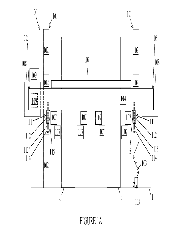
[0018] Referring now to Figure 1A, a schematic side view of an
independent
self-climbing form system 100 to embodiments herein is illustrated. As
CA 03159823 2022-5-27
WO 2021/105771
PCT/1B2020/020070
7
illustrated in Figure 1A, the independent self-climbing form system 100 may
include one or more support towers 101 at a work site 1. The one or more
support towers 101 may be spaced on at the work site 1 to be adjacent to one
or
more vertically rising structures 2. The one or more support towers 101 may be
formed from a plurality of tower segments 102 stacked and coupled on top of
each other. One skilled in the art will appreciate how any number of tower
segments 102 may be used to have the one or more support towers 101 reach a
height for operations on the one or more vertically rising structures 2. In a
non-
limiting example, each tower segment 102 may have a rigid framework made
from a plurality of steel beams, steel columns, pipe sections, square hollow
sections or a combination thereof connected together. Additionally, the
plurality of support towers 102 may have platforms, stairs, ladders or
elevators
103 attached thereto for workers to use. In a non-limiting example, the
platforms, stairs, ladders or elevators 103 may be attached within or outside
the
plurality of support towers 102. It is further envisioned that the platforms,
stairs, ladders or elevators 103 may be independent of the plurality of
support
towers 102 in a free standing structure. For simplicity purposes only, the
platforms, stairs, ladders or elevators 103 are only shown in one tower
segment
102 to avoid confusion in the drawings.
10019] In one or more embodiments, the independent self-climbing form
system 100 may include one or more trusses 104 operationally connected to the
one or more support towers 101. The one or more trusses 104 may extend from
a first end 105 to a second end 106 such that the one or more support towers
101 is connected to the one or more trusses 104 between the first end 105 and
the second end 106. While it is noted that the one or more trusses 104 are
shown as being horizontal trusses, the one or more trusses 104 may be shaped
to have a curve or may be circular without departing from the present scope of
the disclosure. The one or more trusses 104 may have a rigid framework made
from a plurality of steel beams connected together such that walkways and
other surfaces may be formed within and on top of the one or more trusses 104
for workers to use. In a non-limiting example, wood planks or plywood or
CA 03159823 2022-5-27
WO 2021/105771
PCT/1B2020/020070
8
composite boards or metal grate flooring may be placed on the plurality of
steel
beams to form the walkways and surfaces.
10020] In some embodiments, a plurality of platforms (107, 207a, 2076,
207c)
may be operationally connected to the one or more trusses 104. In a non-
limiting example, the plurality of platforms (107, 207a, 207b, 207c) may
include upper platforms 107 and lower platforms (207a, 2076, 207c). Both the
upper platforms 107 and the lower platforms (207a, 207b, 207c) may be
adjustable in real-time to slide toward and away from the one or more
vertically rising structures 2 to accommodate shape and design changes in the
one or more vertically rising structures 2. The upper platforms 107 may be
formed by various platforms (see 107a, 107b, 107c in Figure 1B) on a top
surface of the one or more trusses 104. Additionally, the lower platforms
(207a,
207b, 207c) may be connected on a bottom surface of the one or more trusses
104. In a non-limiting example, a middle lower platform 207a may be provided
to access surfaces of the one or more vertically rising structures 2 below the
one or more trusses 104. Further, an outer surface of the one or more
vertically
rising structures 2 below the one or more trusses 104 may be accessed by a two
tier lower platform having a first lower platform 2076 on top of a second
lower
platform 207c. The first lower platform 2076, in some configurations, may be
offset from the second lower platform 207c to allow for angled movement
along the one or more vertically rising structures 2. The plurality of
platforms
(107, 207a, 2076, 207c) may each be work platforms for workers to work on
the one or more vertically rising structures 2. The plurality of platforms
(107,
207a, 2076, 207c) may retract or extend with respect to the one or more
vertically rising structures 2 to allow for various shapes of the one or more
vertically rising structures 2 to be accommodated within the independent self-
climbing form system 100. It is further envisioned that any of the plurality
of
platforms 107 may be a multi-level deck platform such that platforms may be
on top and below the one or more trusses 104. In a non-limiting example, wood
planks or plywood or composite boards or metal grate flooring may be placed
CA 03159823 2022-5-27
WO 2021/105771
PCT/1B2020/020070
9
on the plurality of platforms (107, 207a, 207b, 207e) to form a path for
workers
to use.
10021]
Additionally, one or more end trusses
108 may be connected at the first
end 105 and the second end 106 of the one or more trusses 104. One skilled in
the art will appreciate how the one or more end trusses 108 may be used to add
weight to the first end 105 and the second end 106 of the one or more trusses
104 to eliminate a sagging in the one or more trusses 104. Additionally, one
or
more housings 109 may be disposed on and/or within the one or more end
trusses 108 and/or the one or more trusses 104. The one or more housings 109
may be a control room, break mom, living corridors, restrooms, and office
buildings. The control room may include controls and a computer system to
manually and/or automatically operate the independent self-climbing form
system 100.
10022]
Still referring to Figure 1A, in one
or more embodiments, screw jacks
111 or hydraulic jacks may be disposed at each connection point of the one or
more trusses 104 on the one or more support towers 101. The screw jacks 111
may be used to vertically move the one or more trusses 104 up and down the
one or more support towers 101. While ills noted that only one screw jack 111
is shown on each support tower 101, this is merely for example purposes only
and a plurality of screw jacks may be used at each support tower 101. The
screw jacks 111, including a motor and gearbox 112, may be coupled to a
threaded rod 113. The threaded rod 113 may extend a length along an outer
surface of the screw jack 111 such that the screw jack 111 climbs up and down
the threaded rod 113. It is further envisioned that an anti-rotational device
114
may be disposed on the threaded rod 113 to ensure that the threaded rod 113
does not rotate. In a non-limiting example, the anti-rotational device 114 may
be a bolt or nut. Further, a locking device 115 may be used to lock the one or
more trusses 104 at a vertical position on the one or more support towers 101.
In a non-limiting example, the locking device 115 may be an arm extending
CA 03159823 2022-5-27
WO 2021/105771
PCT/1B2020/020070
from the threaded rod 113, where the arm may be removably bolted to the
support tower 101.
10023] Referring now to Figure 1B, a schematic top view of the
independent
self-climbing form system 100 to embodiments herein is illustrated. As shown
in Figure 1B, four support towers 101a, 101b, 101c, 101d may be spaced
around the vertically rising structures 2 to space apart a first truss 104a
and a
second truss 104b. Additionally, a first end truss 105a and a second end truss
105b may extend between the first truss 104a and the second truss 104b. In one
or more embodiments, an inner peripheral edge of the first truss 104a, the
second truss 104b, the first end truss 105a, and the second end truss 105b may
delimit a perimeter 116 around the vertically rising structures 2. It is
further
envisioned that a middle truss 110 may be connected from the first truss 104a
to the second truss 104b between the vertically rising structures 2 to split
the
perimeter 116 in two and to provide additional workspace between the
vertically rising structures 2.
100241 In one or more embodiments, upper platforms (107, Figure 1A),
disposed on the first truss 104a and the second truss 104b, may include
various
movable platforms around each vertically rising structures 2. In a non-
limiting
example, the upper platforms (107) may have two end platforms 107a, two side
platforms 107b, and two middle platforms 107c. Additionally, each of the
platforms (107a, 107b, 107c) may extend and retract in a direction shown by
arrows in Figure 1B. In a non-limiting example, each of the platforms (107a,
107b, 107c) may individually move with respect to each other. By individually
moving each of the platforms (107a, 107b, 107c), the independent self-
climbing form system 100 may accommodate essentially any shape or size
change in the vertically rising structures 2.
10025] Now referring to Figures 2A-2I, Figures 2A-2I illustrate various
perspective views of the independent self-climbing form system 100 being
installed, assembled, and operated according to one or more embodiments of
the present disclosure. As shown in Figure 2A, the plurality of support towers
CA 03159823 2022-5-27
WO 2021/105771
PCT/1B2020/020070
11
101a, 101b, 101c, 101d may be erected at the work site 1 to surround the
vertically rising structures 2. While it is noted that four support towers are
shown in Figure 2A, this is merely for example purposes only and any number
of support towers may be used without departing from the scope of the present
disclosure. In a non-limiting example, a crane 200 may lift the rigid
framework
of the plurality of support towers 101a, 101b, 101c, 101d to be upright at the
work site 1. Additionally, each of the plurality of support towers 101a, 101b,
101c, 101d may have a height H corresponding to an initial height ill of the
vertically rising structures 2. In a non-limiting example, the height H of the
plurality of support towers 101a, 101b, 101c, 101d may be greater than the
initial height iH of the vertically rising structures 2 (for example, the
lower
portions of the rising structures 2 may not require scaffolding or an elevated
work surface, whereas the sections to be built above iH may require such). It
is
further envisioned that the plurality of support towers 101a, 101b, 101c, 101d
may be anchored to a ground of the work site 1.
100261 hi one or more embodiments, once the
plurality of support towers 101a,
101b, 101c, 101d are erected, the first truss 104a and the second truss 104b
are
operationally coupled to the plurality of support towers 101a, 101b, 101c,
101d
as shown in Figure 2B. In a non-limiting example, the first truss 104a may be
operationally coupled to the first support tower 101a and the second support
tower 101b. The second truss 104b may be operationally coupled to the third
support tower 101c and the fourth support tower 101d. In some embodiments, a
crane may lift the first truss 104a and the second truss 104b onto the first
support tower 101a and the second support tower 101b, respectively. It is
further envisioned that the first truss 104a and the second truss 104b may be
directly assembled onto the first support tower 101a and the second support
tower 101b, respectively, on a ground level of the work site 1. Additionally,
the
first truss 104a may be spaced a distance D from the second truss 104b such
that the vertically rising structures 2 are in the space between the first
truss
104a and the second truss 104b.
CA 03159823 2022-5-27
WO 2021/105771
PCT/1B2020/020070
12
10027] As shown in Figure 2C, in one or more embodiments, once the
first truss
104a and the second truss 104b are installed, the first end truss 105a and the
second end truss 105b may be coupled to the ends of the first truss 104a and
the
second truss 104b. In a non-limiting example, the first end truss 105a and the
second end truss 105b may each extend from the first truss 104a to the second
truss 104b at ends opposite from each other. Further, the first end truss 105a
and the second end truss 105b may provide additional workspace, restrooms,
break rooms, storage space, and be used for connectivity of the one or more
platforms (see 107 in Figures 1A and 1B). It is further envisioned that the
first
end truss 105a and the second end truss 105b may be replaced with counter-
weight measures at each end of the first truss 104a to the second truss 104b.
In
a non-limiting example, steel or concrete blocks may be provided in each end
of the first truss 104a to the second truss 104b to prevent sagging.
[0028] Additionally, the independent self-climbing form system 100
forms a
work perimeter (116) around the vertically rising structures 2. The work
perimeter (116) may be delimited by the first truss 104a, the second truss
104b,
the first end truss 105a, and the second end truss 105b. Further, the first
truss
104a and the second truss 104b may be positioned and locked on the plurality
of support towers 101a, 101b, 101c, 101d at a vertical positon that may have a
height H' less than the height H of the plurality of support towers 101a,
101b,
101c, 101d.
[0029] Now referring to Figure 2D, in one or more embodiments, the
middle
truss 110 may be connected to and extend from the first truss 104a to the
second truss 104b. Additionally, the middle truss 110 may split the work
perimeter (116) to have one vertically rising structure 2 on adjacent sides of
the
middle truss 110. With the trusses (104a, 10413, 104c, 104d, 105aõ 105b, 110)
installed and assembled, the one or more platforms 107 (see 107a, 107b, 107e,
207a, 207b, 207c described in Figures 1A and 1B) may be operationally
connected to the first truss 104a and the second truss 104b.
CA 03159823 2022-5-27
WO 2021/105771
PCT/1B2020/020070
13
100301 Referring now to Figures 2E-2G, in one or more embodiments, one
or
more formwork panels 202 may be landed on the vertically rising structures 2
and operationally coupled to the one or more platforms 107. The one or more
formwork panels 202 may be used to form an outer surface of the vertically
rising structures 2. In a non-limiting example, the one or more formwork
panels
202 may be rigid such that a shape of the one or more formwork panels 202 is
maintained to allow the outer surface of the vertically rising structures 2 to
be
formed. Additionally, the one or more formwork panels 202 may enclose the
vertically rising structures 2 to form an inner chamber 203 and allow for a
settling of materials of the vertically rising structures 2 such as concrete
that
have been poured.
[0031] In some embodiments, an internal formwork frame 204 may be
inserted
into the inner chamber 203 formed from the one or more formwork panels 202.
In addition, the internal formwork frame 204 may be independent of the one or
more formwork panels 202 such that the internal formwork frame 204 may be
installed before landing the one or more formwork panels 202. In a non-
limiting example, the internal formwork frame 204 may be a steel frame.
Additionally, the internal formwork frame 204 may be used to support an inner
housing of the vertically rising structures 2. With the internal formwork
frame
204, materials such as concrete or composite may be pouted into or onto the
vertically rising structures 2. It is further envisioned that materials such
as
concrete or composite may be poured into or onto the vertically rising
structures 2 without using the internal formwork frame 204.
[0032] Now referring to Figures 2H and 21, in one or more embodiments,
the
vertically rising structures 2 may be further built to have a new height nH
greater than the initial Height ill. With the new height nil of the vertically
rising structures 2, the first truss 104a and the second truss 104b may be
raised
to higher vertical position on the plurality of support towers 101a, 101b,
101c,
101d at a height H". The height H" may be greater than the previous height
(See H' in Figure 2C) of the first truss 104a and the second truss 104b. As
CA 03159823 2022-5-27
WO 2021/105771
PCT/1B2020/020070
14
shown in Figure 2H, the vertically rising structures 2 may be built such that
they are inclined toward each other. As may be readily envisioned based on
Figures 1A, 1B, and 2D-21, the work platforms (see 107 107a, 107b, 107c,
207a, 2071, 207c) may each be adjusted before or during vertical movement of
the first truss 104a and the second truss 104b so as to not damage the
vertically
rising structures 2. Additionally, the work platforms (see 107 107a, 107b,
107c,
207a, 207b, 207c) may be set once the first truss 104a and the second truss
104b reach the new height so as to provide the appropriate work surfaces to
access and continue building the vertically rising structures 2.
10033] As shown in Figure 21, a height of the plurality of support
towers 101a,
101b, 101c, 101d may be increased. In a non-limiting example, each of the
plurality of support towers 101a, 101b, 101c, 101d may have a second tower
segment 102b stacked on top of a first tower segment 102a. A rigid framework
of the second tower segment 102b may couple to a rigid framework of the first
tower segment 102a. Additionally, the first tower segment 102a and the second
tower segment 102b may be bolted together to be locked in place. Further, the
first tower segment 102a and the second tower segment 102b may be
interchangeable such that either tower segment 102a, 102b may be on the
bottom or top and have additional tower segments added thereon. It is further
envisioned that alignment features may be provided on both the first tower
segment 102a and the second tower segment 102b to ensure coupling
connection between each other.
100341 Turning to Figure 3, a flowchart in accordance with one or more
embodiments is shown. Specifically, Figure 3 describes a general method for
using the independent self-climbing form system 100 as described in Figures
1A-2I. One or more blocks in Figure 3 may be performed by a computer
system as described in Figures 4A and 4B. For example, the computer system
may include a non-transitory computer-readable medium with instructions
executable by a processor. The instructions may include functionality to
control
the independent self-climbing form system. While the various blocks in Figure
CA 03159823 2022-5-27
WO 2021/105771
PCT/1B2020/020070
3 are presented and described sequentially, one of ordinary skill in the art
will
appreciate that some or all of the blocks may be executed in different orders,
may be combined or omitted, and some or all of the blocks may be executed in
parallel. Furthermore, the blocks may be performed actively or passively.
[0035] In Block 300, after the independent self-climbing form system
has been
assembled, trusses may vertically move up or down a plurality of support
towers in accordance with one or more embodiments. For example, screw jacks
at each connection point between the at least two trusses and the plurality of
support towers may vertically move the trusses. The screw jacks may be
operated by having each motor and gearbox move the screw jacks up or down a
threaded rod. Additionally, in order to keep the threaded rod from rotating,
an
anti-rotation device (e.g., bolt or nut) may be disposed at an end of the
threaded
rod. It is further envisioned that one or more sensors may be disposed on or
provided within the screw jacks and/or trusses to determine a rate at which
the
trusses are moving.
[0036] In Block 310, once the trusses reach a vertical position for
performing
operation on the vertical structures, each truss may be leveled to be at a
same
height in accordance with one or more embodiments. For example, the screw
jacks may raise the trusses at a rate such that each truss is horizontal and
even
for workers to use and meet safety regulations. It is further envisioned that
one
or more sensors may be used to provide measurements to ensure that the
trusses are level. Likewise, during the vertical moving of the trusses, the
one or
more sensors may provide real-time data to a rate of the vertical movement of
each truss.
[0037] In Block 320, with the trusses level and at the vertical
position for
performing operation on the vertical structures, the trusses may be locked at
the
vertical position on the plurality of support towers with a locking device.
For
example, the locking device may be an arm extending from an end of each
threaded rod of the screw jacks and may be removably bolted to a rigid
framework of the plurality of support towers. By locking the trusses, workers
CA 03159823 2022-5-27
WO 2021/105771
PCT/1B2020/020070
16
may safely access the vertical structures. Additionally, the screw jacks may
also be locked. For example, an anti-rotational device may be disposed on the
threaded rod such that the threaded rod does not rotate to ensure the screw
jacks are non-operational while the trusses are locked.
100381 In Block 330, with the trusses locked, platforms operationally
connected
to the trusses may be extended or retracted in accordance with one or more
embodiments. For example, the platforms surround the vertical structures to
allow for workers to access the vertical structures. The platforms may be
extended to be adjacent and/or rest against the vertical structures.
Additionally,
the platforms may be retracted to create space for the vertical structures and
allow movement of the trusses without damaging the vertical structures and the
components of the independent self-climbing form system.
10039] In Block 340, a determination is made whether the trusses need
to be
raised or lowered in accordance with one or more embodiments. For example,
the vertical structure may be built or repaired in sections based on a
required
height needed such that the trusses are at the vertical positon on the
plurality of
support towers to build or repair the vertical structure. If the answer to the
vertical structure needing being raised or lowered is yes (e.g., building or
repairing the vertical structure at other vertical positions), the flowchart
will
proceed to Block 350. In Block 350, the trusses may be unlocked (e.g.,
unbolting the arm) and will go back to the Block 300 to repeat the previously
mentioned Blocks (300-340). In some embodiments, a position of the trusses
may be adjusted in Block 355 prior to returning to the Block 300 from the
Block 350. For example, the trusses alignment with respect to the plurality of
support towers may be adjusted or leveled such that the trusses are ready to
be
vertically moved.
10040] However, if the answer to whether the trusses need to be raised
or
lowered is no, the flowchart will proceed to Block 360. In Block 360, the
vertical position of trusses may be maintained in accordance with one or more
embodiments. For example, the vertical position is maintained to allow workers
CA 03159823 2022-5-27
WO 2021/105771
PCT/1B2020/020070
17
to perform operations on the vertical structures. It is further envisioned
that the
independent self-climbing form system may also be prepared for disassembly
in Block 360.
10041] In one or more embodiments, the flowchart of Figure 3 allows for
a
worker to manual operate controls of the independent self-climbing form
system or the computer system may automatically operate the independent self-
climbing form system. With the trusses operationally connected to the
plurality
of support towers, any height of the vertical structures may be accessible.
For
example, the independent self-climbing form system may help workers repair
or build the vertical structures without having to anchor into the vertical
structures. One skilled in the art will appreciate how utilizing the
independent
self-climbing form systems disclosed herein allow for fast and quick access to
vertical structures of all shapes and sizes.
10042] With respect to the embodiments discussed above in the Figures
illustrating various views of the independent self-climbing form system (100),
various procedures may be automated to provide faster delivery time in
comparison to manual methods for preparing and transmitting building
operations. For example, a movement of the trusses may be programmed to
automatically occur based on a height of the vertical structure. Moreover, the
platforms extending or retracting may be programmed to automatically occur
based on a shape and size of the vertical structure or based on a movement of
the trusses, for example.
10043] Implementations herein for operating the independent self-
climbing
form system (100) may be implemented on a computing system coupled to a
controller. Any combination of mobile, desktop, server, router, switch,
embedded device, or other types of hardware may be used with the emulsion
generating system (100, 200, 300). For example, as shown in Figure 4, the
computing system 400 may include one or more computer processors 402, non-
persistent storage 404 (e.g., volatile memory, such as random access memory
(RAM), cache memory), persistent storage 406 (e.g., a hard disk, an optical
CA 03159823 2022-5-27
WO 2021/105771
PCT/1B2020/020070
18
drive such as a compact disk (CD) drive or digital versatile disk (DVD) drive,
a
flash memory, etc.), a communication interface 412 (e.g., Bluetooth interface,
infrared interface, network interface, optical interface, etc.), and numerous
other elements and functionalities. It is further envisioned that software
instructions in a form of computer readable program code to perform
embodiments of the disclosure may be stored, in whole or in part, temporarily
or permanently, on a non-transitory computer readable medium such as a CD,
DVD, storage device, a diskette, a tape, flash memory, physical memory, or
any other computer readable storage medium. For example, the software
instructions may correspond to computer readable program code that, when
executed by a processor(s), is configured to perform one or more embodiments
of the disclosure.
10944] The computing system 400 may also include one or more input
devices
410, such as a touchscreen, keyboard, mouse, microphone, touchpad, electronic
pen, or any other type of input device. Additionally, the computing system 400
may include one or more output devices 408, such as a screen (e.g., a liquid
crystal display (LCD), a plasma display, touchscreen, cathode ray tube (CRT)
monitor, projector, or other display device), a printer, external storage, or
any
other output device. One or more of the output devices may be the same or
different from the input device(s). The input and output device(s) may be
locally or remotely connected to the computer processor(s) 402, non-persistent
storage 404, and persistent storage 406. Many different types of computing
systems exist, and the aforementioned input and output device(s) may take
other forms.
10045] The computing system 400 of Figure 4 may include functionality
to
present raw and/or processed data, such as results of comparisons and other
processing. For example, presenting data may be accomplished through
various presenting methods. Specifically, data may be presented through a user
interface provided by a computing device. The user interface may include a
GUI that displays information on a display device, such as a computer monitor
CA 03159823 2022-5-27
WO 2021/105771
PCT/1B2020/020070
19
or a touchscreen on a handheld computer device. The GUI may include
various GUI widgets that organize what data is shown as well as how data is
presented to a user. Furthermore, the GUI may present data directly to the
user, e.g., data presented as actual data values through text, or rendered by
the
computing device into a visual representation of the data, such as through
visualizing a data model. For example, a GUI may first obtain a notification
from a software application requesting that a particular data object be
presented
within the GUI. Next, the GUI may determine a data object type associated
with the particular data object, e.g., by obtaining data from a data attribute
within the data object that identifies the data object type. Then, the GUI may
determine any rules designated for displaying that data object type, e.g.,
rules
specified by a software framework for a data object class or according to any
local parameters defined by the GUI for presenting that data object type.
Finally, the GUI may obtain data values from the particular data object and
render a visual representation of the data values within a display device
according to the designated rules for that data object type.
10046] Data may also be presented through various audio methods. In
particular, data may be rendered into an audio format and presented as sound
through one or more speakers operably connected to a computing device. Data
may also be presented to a user through haptic methods. For example, haptic
methods may include vibrations or other physical signals generated by the
computing system. For example, data may be presented to a user using a
vibration generated by a handheld computer device with a predefined duration
and intensity of the vibration to communicate the data.
10047] As described above, embodiments herein are directed toward an
independent self-climbing form system that may be used to erect, build,
repair,
or otherwise work on a structure. The independent self-climbing form system
may be used in a manner that minimizes or eliminates the need to anchor to or
otherwise interact with the structure, other than to perform the desired work.
Additionally, the moving internal platforms provided at one or multiple levels
CA 03159823 2022-5-27
WO 2021/105771
PCT/1B2020/020070
may allow for unique shaped structures to be accommodated. Further, the
independent self-climbing form system may be altered in height in real time
corresponding to a height of the structure being worked such that the height
of
the independent self-climbing form system is not fixed. Furthermore, the
independent self-climbing form system may include housing for workers to
remain on site during down time to allow for easy and quick startup.
10048] While the invention has been described with respect to a limited
number
of embodiments, those skilled in the art, having benefit of this disclosure,
will
appreciate that other embodiments can be devised which do not depart from the
scope of the invention as disclosed herein. Accordingly, the scope of the
invention should be limited only by the attached claims.
CA 03159823 2022-5-27