Note: Descriptions are shown in the official language in which they were submitted.
Oral Irrigator with Magnetic Attachment
TECHNICAL FIELD
[0002] The present disclosure relates generally to health and personal
hygiene equipment
and more particularly, to oral irrigators.
BACKGROUND
[0003] Oral irrigators typically are used to clean a user's teeth and gums
by discharging a
pressurized fluid stream into a user's oral cavity. The fluid impacts the
teeth and gums to
remove debris. Countertop oral irrigator units include a large reservoir that
connects to a base
unit housing a pump and other internal components. The reservoir on these
types of units may
be wide and cumbersome for a user to remove to refill, such that both a user's
hands might be
needed to manipulate the reservoir. In addition, these units may have multiple
adjustment
levers and knobs, which may contribute to a larger footprint. In some cases,
the fluid tube
coupling the base unit to the oral irrigator handle may become inadvertently
tangled and have a
look that is unorganized and unpleasing to a user when the irrigator handle is
stored. The fluid
tube may also interfere with the storage of the oral irrigator.
[0004] The information included in this Background section of the
specification, including
any references cited herein and any description or discussion thereof, is
included for technical
reference purposes only and is not to be regarded subject matter by which the
scope of the
disclosure is to be bound.
1
Date Recue/Date Received 2022-05-24
SUMMARY
[0005] The present disclosure provides an oral irrigator with magnetic
attachment, as
described below and defined in the accompanying claims. In one embodiment, an
oral irrigator
assembly may include a base including a pressure assembly, a pump assembly, a
motor
assembly, and a cradle. The pressure assembly may include a control valve and
may be fluidly
connected to the pump assembly. The motor assembly may be electrically
connected to the
pump assembly. The oral irrigator assembly may include a reservoir with a lid
adjustably
coupled to the reservoir, the reservoir positioned adjacent to the base and
fluidly coupled to the
pressure assembly. The oral irrigator assembly may include a control assembly
with a push
button at least partially surrounded by a rotating or sliding knob. The push
button may be
configured to engage a power button to electrically connect the motor assembly
to the pump
assembly. The knob may be coupled to the control valve. The oral irrigator
assembly may
include an oral irrigator handle fluidly coupled to the pump assembly, the
pressure assembly,
and the reservoir. The oral irrigator handle may be adjustably coupled to the
base at the cradle.
[0006] Another embodiment of the present disclosure includes an oral
irrigator assembly.
The oral irrigator assembly may include a base unit and an oral irrigator
handle. The base unit
may include a first positioning feature. The oral irrigator handle may include
a second
positioning feature. The second positioning feature of the oral irrigator
handle may correspond
with the first positioning feature of the base unit to removably couple the
oral irrigator handle to
the base unit. The oral irrigator handle may be removably coupled to the base
unit at any one
of a plurality of desired positions relative to the base unit.
[0007] Another embodiment of the present disclosure includes a control
assembly for an
oral irrigator assembly. The control assembly may include a first element
arranged to
selectively alter a first operating state of the oral irrigator assembly. The
control assembly may
include a second element arranged to rotate at least partially about the first
element to
selectively alter a second operating state of the oral irrigator assembly.
[0008] Another embodiment of the present disclosure includes an oral
irrigator assembly.
The oral irrigator assembly may include a base including a pressure assembly,
a fluid reservoir
removably coupled to the base, an oral irrigator handle fluidly coupled to the
fluid reservoir and
the pressure assembly, and a control assembly including a push button at least
partially
surrounded by a knob. The oral irrigator handle may be adjustably coupled to
the base via a
magnetic attachment. The push button may be arranged to engage a power button
to turn the
oral irrigator assembly on and off. The knob may be coupled to the pressure
assembly to adjust
2
Date Recue/Date Received 2022-05-24
at least one of a pressure and a volume of a fluid expelled through the oral
irrigator handle upon
movement of the knob.
[0009] This Summary is provided to introduce a selection of concepts in a
simplified form
that are further described below in the Detailed Description. This Summary is
not intended to
identify key features or essential features of the claimed subject matter, nor
is it intended to be
used to limit the scope of the claimed subject matter. A more extensive
presentation of features,
details, utilities, and advantages of the present disclosure as defined in the
claims is provided in
the following written description of various embodiments of the disclosure and
illustrated in the
accompanying drawings.
BRIEF DESCRIPTION OF THE DRAWINGS
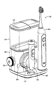
[0010] Fig. 1 is an isometric view of an embodiment of an oral irrigator
assembly.
[0011] Fig. 2 is an isometric view of a base unit and a reservoir of the
oral irrigator
assembly of Fig. 1.
[0012] Fig. 3A is an isometric view of the reservoir with a lid in a first
open position.
[0013] Fig. 3B is an isometric view of the reservoir with the lid in a
second open position.
[0014] Fig. 3C is a cross-sectional view of the lid taken along line 3C-3C
of Fig. 2.
[0015] Fig. 3D is a cross-sectional view of the lid taken along line 3D-3D
of Fig. 2.
[0016] Fig. 4 is an isometric view of the base unit.
[0017] Fig. 5 is a front isometric view of a protrusion or tube nest.
[0018] Fig. 6 is a rear isometric view of the tube nest of Fig. 5.
[0019] Fig. 7 is a fragmentary cross-sectional view of an oral irrigator
handle coupled to
the tube nest and taken along line 7-7 of Fig. 1.
[0020] Fig. 8A is an exploded front isometric view of a control assembly.
[0021] Fig. 8B is an exploded rear isometric view of the control assembly
of Fig. 8A.
[0022] Fig. 9 is a rear isometric view of a push button of the control
assembly.
[0023] Fig. 10A is a rear isometric view of a rotating knob of the control
assembly.
[0024] Fig. 10B is a cross-sectional view of the rotating knob taken along
line 10B-10B of
Fig. 10A.
[0025] Fig. 11A is a front isometric view of a bezel of the control
assembly.
[0026] Fig. 11B is a rear isometric view of the bezel of Fig. 11A.
[0027] Fig. 11C is a cross-sectional view of the bezel taken along line
11C-110 of Fig.
11A.
3
Date Recue/Date Received 2022-05-24
[0028] Fig. 12 is a fragmentary, cross-sectional view of the base unit
taken along line 12-
12 of Fig. 4.
[0029] Fig. 13 is an isometric view of a pump assembly and a pressure
assembly and a
partial view of a motor assembly.
[0030] Fig. 14 is a fragmentary, cross-sectional view of the control
assembly, the pressure
assembly, and the motor assembly taken along line 14-14 of Fig. 4.
[0031] Fig. 15 is a fragmentary, cross-sectional view of the control
assembly, the pressure
assembly, and the pump assembly taken along line 15-15 of Fig. 4.
[0032] Fig. 16 is an isometric view of another embodiment of an oral
irrigator assembly.
DETAILED DESCRIPTION
[0033] In some examples, an oral irrigator assembly may include a control
assembly
having first and second elements operable to alter first and second operating
states of the oral
irrigator assembly. The first and second elements may be positioned for
compact operation.
For example, the second element may be arranged to rotate at least partially
about the first
element to reduce the overall size of the control assembly compared to some
traditional
designs. The first element may control a first function of the oral irrigator
assembly. The
second element may control a second function of the oral irrigator assembly.
The first element
may be a push button. The second element may be a rotating or sliding knob.
The push button
may be selectively depressed to turn the oral irrigator assembly on and off.
The oral irrigator
assembly may include a control valve coupled to the knob. Selective movement
of the knob
may vary the volume and/or pressure of a fluid expelled through an oral
irrigator handle. The
first and second elements may move in first and second directions. For
instance, the first
element may move axially along an axis about which the second element at least
partially
rotates. Alternatively, the first and second elements may move axially along
generally
orthogonal directions.
[0034] In some examples, the oral irrigator handle may include a homing
feature that
assists a user in positioning the oral irrigator handle adjacent to a base
unit. In one example,
the homing feature of the oral irrigator handle may assist a user in
positioning the handle within
or adjacent a cradle extending from the base unit. The cradle may include a
complementary
homing feature such that the handle easily aligns to a correct position
adjacent to the cradle,
such as cantilevered off an end face of the cradle. In this manner, the homing
features may
make placement of the handle in a correct position easier for the user.
4
Date Recue/Date Received 2022-05-24
[0035] In addition to facilitating easy placement of the handle in a
correct position, the
homing feature(s) may also allow the base unit to include a slimmer profile
compared to some
traditional designs. For instance, some traditional designs include a C-clamp
type structure to
hold an oral irrigator handle. The homing feature(s) of the present
disclosure, however, allow
the traditional C-clamp holding structure to be removed from the base unit,
thereby allowing the
base unit to have a more compact shape. The homing feature(s) may also allow
greater
freedom in designing the oral irrigator handle. For example, without the need
of designing the
handle to fit within a C-clamp type structure, the handle may be designed with
shapes that are
more aesthetically appealing and/or more comfortable to, and/or easier to
manipulate by, a user
compared to traditional designs. In particular, the handle may be more uniform
in cross-section
with less taper along its length compared to traditional designs.
[0036] The homing features may be any suitable mechanism or assembly
operable to
quickly and easily couple the oral irrigator handle to the base unit. For
example, the homing
features may include complimentary magnetic materials or devices to
magnetically couple the
oral irrigator handle to the base unit in one or more relative positions. The
magnetic materials
or devices may be positioned such that magnetic attachment of the oral
irrigator handle to the
base unit automatically aligns the oral irrigator handle relative to the base
unit. For instance, the
magnetic coupling of the oral irrigator handle to the base unit may vertically
align the oral
irrigator handle along the base unit. Additionally or alternatively, the
magnetic coupling of the
oral irrigator handle to the base unit may position the oral irrigator handle
at one or more
predetermined or desired vertical positions relative to the base unit. For
instance, the magnetic
coupling of the oral irrigator handle to the base unit may position the oral
irrigator handle in one
of a plurality of set positions along the base unit. Alternatively, the
magnetic coupling of the oral
irrigator handle to the base unit may position the oral irrigator handle at
any desired position
along the base unit based on user preference. In such examples, the
positioning of the oral
irrigator handle may be restrained only by the size of the homing features
themselves. For
example, the homing features may define minimum and maximum spacing relative
to the base
unit, with the oral irrigator handle able to be positioned at any location
within the minimum and
maximum positions.
[0037] Fig. 1 is an isometric view of an oral irrigator assembly 100. Fig.
1 shows the oral
irrigator assembly 100 with a base 102 and a reservoir 114 coupled to the base
102. The
reservoir 114, which may be referred to as a fluid reservoir, may be removably
or fixedly
coupled to the base 102. The reservoir 114 may be coupled to the base 102 in
many
configurations. For example, the reservoir 114 may be positioned at least
partially on top of the
Date Recue/Date Received 2022-05-24
base 102. As shown in Fig. 1, a toothbrush 104 and an oral irrigator handle
106 may be
releasably coupled to the base 102. For instance, at least one of the
toothbrush 104 and the
oral irrigator handle 106 may rest on the base 102, may be secured to a
vertical face or wall of
the base 102, or the like, or any combination thereof. The oral irrigator
handle 106 may be
coupled to a tube 108 that is stored around a tube nest 110. The tube nest 110
may be coupled
to the base 102. The base 102, which may be referred to as a base unit, may
also have a
control assembly 112. The reservoir 114 may have a lid 116. In some examples,
the
toothbrush 104 is removable from the base 1 02. The oral irrigator handle 106
may be
removably coupled to the base 102 at the tube nest 110, and fluidly connected
to the reservoir
114 through the tube 108. The oral irrigator handle 106 may be connected to a
jet tip 107
(shown in Fig. 16). As explained below, the oral irrigator handle 106 may be
adjustably coupled
the base 102.
[0038] Fig. 2 is an isometric view of the oral irrigator assembly 100 of
Fig. 1, with the
toothbrush 104, oral irrigator handle 106, and tube 108 removed for
illustration purposes. As
shown in Fig. 2, the tube nest 110 may include a cradle 118 configured to hold
the oral irrigator
handle 1 06. In some examples, the cradle 118 may include a shape
complementary to that of
the oral irrigator handle 106 for complementary engagement therewith. For
instance, the cradle
118 may be curved to complement or generally complement an outer profile shape
of the oral
irrigator handle 106. In some examples, the base 102 may have a tube routing
aperture 122
formed in an extension 103 of the base 102. The extension 103 may be generally
rectangular
shaped and may horizontally extend away from a lower portion of the main body
of the base
102. In such examples, the extension 1 03 may define a shelf on which the
toothbrush 104
and/or oral irrigator handle 106 may be stored.
[0039] Fig. 16 is an isometric view of another embodiment of an oral
irrigator assembly
1600. Unless otherwise noted, the oral irrigator assembly 1600 of Fig. 16 is
configured similarly
to the oral irrigator assembly 100 described herein. For instance, with
reference to Fig. 16, the
oral irrigator assembly 1600 may differ from the oral irrigator assembly 100
of Figs. 1 and 2 in
that the oral irrigator assembly 1600 of Fig. 1 6 does not include toothbrush
104. In all or
substantially all other aspects, however, the oral irrigator assembly 1600 may
be similar to oral
irrigator assembly 100.
[0040] Figs. 3A and 3B show a reservoir assembly 126 with the lid 116 in
different open
positions. Fig. 3A is an isometric view of the reservoir 114 with the lid 116
in a first open
position. Fig. 3B is an isometric view of the reservoir 114 with a lid 116 in
a second open
position. Figs. 30 and 3D are cross-sectional views of a hinge structure of
the lid 116.
6
Date Recue/Date Received 2022-05-24
Referring to Figs. 3A-3D, the lid 116 may have an adjustable portion 128 that
may rotate with
respect to a fixed portion 130 about hinges 134 that pivotally couple the
adjustable portion 128
and the fixed portion 130 together. Both the adjustable portion 128 and the
fixed portion 130
may have vents 132. In some examples, the fixed portion 130 may be adjustably
secured to the
reservoir 114, while the adjustable portion 128 may couple with the reservoir
114 when the
adjustable portion 128 is in a closed position, as shown in Figs. 1 and 2.
[0041] Referring to Figs. 3C and 3D, the hinges 134 may be defined as
first and second
links 127, 129 connected together. Depending on the particular application,
the first and second
links 127, 129 may be formed integrally as a single element, or may be
separate elements
connected together, either fixedly or otherwise. The first link 127 may be
attached to the
adjustable portion 128 of the lid 116. As shown in Figs. 3C and 3D, the second
link 129 may
extend from a distal end 131 of the first link 127. The second link 129 may
extend at an angle
to the first link 127. The angle between the first and second links 127, 129
may be an acute
angle, a 90 angle, or an obtuse angle to allow the adjustable portion 128 to
pivot relative to the
fixed portion 130. The angle between the first and second links 127, 129 may
also define a fully
opened position of the adjustable portion 128. For instance, the adjustable
portion 128 may be
moved away from the reservoir 114 until the second link 129 of the hinge 134
contacts a portion
of the fixed portion 130 to define a fully opened position of the lid 116. In
such examples, a
larger angle between the first and second links 127, 129 may allow the
adjustable portion 128 to
move further away from the reservoir 114. In like manner, a smaller angle
between the first and
second links 127, 129 may limit the amount of rotation of the adjustable
portion 128 away from
the reservoir 114.
[0042] With continued reference to Figs. 3C and 3D, a pivot assembly 133
may be coupled
to the fixed portion 130 to which the second link 129 is rotatably coupled.
For example, a distal
end 135 of the second link 129 may define a clip structure 141 sized and
shaped to surround a
majority of a pivot shaft 143 of the pivot assembly 133. In one example, the
clip structure 141
may include opposing sections or fingers 145 defining a crescent shape to at
least partially
surround the pivot shaft 143, though other suitable configurations are
contemplated. The hinge
134 may rotate about the pivot shaft 143 to move the adjustable portion 128
between open and
closed positions.
[0043] In some examples, the lid 116 may include structure operable
releasably hold the
adjustable portion 128 in an open position. For example, as shown in Fig. 3D,
a tab 146 may
extend from the first link 127 and/or the second link 129 of the hinge 134. A
distal end 148 of
the tab 146 may be curved or angled to define a seat 150. With continued
reference to Fig. 3D,
7
Date Recue/Date Received 2022-05-24
a post 152 may extend from the fixed portion 130. As the adjustable portion
128 moves relative
to the fixed portion 130, the tab 146 may move relative to the post 152 until
the post 152
engages the seat 150 at which point further movement of the tab 146 relative
to the post 152
may be limited (see Fig. 3B). In this position, the adjustable portion 128 of
the lid 116 may be
releasably held in place to allow easy filling of the reservoir 114.
[0044] The reservoir 114 may be formed with two opposing generally planar
sides 136,
138 that are generally normal to a generally planar front face 140 that
opposes a generally
planar rear face 142. In some examples, the sides 136, 138 have a width that
is smaller than a
width of each of the front face 140 and the rear face 142. A bottom 137 of the
reservoir 114
may be configured with a sealable port 139 to couple to a valve assembly 144
to fluidly connect
the reservoir 114 with a pressure assembly and a pump assembly in the base
102, as described
more fully below.
[0045] Figs. 4-6 show the base 102 and various components of the oral
irrigator assembly
100. Fig. 4 is an isometric view of an oral irrigator base 102. The base 102
may have an outer
housing or shell 200 that houses a portion of the control assembly 112, a
motor assembly 504,
a pressure assembly 502, and a pump assembly 500. The base 102 may have a
charging post
120 configured to provide an electric charge to the toothbrush 104 to maintain
or recharge the
battery power of the toothbrush 104 when it is coupled to the base 102. The
charging post 120
may be formed using a portion of the outer housing 200 covering the extension
103 of the base
102 and various electrical components stored within the outer housing 200.
[0046] Figs. 5 and 6 are front and rear isometric views of the tube nest
110. As shown, a
portion of the tube nest 110 may extend away from a front face 202 of the base
102 to form a
protrusion 222. The protrusion 222 may be generally cylindrically shaped with
a taper from a
larger diameter at its rear 226 located proximal to the front face 220 towards
its front 228. In
some examples, the protrusion 222 and the front face 220 may be separate
components
connected together or they may be molded together as a single piece. The
interface between
the protrusion 222 and the front face 220 may form a tube recess 124. The tube
recess 124
may be formed such that it extends rearward of the front face 220 in a
direction opposite that of
the tube nest 110. The tube recess 124 may have a width that is larger than a
diameter of the
tube 108 shown in Fig. 1. This may allow for the tube 108 to be wrapped about
the protrusion
222 and seat within the tube recess 124.
[0047] The tube nest 110 may also have a channel 230 formed in a lower
portion thereof,
the tube nest 110 extending downward from the tube recess 124. The channel 230
may have a
8
Date Recue/Date Received 2022-05-24
width and depth that is larger than the diameter of the tube 108 shown in Fig.
1, as to allow the
tube 108 to sit within the channel 230.
[0048] A portion of the front 228 of the protrusion 222 may be formed as
the cradle 118.
The cradle 118 may have a concave shape that curves away from the front 228
and towards the
rear 226 of the protrusion 222. In some examples, the cradle 118 may be formed
with
attachment or securing devices to help position or temporarily secure the oral
irrigator handle
106 so that it is adjacent the cradle 118 when stored by a user. In some
examples, the cradle
118 may be formed from a magnetic material to help secure or position the oral
irrigator handle
106. In some examples, the oral irrigator handle 106 has a complementary
attachment,
securing, or homing device to releasably position or secure the oral irrigator
handle 106 at least
partially within or adjacent to the cradle 118.
[0049] With reference to Fig 6, the protrusion 222 may form a hollow
interior cavity 232
defined by an interior face 234 and sidewall 236. In some examples, interior
ribs 238 may
extend from the interior face 234 and sidewall 236 of the protrusion 222. As
shown, the ribs 238
may extend radially inward from the sidewall 236, though other suitable
configurations are
contemplated. In some examples, the base 102 (e.g., the protrusion 222) may
include a first
positioning feature. For example, a magnetic coupling device, such as a first
magnet device
240 or magnetic material, may be positioned within the interior cavity 232 of
the protrusion 222.
For example, the first magnet device 240 may be defined or positioned on the
interior face 234
and/or the ribs 238. In some examples, the first magnet device 240 may be held
in place by the
ribs 238 or positioned between the ribs 238. In some examples, the ribs 238
may also be
formed from a magnetic material. In some cases, a stronger magnetic material
may be coupled
to or positioned adjacent to the interior face 234 while a weaker magnetic
material may be used
to form the ribs 238. This may help the cradle 118 to act as a homing device
for the
complementary attachment or securing device of the oral irrigator handle 106.
[0050] Fig. 7 is a fragmentary cross-sectional view showing the oral
irrigator handle 106
coupled to the protrusion 222. Referring to Fig. 7, the oral irrigator handle
106 may include a
second positioning feature corresponding with the first positioning feature of
the base 102 to
removably couple the oral irrigator handle 106 to the base 102. As explained
below, the first
and second positioning features may allow the oral irrigator handle 106 to be
removably coupled
to the base 102 at any one of a plurality of desired positions relative to the
base 102. As shown
in Fig. 7, the second positioning feature may be a second magnet device 242.
The second
magnet device 242 may be defined or positioned on or within the oral irrigator
handle 106. For
example, at least a portion of the oral irrigator handle 106 may be formed
from a magnetic
9
Date Recue/Date Received 2022-05-24
material to magnetically couple the oral irrigator handle 106 to the cradle
118. In such
examples, the second magnet device 242 of the oral irrigator handle 106 may be
magnetically
attracted to the first magnet device 240 of the base 102 to magnetically
couple the oral irrigator
handle 106 to the base 102. For instance, the magnetic attraction between the
first and second
magnet devices 240, 242 may magnetically couple the oral irrigator handle 106
to the cradle
118 when the oral irrigator handle 106 is positioned near the protrusion 222.
In this manner, the
first and second magnet devices 240, 242 may automatically align the oral
irrigator handle 106
into a correct storage position. In this way, the first and second magnet
devices 240, 242 may
act as homing features that assist a user in positioning the oral irrigator
handle 106 adjacent to
the base 102.
[0051] The first and second magnet devices 240, 242 may be arranged to
removably
couple the oral irrigator handle 106 to the base 102 at any one of a plurality
of desired positions
relative to the base 102. In particular, the first and second magnet device
240, 242 may
removably couple the oral irrigator handle 106 to the base 102 at any one of a
plurality of
vertically adjacent positions relative to the base 102. For instance, the
first and second magnet
devices 240, 242 may be arranged to position the oral irrigator handle 106 at
a desired spacing
above the extension 103 of the base 102. This may allow a user to couple the
oral irrigator
handle 106 to the base 102 at a desired vertical position based on user
preference. For
instance, the protrusion 222 may be coupled to the oral irrigator handle 106
at any position
along the length of the oral irrigator handle 106 to allow user positioning of
the oral irrigator
handle 106 nearer or further away from the extension 103 as desired. In this
manner, a user
may position the oral irrigator handle 106 nearer the extension 103 to reduce
a height of the oral
irrigator assembly 100, which may allow the oral irrigator assembly 100 to be
positioned or
stored in smaller spaces compared to traditional designs, such as underneath a
shelf or within a
cabinet, among others.
[0052] In some examples, the magnetic composition of the interior face 234
and/or the ribs
238 may allow for the oral irrigator handle 106 to be magnetically attracted
to the cradle 118
when the oral irrigator handle 106 is positioned near the cradle 118. For
example, the oral
irrigator handle 106 may include a complimentary or corresponding magnetic
coupling device,
such as a magnet or a magnetic material, that magnetically couples the oral
irrigator handle 106
to the cradle 118. In some examples, the stronger pull of the interior face
234 may assist the
user in properly positioning the oral irrigator handle 106 within or adjacent
to the cradle 118. In
some examples, the complementary attachment or securing devise of the oral
irrigator handle
106 may be positioned so that the oral irrigator handle 106 may always be
stored in a set
Date Recue/Date Received 2022-05-24
position or a plurality of positions. This may allow the user easier access as
the oral irrigator
handle 106 is generally stored in the correct position that allows for the
user to easily grasp the
handle and remove it from the cradle 118.
[0053] Figs. 8A-12 show various views of a user interface or control
assembly 112 and its
components. Figs. 8A and 8B are exploded front and rear isometric views of the
control
assembly 112. Figs. 8A and 8B show a push button 302, a knurled knob 304, a
rotating or
sliding knob 306, a coupling link 308, a bezel 310, a button 312, a switch
314, a control valve
318, and a valve face plate 316. The control valve 318 may be configured
similarly to the valve
structure disclosed in U.S. Patent Application Publication No. 2011/0097683.
The general features of the various
components illustrated in Figs. 8A and 8B will now be described.
[0054] Fig. 9 is a rear isometric view of the push button 302, which may
be referred to as a
power button. Fig. 9 shows the push button 302 with a front face 324 and a
rear face 330
opposing the front face 324. The front face 324 and the rear face 330 may be
generally planar.
The front face 324 and the rear face 330 may be generally circular in shape
and separated by a
perimeter wall 332. The perimeter wall 332 may be generally normal to both the
front face 324
and the rear face 330 and form an outer perimeter or circumference of the push
button 302.
[0055] A first leg 320 and a second leg 322 may extend from the rear face
330 away from
the front face 324 of the push button 302. The first and second legs 320, 322
may each have a
tab 334 on an end thereof that is distal the rear face 330. Each tab 334 may
extend away from
its associated leg 320 or 322. For instance, the tabs 334 may extend in a
direction
perpendicular to the first and second legs 320, 322 and away from a central
axis 380. For
example, depending on the particular application, the tabs 334 may extend away
from each
other, in a direction radially away from the central axis 380, or the like.
The first and second
legs 320, 322 may be shaped similar to, or different from, each other. For
instance, the first leg
320 may be longer than the second leg 322, or vice-versa. Each tab 334 may act
as a detent to
position the push button 302 within the control assembly 112.
[0056] A cylindrically shaped bias element 326 and cylindrically shaped
central core 328
may also extend from the rear face 330 away from the front face 324. The
central core 328 may
have a diameter that is smaller than the diameter of the bias element 326. The
central core 328
may be a hollow cylinder centered about the central axis 380. The central core
328 may have a
first end 344 adjacent the rear face 330, and a second end 346 opposite the
first end 344, and
an outside surface 348 and an inside surface 350. The second end 346 may also
be beveled
on an inner edge.
11
Date Recue/Date Received 2022-05-24
[0057] The bias element 326 may have a diameter that is smaller than a
diameter of the
front face 324 and the rear face 330. The bias element 326 is cylindrically
shaped with an
upper arc portion 335 located above the first and second legs 320, 322 and a
lower arc portion
336 located below the first and second legs 320, 322. The upper arc portion
335 may have a
stabilizer 342 adjacent the rear face 330 and extending away from the front
face 324. The
stabilizer 342 may be formed from a plurality of ribs and protrusions
extending away from the
rear face 330. A connector 340 extends from the stabilizer 342 to connect the
stabilizer 342 to
the middle of a flexible arcuate finger 338. The connector 340 may be single
protrusion or
extrusion. The flexible finger 338 may be a portion of a cylinder with a
resting diameter that is
configured to flex radially outward to a larger diameter when the flexible
finger 338 contacts a
seat of the knob 306, as explained below. The flexible finger 338 may be
formed with two
arcuate band-shaped portions connected to each other at their respective ends.
The lower arc
portion 336 may be similarly shaped and function similarly to the upper arc
portion 335. For
example, the lower arc portion 336 may include a stabilizer 343 connected to a
flexible finger
339 by a connector 341 in a manner similar to that described above. Though the
bias element
326 is shown and described as a molded in biasing structure, in some examples,
the bias
element 326 may be a spring coupled to the push button 302. For instance,
depending on the
particular application, the bias element 326 may be a metal spring extending
around the central
core 328, such as annularly spaced from the central core 328.
[0058] Fig. 10A is a rear isometric view of the knob 306. Fig. 10B is a
cross-sectional view
along line 10B-10B of Fig. 10A. The knob 306 may have an outer ring 360 that
is connected to
a central core 366 by both a web 368 and seat 384. The outer ring 360 may be
cylindrically
shaped about the central axis 380, with an outside perimeter formed by a
knurled knob
mounting surface 362 and an abutting wall 364. The knurled knob mounting
surface 362 may
have a diameter smaller than the diameter of the abutting wall 364. The
knurled knob mounting
surface 362 may have ribs 382 extending therefrom. In one example, the ribs
382 may extend
away from the central axis 380, such as radially away from the central axis
380. The outer ring
360 may have a leading edge 363 at the end of the knurled knob mounting
surface 362 opposite
the end adjacent to the abutting wall 364.
[0059] The outer ring 360 may be connected to the central core 366 through
the web 368
and seat 384. The web 368 and the seat 384 may be somewhat orthogonal to the
outer ring
360. The seat 384 may be shaped as an annular ring, with a proximal mating
face 386 and a
distal mating face 388 opposite the proximal mating face 386. The seat 384 may
be convexly
shaped, and shallowly curve away from the center of the oral irrigator
assembly 100. In some
12
Date Recue/Date Received 2022-05-24
examples, the proximal mating face 386 may form an angle that is less than 90
degrees with the
abutting wall 364. The seat 384 may connect to the abutting wall 364 of the
outer ring 360 at a
step 390. An inner portion of the seat 384 may connect with the web 368.
[0060] In some examples, the web 368 may connect the seat 384 to an outer
surface 376
of the central core 366. In some examples, the web 368 may be a plurality of
spokes, each with
an inner edge 392 adjacent to the central core 366 and an outer edge 394
adjacent to the seat
384. The spokes may taper in width from the seat 384 to the central core 366.
For example,
the inner edge 392 may have a length that is shorter than the length of the
outer edge 394.
Similar to the seat 384, the web 368 may also be convexly shaped, and
shallowly curve away
from the center of the oral irrigator assembly 100. In the example of Fig.
10A, two arcuate
spaces 385 may be formed between the seat 384, the web 368, and the central
core 366.
[0061] The central core 366 may be cylindrically shaped, with the outer
surface 376 and
an interior surface 378. The central core may have a front edge 372 that is
proximal to the
leading edge 363 of the outer ring 360, and a rear edge 374 opposite that of
the front edge 372.
In some examples, an annular seat 398 is formed in the outer surface 376 near
the rear edge
374. The annular seat 398 may be formed as a recessed area that encompasses
the
circumference of the central core 366.
[0062] A plurality of alignment tabs 370 may extend inward from the
interior surface 378
towards the central axis 380. In some examples, the alignment tabs 370 are
spaced apart in
pairs about a circumference of the interior surface 378, such that a spacing
between a first tab
and a second tab is equal to the spacing between a third tab and a fourth tab,
but the spacing
between the first and the third tabs and the second and fourth tabs is larger
than between the
first and second tabs. The paired tabs 370 may be used to align the coupling
link 308 within the
control assembly 112, as further described herein.
[0063] Figs. 11A-11C are various views of the bezel 310. Fig. 11A is a
front isometric view
of the bezel 310, Fig. 11B is a rear isometric view of the bezel 310, and Fig.
11C is a cross-
sectional view along line 11C-11C of Fig. 11A. Referring to Figs. 11A-11C, the
shape of the
bezel 310 may be formed at least partially by two concentric cylinders or
walls. For example, an
outer wall 410 may form a larger, outer cylinder, and two curved support walls
418 and two
connecting nubs 416 may together form a smaller, inner cylinder. A knob mating
wall 408 may
connect the outer wall 410 to the curved support walls 418 and connecting nubs
416. A
perimeter wall 404 extends as a flange about the outer wall 410.
[0064] The outer portion of the bezel 310 may be formed by the perimeter
wall 404. As
shown, the perimeter wall 404 may include a base mating face 400 and a rear
face 402
13
Date Recue/Date Received 2022-05-24
opposite the base mating face 400. The cross-sectional view of Fig. 110 shows
that the
perimeter wall 404 may have a generally concave shape that curves away from
the center of the
oral irrigator assembly 100. The curved shape of the perimeter wall 404 may
mimic the shape
of an internal wall of the base 102 adjacent to which the bezel 310 may be
positioned.
[0065] The outer perimeter of the perimeter wall 404 may be generally
annularly shaped
except near a top portion that increases in diameter to form a tab 405 with an
alignment slot
406. The alignment slot 406 may be formed in the upper portion of the
perimeter wall 404,
proximal to the reservoir 114 of the oral irrigator assembly 100. The
alignment slot 406 may be
used to align the rotational position of the bezel 310 with respect to the
base 102.
[0066] The outer wall 410 may extend orthogonally from the base mating
face 400 of the
perimeter wall 404 and away from the rear face 402. The outer wall 410 may
connect the knob
mating wall 408 to the perimeter wall 404. At the intersection of the outer
wall 410 and the knob
mating wall 408, a lip 420 may be formed.
[0067] The knob mating wall 408 may be generally orthogonal to the outer
wall 410. The
knob mating wall 408 may have a proximal face 412 and a distal face 414. The
knob mating
wall 408 may be annularly shaped, with an outer perimeter formed at the outer
wall 410 and an
inner perimeter formed by the curved support walls 418 and the connecting nubs
416. The
knob mating wall 408 may be curved with an angle that mirrors the angle of the
web 368 and
seat 384 of the knob 306.
[0068] A plurality of leg receiving ports 422 may be formed within the
knob mating wall 408
and include an aperture that extends between the proximal face 412 and the
distal face 414.
The leg receiving ports 422 may also extend orthogonally from the proximal
face 412 and away
from the distal face 414. In some examples, the leg receiving ports 422 may
have a cross-
sectional shape that is generally rectangular, similar to the shape shown in
Fig. 11A. In other
examples, the cross-sectional shape may be round, triangular, oblong or other
similar shapes.
[0069] In some examples, the leg receiving ports 422 may have an inner
edge proximal to
a central bore 424 formed by the curved support walls 418 and connecting nubs
416. The inner
edge of the leg receiving ports 422 may curve outward from the central bore
424, similar to the
shape of the curved support walls 418. In some examples, the leg receiving
ports 422 are
spaced equally about the central bore 424.
[0070] The central bore 424 may be formed through the proximal face 412
and the distal
face 414 of the knob mating wall 408. The curved support walls 418 and
connecting nubs 416
may extend orthogonally from the distal face 414 and away from the proximal
face 412. The
curved support walls 418 may have a generally constant thickness and may be
curved about
14
Date Recue/Date Received 2022-05-24
the central axis 380. The connecting nubs 416 may taper in thickness from a
larger width
adjacent the distal face 414 to a smaller width with distance away from the
distal face 414. At
opposite distal edge of the connecting nubs 416, a detent 426 may be formed.
The detent 426
may be a raised feature that extends inwardly from the connecting nub 416 and
towards the
central axis 380.
[0071] With reference to Fig. 8A and 8B, the coupling link 308 may have a
cylindrical
center portion 309 positioned between two bulbous ends 311. In some examples,
the bulbous
ends 311 may be spherically shaped. Each bulbous end 311 may have two fingers
313 that
protrude from opposite sides. The fingers 313 may be cylindrically shaped to
couple with the
control valve 318 and the knob 306.
[0072] Figs. 13-15 show various views of the control assembly 112, a
pressure assembly
502, a pump assembly 500, and a motor assembly 504. Fig. 13 is an isometric
view of the pump
assembly 500, the pressure assembly 502 and a partial view of the motor
assembly 504. Fig.
14 is a cross-sectional isometric view of the control assembly 112, the
pressure assembly 502,
and the motor assembly 504 along line 14-14 of Fig. 4. Fig. 15 is a cross-
sectional isometric
view of the control assembly 112, pressure assembly 502, the pump assembly
500, and the
motor assembly 504 along line 15-15 of Fig. 4.
[0073] The various components of the pressure assembly 502 will now be
described. As
shown in Fig. 15, the pressure assembly 502 may be fluidly connected to the
reservoir valve
actuator 524. The reservoir valve actuator 524 may be configured to allow
fluid stored within
the reservoir 114 to flow through a channel in the reservoir valve actuator
524 and into a
pressure assembly housing 506 of the pressure assembly 502. The top portion of
the reservoir
valve actuator 524 may have engagement points that contact the valve assembly
144, and help
compress a spring in the valve assembly 144. The compression of the spring
with the valve
assembly 144 allows the valve assembly 144 to disengage from the sealable port
139. Once
the valve assembly 144 is disengaged from the sealable port 139, fluid may
flow from the
reservoir 114, around the valve assembly 144, through the sealable port 139,
through the
reservoir valve actuator 524, and into the pressure assembly 502
[0074] The pressure assembly 502 is located downstream of the reservoir
valve actuator
524, and may have a pressure valve inlet 526 located upstream of a pressure
valve 528, and a
pressure valve outlet 530 located downstream of the pressure valve 528. The
pressure valve
528 is configured with a spring that allows the pressure valve 528 to move up
and down
(towards and away from the reservoir 114) within the pressure assembly housing
506 when a
vacuum is applied to the pressure valve 528.
Date Recue/Date Received 2022-05-24
[0075] The pressure assembly housing 506 may be fluidly connected to the
control valve
318. The pressure assembly housing 506 may have a diverter inlet 532 located
downstream of
the pressure valve 528 and a diverter outlet located upstream of the pressure
valve 528 but
downstream of the pressure valve inlet 526. A portion of the control valve 318
may be rotatably
positioned within the pressure assembly housing 506 and positioned adjacent
the valve face
plate 316. The rotatable position of the control valve 318 with respect to the
valve face plate
316 allows a fluid pathway to be selectively formed between the diverter inlet
532 and the
diverter outlet 534. The pressure assembly 502 may be fluidly connected to the
pump assembly
500.
[0076] As shown in Figs. 13 and 15, the pump assembly 500 may have a pump
housing
508 that encapsulates a pump inlet 536, a cylinder 542, a portion of a
connecting rod 510, a
piston 540, and a pump outlet 538. In some examples, the pump inlet 536 is
adjacent and fluidly
connected to the pressure valve outlet 530. The cylinder 542 may enclose a
piston 540. The
piston 540 may be connected to a first end of a connecting rod 510. In some
examples, the
piston 540 is cylindrically shaped and similar to a cylindrical shape of the
cylinder 542. The
attachment of the piston 540 to the connecting rod 510 may allow the piston to
be moved
laterally within the cylinder 542, and be pushed towards the control assembly
112 and away
from the control assembly 112, based on the position of the first end of the
connecting rod 510.
The cylinder 542 fluidly connects the pump inlet 536 with the pump outlet 538.
There may be a
clearance fit between the piston 540 and the cylinder 542 that is a relatively
small distance,
such that fluid present within the pump assembly 500 may not flow past the
piston 540 within
the cylinder 542. The pump assembly 500 may be coupled to the motor assembly
504.
[0077] The motor assembly 504 is shown in Figs. 13-15. As shown in Fig.
14, the motor
assembly 504 may have a motor 522 with a drive shaft 520 extending from a
bottom portion of
the motor 522. The drive shaft 520 may be positioned within and coupled to a
driver gear 518.
The driver gear 518 may have a plurality of teeth with a pitch length and an
angled, beveled, or
helical shape. The driver gear 518 may be coupled to a driven gear 516. The
driven gear 516
may have a plurality of teeth with the same pitch length and tooth shape as
the driver gear 518.
In some examples, a diameter of the driver gear 518 may be smaller than that
of the driven gear
516. In some other examples, a belt drive couples the driver gear 518 and
driven gear 516.
[0078] As shown in Fig. 13, the driven gear 516 may have a central section
that extends
upwards towards the reservoir 114. The central section may be formed with an
eccentric lobe
512. The eccentric lobe 512 may be a cylinder that extends away from the
driven gear 516, with
a central axis that is offset from the driven shaft 514. An interior portion
of the eccentric lobe
16
Date Recue/Date Received 2022-05-24
512 may be formed to couple with a driven shaft 514. An exterior portion of
the eccentric lobe
512 may be configured to couple with a second end of the connecting rod 510.
[0079] With continued reference to Figs. 13-15, the overall assembly of
the oral irrigator
assembly 100 will now be described. As shown in Figs. 13-15, the motor 522 may
be positioned
so that the drive shaft 520 is inserted within or coupled to the motor 522. An
opposing end of
the drive shaft 520 may be coupled to the driver gear 518. The driven gear 516
may be
positioned adjacent the driver gear 518 so that the teeth of the driver gear
518 mesh with the
teeth of the driven gear 516. The second end of the connecting rod 510 may be
positioned
about the eccentric lobe 512 extending from the driven gear 516. The first end
of the
connecting rod 510 may be coupled to the piston 540, and the piston 540
positioned may be
within the cylinder 542 of the pump assembly 500.
[0080] As shown in Fig. 15, the pressure valve 528 may be positioned
within the pressure
assembly housing 506 of the pressure assembly 502. The pressure assembly 502
may be
coupled to the pump assembly 500 so that the pressure valve outlet 530 is
fluidly coupled with
the pump inlet 536.
[0081] The control valve 318 may be positioned adjacent to and between the
diverter inlet
532 and the diverter outlet 534 of the pressure assembly housing 506. The
valve face plate 316
may be positioned adjacent to the pressure assembly housing 506 that surrounds
a portion of
the control valve 318. The coupling link 308 may be positioned within an
extending cylinder
portion of the control valve 318.
[0082] As shown in Figs. 12 and 14, the push button 302 may be coupled
with the knob
306 and the bezel 310. The base mating face 400 of the bezel 310 may be
positioned adjacent
to an interior surface of the base 102. The alignment slot 406 may be aligned
with a post
formed on the interior surface of the base 102. The proximal face 412 of the
knob mating wall
408 of the bezel 310 may be positioned adjacent to the distal mating face 388
of the knob 306.
The detents 426 of the connecting nubs 416 of the bezel 310 may align with the
annular seat
398 of the knob 306, helping fix a lateral position of the bezel 310 and knob
306 with respect to
each other, but still allowing the knob 306 to rotate about the bezel 310. The
lip 420 of the
bezel 310 may be positioned adjacent to the step 390 of the knob 306.
[0083] The push button 302 may then be assembled to the knob 306 and the
bezel 310.
The push button 302 may be aligned so that the first leg 320 is positioned to
a front of the oral
irrigator assembly 100 and the second leg 322 is positioned to a rear of the
oral irrigator
assembly 100. The first leg 320 and second leg 322 may be inserted into the
respective one of
the arcuate openings of the spaces 385 created between the web 368, the seat
384, and the
17
Date Recue/Date Received 2022-05-24
central core 366 of the knob 306 and then through the leg receiving ports 422
of the bezel 310.
The tabs 334 present on the end of each leg 320, 322 may help prevent the push
button 302
from being separated from the knob 306 and bezel 310, as the tabs 334 may
engage with the
distal face 414 of the knob mating wall 408 of the bezel 310.
[0084] The knurled knob 304 may be coupled to the knob 306 about the
knurled knob
mounting surface 362. The knurled knob 304 may be adjustably fixed to the knob
306 by a
press fit formed by the interaction of the ribs 382 extending away from the
knurled knob
mounting surface 362 and contacting the inside surface of the knurled knob
304.
[0085] The coupling link 308 may be positioned between the knob 306 and
the control
valve 318. The fingers 313 on one of the bulbous ends 311 align with the tabs
370 of the knob
306. The fingers 313 on the opposite bulbous end 311 may then align with two
notches in the
control valve 318. The alignment of the legs with the knob 306 and the control
valve 318
effectively couples the knob 306 with the control valve 318. When a user
rotates the knob 306,
the control valve 318 is also rotated in the same direction and the same
rotational distance.
[0086] The position of the push button 302 within the bezel 310 may align
the first leg 320
of the push button 302 with the button 312. The button 312 may be physically
coupled with the
switch 314, and the switch 314 is then physically coupled to the valve face
plate 316. The
switch 314 may then be electrically coupled to the motor 522. The motor
assembly 504, the
pump assembly 500 and the pressure assembly 502 may then be positioned within
the base
102, with the control assembly 112 being positioned mounted on an exterior of
the base 102.
[0087] The tube 108 may be connected to the oral irrigator handle 106. The
tube 108 may
then be wrapped around the tube nest 110 when the oral irrigator handle 106 is
in a stored
position. In some examples, the tube recess 124 formed by the tube nest 110
and the base
102 may allow for a portion of the tube 108 wrapped around the tube nest 110
to be contained
within the tube recess 124. Additionally or alternatively, the tube routing
aperture 122 may allow
for a portion of the tube 108 adjacent the oral irrigator handle 106 to hang
below the oral
irrigator handle 106 and not contact the base 102. For example, when the oral
irrigator handle
106 is coupled to the base 102 at the tube nest 110, a portion of the tube 108
adjacent to the
oral irrigator handle 106 may be received within the tube routing aperture 122
to allow proper
alignment of the oral irrigator handle 106 within the cradle 118 without
structural interference
between the tube 108 and the base 102.
[0088] Operation of the oral irrigator assembly 100 will now be described.
To begin, the
user may remove the reservoir 114 from the assembly 100, and open the
adjustable lid 116 to
fill the reservoir 114 with fluid. The user may then close the adjustable lid
116 and couple the
18
Date Recue/Date Received 2022-05-24
reservoir 114 to the oral irrigator assembly 100. The reservoir valve actuator
524 may engage
the valve assembly 144 of the reservoir 114 to allow fluid stored within the
reservoir 114 to flow
into and through the pressure assembly 502, into and through the pump assembly
500, and
through the tube 108 into the oral irrigator handle 106.
[0089] A user may engage the control assembly 112 to turn the oral
irrigator assembly
100off and on, and to also adjust the pressure and/or volume of fluid that may
be supplied to the
oral irrigator handle 106 and eventually released from the oral irrigator
handle 106 through the
jet tip 107. To turn the oral irrigator assembly 1 00 on and off, a user may
contact the front face
324 of the push button 302 to force or depress the push button 302 towards the
base 102 of the
oral irrigator assembly 100. The push button 302 may be moved with respect to
the control
assembly 112 when the user exerts a force on the push button 302 that is
greater than the bias
force provided by the bias element 326.
[0090] The flexible fingers 338, 339 may be configured to flex to a larger
diameter when
the fingers 338, 339 contact the seat 384 of the knob 306. For instance, the
sloped shape of
the seat 384 may force the fingers 338, 339 apart to allow the push button 302
to be moved
horizontally axially inward with respect to the knob 306.
[0091] The movement of the push button 302 may then allow the first leg
320 to contact
the button 312, which may then activate the switch 314 to selectively turn on
or off the oral
irrigator assembly 100. The biased design of the push button 302 allows it to
return to its
resting position with respect to the control assembly 112 when the user
releases contact on the
push button 302. When the push button 302 is engaged, an electrical connection
is made
through the switch 314, which connects an electrical circuit to activate the
motor 522. The
motor 522 begins to rotate, which rotates the drive shaft 520. The rotation of
the drive shaft 520
rotates the driver gear 518, which in turn rotates the driven gear 516. The
ratio of the diameters
of the driver gear 518 and the driven gear 516 determines the rotational speed
change from the
driver gear 518 to the driven gear 516. The rotation of the driven gear 516
causes the
eccentric lobe 512 to eccentrically rotate about the driven shaft 514, which
moves the
connecting rod 510 eccentrically laterally back and forth, towards and away
from the control
assembly 112.
[0092] The lateral movement of the connecting rod 510 moves the piston 540
in the same
lateral movement back and forth within the cylinder 542. This piston 540
movement causes an
alternating vacuum or negative pressure and a positive pressure. The negative
pressure is
enough to move the pressure valve 528 within the pressure assembly housing 506
downward to
allow fluid to flow through the pressure valve 528 and the pressure valve
outlet 530. The
19
Date Recue/Date Received 2022-05-24
positive pressure moves the pressure valve 528 to position the pressure valve
528 so that fluid
may not flow in through the pressure valve 528 and through the pressure valve
outlet 530. The
piston 540 movement allows for a pulsed flow to be supplied through the tube
108 and into the
oral irrigator handle 106.
[0093] The rotation of the knob 306 may control the pressure and/or
volumetric flow of a
fluid out of the oral irrigator handle 106. In some examples, the leg
receiving ports 422 of the
bezel 310 may provide a limit as to the rotation in one direction or an
opposite direction of the
knob 306 about the bezel 310. A user may rotate the knurled knob 304 to rotate
the knob 306
about the bezel 310. The knob 306 may be rotated in a clockwise direction
until the web 368 of
the knob 306 contacts the leg receiving port 422 of the bezel 310 that is
surrounding the first leg
320. Similarly, the knob 306 may be rotated in a counter clockwise direction
until the web 368
contacts the leg receiving port 422 surrounding the second leg 322.
[0094] When the knob 306 is rotated in a first direction, the rotation of
the knob 306
causes the rotation of the coupling link 308, which causes the rotation of the
control valve 318.
The rotation of the control valve 318 may cause a fluid pathway to be formed
between the
control valve 318 and the valve face plate 316 to fluidly connect the diverter
inlet 532 with the
diverter outlet 534. The creation of this fluid pathway may allow for a volume
of fluid flowing
from the reservoir 114 and through the pressure assembly 502 to be siphoned
away from the
pressure valve outlet 530, through the control valve 318, and back through the
pressure valve
528. The size of the fluid pathway may be dependent on the position of the
control valve 318
adjacent the valve face plate 316. A large fluid pathway may result in a
decreased volume and
pressure of the fluid that exits the pressure valve outlet 530 and is
eventually transmitted
through the oral irrigator handle 106. A small fluid pathway may divert a
smaller volume of
water away from the pressure valve outlet 530, such that the volume and
pressure of the fluid
that exits the pressure valve outlet 530 is not substantially decreased.
[0095] With reference to Figs. 1, 2, and 16, the shape of the cradle 118
may help position
or temporarily couple the oral irrigator handle 106 within or adjacent to the
cradle 118. In some
examples, there is not a set position for the oral irrigator handle 106 to
couple with the cradle
118. As noted above, the protrusion 222 from which the cradle 118 is formed
may have
magnetic material to align with magnetic material or feature within the oral
irrigator handle 1 06.
In some examples, the location of the magnetic material helps position the
oral irrigator handle
106 in a first position. In other examples, there may be a plurality of
positions in which the
magnetic material of the protrusion 222 may align with a magnetic feature in
the oral irrigator
handle 1 06. In such examples, the vertical position of the oral irrigator
handle 106 with respect
Date Recue/Date Received 2022-05-24
to the cradle 118 may be adjusted based upon user preference. For instance,
the user may
position the oral irrigator handle 106 at a desired spacing of the oral
irrigator handle 106 above
the extension 103 based upon user preference.
[0096] In some examples, the oral irrigator handle 106 may be adjusted to
a vertical
positon that positions the portion of the tube 1 08 adjacent the oral
irrigator handle 106 within the
tube routing aperture 122. The temporary location of the portion of the tube
108 adjacent the
oral irrigator handle 106 may allow for the oral irrigator handle 106 to be
moved to a vertical
position that is lower with respect to the base 102 than with a base without a
tube routing
aperture 122. This ability to adjust the vertical location of the oral
irrigator handle 1 06 with
respect to the base 102 may also allow for a user to more easily access the
reservoir 114 to
remove the reservoir 114 from the base 1 02 to refill it with a fluid in
preparation for use.
[0097] In some examples, the shape of the reservoir 114 may better help a
user to grasp
the reservoir 114 with one hand. For example, the reservoir 114 may have a
narrow width that
may be more amenable to a user grasping with one hand, as opposed to a bulky
reservoir
which would require a user to use both hands to grasp the reservoir. A user
may grasp the
reservoir 114 with one hand when removing the reservoir 114 for refilling or
when assembling
the reservoir 114 back with the oral irrigator assembly 100 in preparation for
use or storage. To
grasp the reservoir, the user may place his or her fingers on the planar face
140 or 142 and his
or her thumb on the opposite planar face 140 or 142 and apply inward pressure.
[0098] In some examples, the location of the tube recess 124 may allow for
a user to more
easily store a portion of the tube 108 when the oral irrigator assembly 100 is
not in use. For
instance, the flexible tube 108 may be easily wrapped around the tube nest 110
and be partially
stored within the tube recess 124.
[0099] A design for an oral irrigator assembly 100, 1600 has been
described herein. It
should be noted that any of the features in the various examples and
embodiments provided
herein may be interchangeable and/or replaceable with any other example or
embodiment. As
such, the discussion of any component or element with respect to a particular
example or
embodiment is meant as illustrative only.
[0100] It should be noted that although the various examples discussed
herein have been
discussed with respect to oral irrigators, the devices and techniques may be
applied in a variety
of applications, such as, but not limited to, toothbrushes, washing devices,
showerheads, sink
apparatus, and the like.
[0101] All directional references (e.g., upper, lower, upward, downward,
left, right, leftward,
rightward, top, bottom, above, below, vertical, horizontal, clockwise, and
counterclockwise) are
21
Date Recue/Date Received 2022-05-24
only used for identification purposes to aid the reader's understanding of the
examples of the
disclosure, and do not create limitations, particularly as to the position,
orientation, or use of the
disclosure unless specifically set forth in the claims. Joinder references
(e.g., attached, coupled,
connected, joined and the like) are to be construed broadly and may include
intermediate
members between the connection of elements and relative movement between
elements. As
such, joinder references do not necessarily infer that two elements are
directly connected and in
fixed relation to each other.
[0102] In some instances, components are described by reference to "ends"
having a
particular characteristic and/or being connected with another part. However,
those skilled in the
art will recognize that the embodiments are not limited to components which
terminate
immediately beyond their point of connection with other parts. Thus the term
"end" should be
broadly interpreted, in a manner that includes areas adjacent rearward,
forward of or otherwise
near the terminus of a particular element, link, component, part, member or
the like.
[0103] In methodologies directly or indirectly set forth herein, various
steps and operations
are described in one possible order of operation but those skilled in the art
will recognize the
steps and operation may be rearranged, replaced or eliminated without
necessarily departing
from the spirit and scope of the present disclosure. It is intended that all
matter contained in the
above description or shown in the accompanying drawings shall be interpreted
as illustrative
only and not limiting. Changes in detail or structure may be made without
departing from the
broad understanding of the embodiments as defined in the appended claims.
22
Date Recue/Date Received 2022-05-24