Note: Descriptions are shown in the official language in which they were submitted.
WO 2021/115633
PCT/EP2020/025571
COMPRESSOR WITH A SYSTEM FOR REMOVING LIQUID FROM THE
COMPRESSOR
DESCRIPTION
TECHNICAL FIELD
5 [0001] Embodiments of the subject matter disclosed herein concern
centrifugal com-
pressors and centrifugal motor-compressors, as well as methods for operating
such
compressors and motor-compressors. Specifically, embodiments of the present
disclo-
sure concern liquid-tolerant compressors, such as vertical centrifugal
compressors, and
methods for removing liquid from the compressor at start-up.
10 BACKGROUND ART
100021 Compressors are used to boost pressure in a gas flow. Dynamic
compressors,
which include axial compressors and centrifugal compressors, these latter also
referred
to as radial compressors, rise the pressure of a fluid by adding kinetic
energy to a
continuous flow of fluid through a rotor. The kinetic energy is then converted
into
15 static pressure by slowing the gas flow through a diffuser.
[0003] Compressors are designed to process gaseous fluids. In some
applications,
however, the gas flow may contain also a liquid phase, in form of small
droplets, for
instance. Compressors adapted to tolerate the presence of a liquid phase are
sometimes
referred to as liquid-tolerant compressors. Typical applications where a
mixture of liq-
20 uid and gaseous phases may be processed through the compressors are in
the field of
oil and gas.
[0004] The liquid shall be collected and removed from the compressor. For this
pur-
pose, external drainage systems are usually provided. These systems add to the
com-
plexity and cost of the compressor. They may be prone to malfunctioning, which
may
25 become critical especially in subsea installations, where maintenance or
repair inter-
ventions may be difficult. US2019/0048895 discloses a centrifugal motor-
compressor,
which does not require an external drainage system.
-1-
CA 03160034 2022-5-30
WO 2021/115633
PCT/EP2020/025571
[0005] While the above mentioned compressor represents a substantial
improvement
in the field of liquid-tolerant compressors, there is still room for further
improvements,
especially in terms of liquid drainage efficiency.
SUMMARY
5 [0006] Disclosed herein is a centrifugal compressor including a casing
and a rotor
arranged in the casing for rotation around a vertical rotation axis. The rotor
includes at
least one impeller. In some embodiments, the compressor includes a plurality
of im-
pellers arranged in line or in any other suitable arrangement, for instance in
a back-to-
back configuration.
10 [0007] The compressor further includes an inlet plenum extending from a
gas inlet
towards the suction side of the impeller. To facilitate the removal of liquid
collected
in the bottom area of the compressor, according to embodiments disclosed
herein, a
suction tube is provided, having a lower suction end arranged at a bottom of
the inlet
plenum. The suction tube extends upwardly towards the suction side of the
impeller of
15 the compressor. If the compressor has more than just one impeller, the
suction tube
can extend towards the suction side of the first, i.e. the most upstream
impeller. The
low gas pressure generated by the rotating impeller at the impeller suction
side is prop-
agated through the suction tube and facilitates removal of liquid collecting
at the bot-
tom of the inlet plenum.
20 [0008] To improve suction of liquid through the suction tube, the
discharge end of
the suction tube can be arranged in front of the impeller suction side, as
near as possible
to the leading edges of the impeller blades.
[0009] According to some currently preferred embodiments, the suction tube is
ar-
ranged opposite the gas inlet with respect to the rotation axis of the
compressor rotor.
25 Here a settling chamber can be formed, preferably adjacent the bottom of
the inlet
plenum. The speed of the incoming gas in the settling chamber is low and can
be al-
most zero. In this way, a higher pressure difference can be established
between the
inlet and the outlet ends of the suction tube, which promotes removal of
liquid stag-
nating at the bottom of the inlet plenum.
30 100101 According to some embodiments, the inlet plenum can be split into
two inlet
-2-
CA 03160034 2022-5-30
WO 2021/115633
PCT/EP2020/025571
plenum portions by a partition fin, located approximately opposite the gas
inlet. The
settling chamber can be formed by the fin. The suction tube can be housed in,
or
formed by the fin.
[0011] To further improve the efficiency of the above described suction
arrangement,
5 according to some embodiments an ejector can be provided, adapted to
promote a fluid
flow in the suction tube. The ejector can be operated by a gaseous flow at a
pressure
higher than the gas pressure in the inlet plenum. For instance, a gas flow can
be di-
verted from a point of the gas flow path downstream of the impeller. If there
are more
than just one impeller, pressurized gas can be diverted from a point of the
gas flow
10 path downstream one of the compressor impellers, for instance downstream
of the last
impeller.
[0012] The compressor can include one or more drainage ducts, adapted to
collect
liquid in the compressor. The liquid can be collected in the bottom part of
the com-
pressor, e.g. in the inlet plenum and/or in a liquid collection chamber, at
least partly
15 extending below the bottom of the inlet plenum, and fluidly coupled to
the inlet ple-
num. The liquid collection chamber can be in fluid communication with a source
of
compressed gas, such that the pressure in the liquid collection chamber is
maintained
above the pressure in the inlet plenum, to promote transfer of liquid from the
liquid
collection chamber into the inlet plenum.
20 [0013] The centrifugal compressor can be configured as a motor-
compressor, includ-
ing an electric motor drivingly coupled to the rotor of the compressor and
housed in
the same casing of the compressor.
[0014] Disclosed herein is also a method for removing liquid from a liquid-
tolerant
centrifugal compressor. The method includes the step of collecting liquid in
the inlet
25 plenum of the compressor. The method further provides aspirating liquid
from the inlet
plenum through at least one suction tube having a lower suction end at a
bottom of the
inlet plenum and extending upwardly from the suction end to a discharge end
towards
the suction side of the first impeller of the compressor.
[0015] Further features and embodiments of the compressor and of the method of
the
30 present disclosure are described in the detailed description below and
are set forth in
the appended claims.
-3-
CA 03160034 2022-5-30
WO 2021/115633
PCT/EP2020/025571
BRIEF DESCRIPTION OF THE DRAWINGS
100161 A more complete appreciation of the disclosed embodiments of the
invention
and many of the attendant advantages thereof will be readily obtained as the
same
becomes better understood by reference to the following detailed description
when
5 considered in connection with the accompanying drawings, wherein:
Fig.1 is a cross-sectional view of a motor-compressor according to the present
disclosure according to an axial plane;
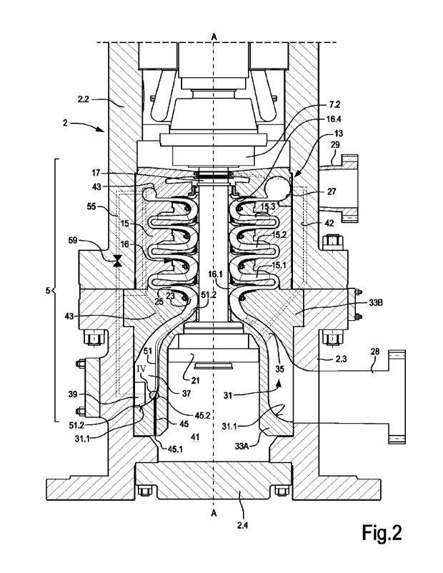
Fig.2 is an enlargement of the section of the motor-compressor shown in
Fig.1;
10 Fig.3 is a cross-sectional view according to line
in Fig.1;
Fig.4 is an enlargement of detail IV of Fig.2; and
Fig.5 is a flowchart of a method according to the present disclosure.
DETAILED DESCRIPTION
100171 A novel and useful centrifugal compressor is disclosed herein, in which
liquid
15 collected in the bottom area of the compressor is removed more
efficiently. The com-
pressor may be integrated with a motor, i.e. configured as a motor-compressor
having
a common casing housing both a motor and a compressor.
[0018] The compressor includes a gas inlet and a gas outlet, as well as a gas
flow
path extending from the gas inlet to the gas outlet. The gas flow is processed
through
20 one or more impellers and one or more diffusers. Gas is compressed by
adding kinetic
energy thereto by means of the rotating impeller(s) and by subsequently
slowing down
the gas flow in stationary diffuser(s). The compressor is configured as a
vertical com-
pressor, wherein (when the compressor is installed and in operation) the rotor
rotates
around a vertical axis. The gas inlet is located in the bottom area of the
compressor
25 and the gas outlet is placed at a level above the gas inlet. An inlet
plenum is provided
between the gas inlet and the impeller, or the first impeller if there are
more than one
impeller. Liquid possibly present in the gas flow accumulates in the bottom of
the inlet
plenum. To ameliorate drainage of a liquid phase from the inlet plenum, at
least one
suction tube is provided, which extends upwardly from the bottom of the inlet
plenum
30 towards the suction side of the impeller (or preferably the first
impeller, if there are
more than just one impeller). Suction generated by the impeller thus
propagates
-4-
CA 03160034 2022-5-30
WO 2021/115633
PCT/EP2020/025571
through the suction tube towards the bottom of the inlet plenum, where the
suction end
of the suction tube is located. Liquid from the bottom of the inlet plenum is
thus effi-
ciently removed by suction from the bottom of the inlet plenum and the
advancement
thereof through the gas flow path is promoted, such as to remove the liquid
phase
5 collected in the bottom area of the compressor.
100191 As mentioned above and as will become readily apparent from the
detailed
description below, the present disclosure relates to a vertical compressor,
i.e. a com-
pressor having a rotor adapted to rotate around a vertical axis when the
compressor is
in operation. In the present disclosure reference is made to the spatial
relationships of
10 various parts of the compressor. The terms "upper", "higher", "lower",
"top", "bot-
tom", "above", "below", "under", "upwards", "downwards" and the like, are
referred
to the position of the various components when the compressor is in operation,
i.e.
with the rotation axis in a vertical position, unless differently indicated.
The terms
"upstream" and "downstream" as used herein refer to the direction of the fluid
flow
15 through the compressor, unless differently indicated.
100201 Turning now to the drawings, Fig .1 illustrates a sectional view of a
motor-
compressor 1, taken along a plane containing a rotation axis A-A of the
compressor.
The motor-compressor 1 includes a casing 2, housing a motor section 3 and a
com-
pressor section 5. The casing 2 can in turn include a top closure 2.1, an
upper casing
20 portion 22, a lower casing portion 2.3 and a bottom closure 2A.
100211 The motor section 3 houses a driver for the compressor. Specifically,
in the
illustrated embodiment the motor section 3 houses an electric motor 7 having a
rotor
supported for rotation in the casing 2 around the rotation axis A-A. The rotor
of motor
7 can be supported by suitable bearings 9, 11. 1.n some embodiments the
bearings 9
25 and 11 can be active magnetic bearings. More specifically, the rotor of
motor 7 can
have an upper shaft end 7.1, housed for rotation in the upper bearing 9, and a
lower
shaft end 7.2 housed for rotation in the lower bearing 11.
100221 The compressor section 5 houses a compressor 13. The compressor 13 in-
cludes a stationary portion, commonly referred to also as the "compressor
bundle",
30 labeled 15 as a whole (see also Fig2). The stationary portion 15 of the
compressor 13
includes one or more diffusers for one or more impellers. The diffusers are
labeled
-5-
CA 03160034 2022-5-30
WO 2021/115633
PCT/EP2020/025571
15.1, 15.2 and 15.3. The compressor 13 further includes a rotor 16 arranged
for rotation
around the rotation axis A-A. The rotor includes a shaft 17 and a plurality of
impellers
16.1, 16.2, 16.3 and 16.4. The number of impellers and of diffusers is by way
of ex-
ample, and those skilled in the art will understand that several of the
advantages of the
5 compressor disclosed herein can be achieved also in single-stage
compressors, i.e.
compressors having a single impeller.
[0023] The shaft 17 of the compressor 13 is drivingly coupled to the shaft 7.2
of the
motor 7 and can be supported by bearing 11 and the bottom end thereof can be
sup-
ported by a bottom bearing 21, arranged under the rotor 16.
10 [0024] Each impeller has an impeller suction side and an impeller
delivery side. In
Fig.2 the impeller suction side of impeller 16.1 is labeled 23 and the
relevant impeller
delivery side is labeled 25. The impeller delivery side is fluidly coupled to
the first
diffuser 15.1.
[0025] The most downstream impeller 16.4 is fluidly coupled to a scroll 27,
which is
15 in turn in fluid communication with a gas outlet 29 of the compressor
13.
[0026] The compressor 13 further includes an inlet plenum 31, which extends
from
a gas inlet 28 towards the suction side of the first impeller 16.1. The inlet
plenum 31
extends from a bottom 31.1 towards a top of the inlet plenum, located in front
of the
suction side 23 of the impeller 16.1. As can be best appreciated from Fig.3,
the inlet
20 plenum 31 extends circumferentially around the rotation axis A-A of the
motor-com-
pressor 1 and has a tapered shape in a sectional view, with a narrower
transverse di-
mension at the top and a larger transverse dimension at the bottom.
[0027] In some embodiments, the outer boundary of the inlet plenum 31 is
defined
by the stationary portion 15 of the compressor 13, and the inner boundary of
the inlet
25 plenum 31 is defined between an axial inner body 33A, which forms a hub
of the inlet
plenum 31, and a shroud 33B, which surrounds the inner body 33A. The inner
body
33A and the shroud 33B are coupled to one another by struts 35. As shown in
Fig.2,
the struts 35 can have an aerodynamic profile, e.g. an airfoil profile, to
reduce head
losses in the gas flowing through the inlet plenum 31.
30 [0028] As mentioned above, the inlet plenum 31 is fluidly coupled to the
gas inlet
-6-
CA 03160034 2022-5-30
WO 2021/115633
PCT/EP2020/025571
28. Opposite the gas inlet 28 a fin 37 can be provided in the inlet plenum 31.
The fin
37 divides the inlet plenum 31 into two portions and forms a so-called
settling area or
settling chamber 39 at the bottom 31.1 of the inlet plenum 31, for the
purposes to be
described later on.
5 [0029] A gas flow path is thus formed in the motor-compressor 1, the gas
flow path
including the gas inlet 28, the inlet plenum 31, the impellers 16.1, 16.2,
16.3, 16.4 and
relevant diffusers 15.1, 15.2, 15.3, the scroll 27 and the gas outlet 29.
[0030] The inner body 33A forming the radially inner surface and the bottom
surface
of the inlet plenum 31 also defines a seat, in which the bottom bearing 21 is
housed.
10 The bottom bearing 21 can be an active magnetic bearing, similarly to
bearings 9 and
11.
[0031] The inner body 33A has an inner cavity and a liquid collection chamber
41 is
formed in and below the inner body 33A, between this latter and the bottom
closure
2.4 of the casing 2. The liquid collection chamber 41 can be adapted to
collect by
15 gravity liquid from the remaining portions of the compressor 5, through
drainage ducts,
one of which is shown by way of example in Fig.2 and labeled 43.
[0032] The liquid collection chamber 41 can be fluidly coupled with the inlet
plenum
31. The bottom of the liquid collection chamber 41, i.e. the lowermost point
thereof,
can be placed lower than the bottom of the inlet plenum 31, as shown in Figs.
1 and 2.
20 In some embodiments, the fluid connection between the liquid collection
chamber 41
and the inlet plenum 31 can be established through at least one communication
duct
45. The communication duct 45 has a lower inlet 45.1 in the liquid collection
chamber
41 and an upper outlet 45.2 in the inlet plenum 31. In preferred embodiments,
the upper
outlet 45.2 is arranged at a level lower than the bearing 21. By efficiently
aspirating
25 liquid away from the inlet plenum 31 in the manner described later on,
the liquid level
inside the liquid collection chamber 41 will thus always remain below the
bearing 21,
preventing the bearing 21 from being flooded.
[0033] As used herein, the terms "aspirate" and "aspirating" mean to "draw or
re-
move by suction".
30 [0034] In order to promote the flow of liquid from the liquid collection
chamber 41
-7-
CA 03160034 2022-5-30
WO 2021/115633
PCT/EP2020/025571
upwards, towards the bottom of the inlet plenum 31, in some embodiments a
pressure
line 42 places the liquid collection chamber 41 in fluid communication with a
source
of pressure, for instance a source of pressurized or partially pressurized
process gas.
The pressurized or partially pressurized process gas can be diverted from the
gas flow
5 path of the compressor 5, downstream of the first impeller 16.1. As shown
in Fig.2,
for instance, the pressure line 42 can be in fluid communication with the
scroll 27. In
other embodiments, the inlet end of the pressure line 42 can be connected to
the gas
outlet 29, or to any other portion of the gas flow path where the gas pressure
is higher
than in the inlet plenum 31. For instance, the inlet end of the pressure line
42 can be
10 arranged between the first or any subsequent impeller 16.1, 16.2, 16.3
and the impeller
downstream, or in any point between the most downstream impeller 16.4 and the
gas
outlet 29
100351 In some embodiments, the pressure line 42 can extend through one of the
struts 35 which connect the inner body 33A to the shroud 33B
15 100361 With the above arrangement, liquid contained in the fluid
processed through
the compressor collects by gravity in the liquid collection chamber 41 and
possibly at
the bottom of the inlet plenum 31, especially during periods of inactivity of
the motor-
compressor 1. At start-up the liquid phase shall be removed from the bottom of
the
compressor 13 (inlet plenum 31 and liquid collection chamber 41).
20 100371 During installation or after a prolonged period of inactivity,
the level of the
liquid collected in the bottom part of the compressor section 5 may rise up to
fill the
first and subsequent impellers 16.1, 16.2, 16.3, 16.4. When the compressor is
started,
the rotor 16 will rotate at slow speed and the liquid will be pumped through
the impel-
lers, while the compressor 13 operates as a pump. This pumping effect will
lower the
25 liquid level under the suction side 23 of the first impeller 16.1. The
rotation speed of
rotor 16 will increase and the reduction of the pressure above the free level
of the
liquid, in combination with the gas flow from the gas inlet 28 will cause
suction of the
liquid towards the impeller 16.1.
100381 However, removal of the liquid from the inlet plenum 31 becomes more
dif-
30 ficult as the level of the liquid in the inlet plenum 31 sinks.
100391 In order to ensure an efficient suction of the liquid from the bottom
of the
-8-
CA 03160034 2022-5-30
WO 2021/115633
PCT/EP2020/025571
inlet plenum 31, in the embodiment illustrated in the drawings a suction tube
51 is
provided, which has a first, lower suction end 51.1 and a second, upper
discharge end
51.2. As shown in particular in Fig.2, the lower suction end 51.1 is located
at the bot-
tom 31.1 of the inlet plenum 31. As understood herein "at the bottom" means
that the
5 suction end 51.1 can be located at the lowermost location inside the
inlet plenum 31,
or above the lowermost location, but preferably in the lower half of the inlet
plenum
31. The suction tube 51 extends upwardly towards the suction side 23 of the
first im-
peller 16 1 and the second, upper discharge end 51,2 thereof can be located
just in front
of the inlet of the first impeller 16.1, or at a distance therefrom. In any
event, the upper
10 discharge end 51.2 of the suction tube 51 is located in a position
where, when the
compressor 13 is in operation, a gas pressure is established which is lower
than the
pressure at the first, lower suction end 51.1 of the suction tube 51, thereby
aspirating
the liquid from the inlet plenum 31.
[0040] As a matter of fact, the suction tube 51 propagates the pressure
present at or
15 near the suction side of the impeller 16.1 towards the bottom of the
inlet plenum 31.
When liquid is present in the lower part of the inlet plenum 31, tending to
stagnate
therein, suction through the suction tube 51 will cause said liquid to be
transported
through the suction tube 51 towards the suction side 23 of the impeller 16.1.
An effi-
cient removal of the stagnating liquid will thus be obtained by suction.
20 [0041] In some embodiments, more than one suction tube 51 can be
provided.
[0042] In the exemplary embodiment shown in Figs. 1 and 2 the bottom 31.1 of
the
inlet plenum 31 has a variable height. More specifically, the bottom 31.1 of
the inlet
plenum 31 is at a lower level in the area at the gas inlet 28 and at a higher
level in the
opposite area, i.e. where the suction tube 51 is arranged. In other words, the
cross-
25 section of the inlet plenum 31 along planes containing the rotation axis
of the com-
pressor 13 varies around the axis. With this shape of the bottom 31.1 of the
inlet ple-
num 31 the energy of the incoming gas can be exploited to drag liquid
stagnating in
the lowermost part of the inlet plenum 31 towards the suction tube 51.
[0043] To promote the suction efficiency of the suction tube 51, the lower,
suction
30 end 511 thereof can be located in the settling chamber 39, formed as a
cavity in the
fin 37, for instance. As used herein, the term "settling chamber" or "settling
area" is
-9-
CA 03160034 2022-5-30
WO 2021/115633
PCT/EP2020/025571
understood as a volume filled with the fluid entering the compressor 13
through the
gas inlet 28, where the speed of the fluid is reduced and can be almost zero.
Here, the
kinetic energy of the fluid flow is thus converted into pressure energy,
facilitating the
suction of liquid through the suction tube 51.
5 [0044] In the embodiment shown in Figs 1, 2 and 3, the suction tube 51 is
formed
inside the fin 37, such that the number of components of the compressor 13 is
reduced
and the suction tube 51 is always maintained in a correct positioned inside
the inlet
plenum 31 opposite the gas inlet 28.
[0045] In some embodiments, in order to further promote suction of liquid from
the
10 bottom 31.1 of the inlet plenum 31, an ejector (i.e. an ejector pump)
can be provided
in or at the inlet end of the suction tube 51. The ejector is operated by
injecting a
pressurized fluid (e.g. pressurized or partly pressurized process gas) at the
first, lower
suction end 51.1 or in any suitable position along the suction tube 51. The
pressurized
gas can be diverted from the main gas flow along the gas flow path. For
instance, the
15 same pressure line 42 described above can be used for such purpose. In
the illustrated
embodiment, however, a separate pressure line 55 is provided, to feed the
ejector. The
pressure line 55 can be in fluid communication with a high-pressure portion of
the gas
flow path, for instance downstream one of the impellers 16.1, 16.2, 16.3 and
16.4 or
downstream of one of the diffusers 15.1, 15.2, 15.3. In other embodiments, the
pres-
20 sure line 55 is in fluid communication with the scroll 27, as shown in
Fig.2, or with
the gas outlet 29.
[0046] The pressure line 55 can be fluidly coupled to an ejector 57 (see
enlargement
in Fig.4), arranged in the suction tube 51 or at the suction end 51.1 thereof.
100471 When enhanced suction is required to remove liquid from the bottom 31.1
of
25 the inlet plenum 31, the pressure line 55 can be open to deliver
pressurized gas to the
ejector 57. When no pressurized gas is required, the pressure line 55 can be
closed, for
instance by way of a controlled valve 59 (Fig.2). This will improve the
overall effi-
ciency of the compressor 13.
[0048] With the above described motor-compressor 1 a method for removing
liquid
30 from the compressor 13 and start operation thereof can be performed as
follows. The
motor-compressor 1 is started when the compressor 13 is at least partly
flooded with
-10-
CA 03160034 2022-5-30
WO 2021/115633
PCT/EP2020/025571
liquid. For instance, liquid can be present in one or more of the following
areas of the
compressor 13: the liquid collecting chamber 41; the inlet plenum 31; one,
some or all
the impellers 16.1, 16.2, 16.3, 16.4.
100491 If liquid is present above the level of the upper discharge end 51.2 of
the
5 suction tube 51, liquid is pumped away through the impellers. Suction
generated at the
suction side of the impeller 16.1 is propagated through the suction tube 51 to
promote
suction of liquid from the bottom 31.1 of the inlet plenum 31 and from the
liquid col-
lection chamber 41 through the communication duet 45.
100501 The liquid collected in the lower portion of the compressor 13 is
gradually
10 removed until the full gas flow path is substantially free of liquid.
Liquid still contained
in the compressor 13 can collect in the liquid collection chamber 41,
remaining under
the level of the first, lower suction end 51.1 of the suction tube 51. The
method is
summarized in the flow chart of Fig.5.
100511 During operation of the motor-compressor 1, a liquid phase may be
present
15 in the gas entering the compressor 13 through the gas inlet 28, for
instance in form of
small droplets, or may condense in the gas flow along the gas flow path. The
compres-
sor 13 may include features (known per se) adapted to separate the liquid
phase from
the gaseous phase, such that such liquid phase collects by gravity in the
liquid collec-
tion chamber 41 and can be sucked away through the suction tube 51 Efficient
removal
20 of liquid both at start-up as well as during normal operation of the
motor-compressor
1 is thus obtained.
100521 While the invention has been described in terms of various specific
embodi-
ments, it will be apparent to those of ordinary skill in the art that many
modifications,
changes, and omissions are possible without departing form the spirit and
scope of the
25 claims. In addition, unless specified otherwise herein, the order or
sequence of any
process or method steps may be varied or re-sequenced according to alternative
em-
bodiments.
-11-
CA 03160034 2022-5-30