Note: Descriptions are shown in the official language in which they were submitted.
CA 03160462 2022-05-04
WO 2021/112700 PCT/PL2020/000082
Endoprosthesis
The subject of the invention is an endoprosthesis for implantation in bone
surgery,
in particular hip surgery, without the use of surgical cement.
The PL174976 patent demonstrates endoprosthesis for implantation in
osteoarticular
surgery composed of acetabulum and femoral head, which have sharp protrusions
on the
limiting surface, whereas the limiting surfaces of the acetabulum and femoral
head have the
form of a spherical cap, and the sharp protrusions with mutually parallel axes
have
correspondingly the form of polygonal needles of varying length placed
symmetrically, with
each needle contacting the adjacent edge needle at its base, whereas the outer
polygonal
needle protrusions placed respectively next to the supporting edge and the
supporting
surface have the shortest length, and the total area of the polygonal
protrusions and central
polygonal needle is advantageously seven times larger than the area of the
sphere on which
they were placed.
A German patent description DE 3443109 Al also demonstrates a solution in
which
the endoprosthesis is more securely fastened through the use of conical
irregularities
protruding from the limiting surface of the endoprosthesis and pointed towards
the
connecting surface of the bone. The conical irregularities are separate
elements, which have
a conical part and a cylindrical part set in the matrix of the acetabulum and
in the matrix of
the femoral head. For this purpose holes are made in the flat surfaces of the
femoral head
and on the annular offsets of the external spherical surface of the
acetabulum. These holes
weaken both the acetabulum and the femoral head of the endoprosthesis in a
lateral cross-
section, and simultaneously the conical irregularities set in them are at risk
of loosening,
which leads to unstable embedding of the endoprosthesis in the bone. In a
known solution,
DE 3443109 Al the conical irregularities are fully pressed into the spongy
bone, which
increases the contact area, which facilitates the embedding of the
endoprosthesis in the
bone material. The flaw of this solution is not using the possible optimum
bone-
endoprosthesis contact area, due to the fact that the conical irregularities
are placed in
regular spacing on flat surfaces of the femoral head and on the annular
offsets of the
external spherical surface of the acetabulum, moreover the flat contact
surface by directly
contacting the bone at the moment of implantation prevents the later growing
in of spongy
1
CA 03160462 2022-05-04
WO 2021/112700 PCT/PL2020/000082
bone in the form similar to natural, which would ensure good shock absorption
of loads on
the joint.
The CN105125324 invention demonstrates an improved metal acetabulum outer cup
with rough lamina for artificial hip join. The improved metal acetabulum outer
cup is
characterized in that the cup is made by casting or forging, and a rough
medical metal
lamina is formed on a corresponding surface, contacting with bones of a
patient, of the
acetabulum outer cup by material increase manufacturing.
The AU2015286971 invention relates to an acetabulum for a hip prosthesis,
comprising an inner cavity and a rear outer surface facing the bone. In order
to be able to
implant the acetabulum without using cement, at least some areas of the outer
surface are
porous and osseointegrative, and the acetabulum is made exclusively of a
ceramic material.
In the US20130190889 invention an artificial hip joint was presented
consisting of
multi-layer shell core composite structural components, which includes an
artificial
acetabular bone and an artificial femoral head, which are mutually matched
with each other.
The artificial acetabular bone has a multi-layer shell core composite
structure and is
constituted of a ceramic acetabular bone lining, transitional layers, an
acetabular bone shell
made of a porous metal or a porous alloy or a porous toughened ceramic. The
artificial
femoral head has a multi-layer shell core composite structure and is
constituted of a ceramic
spherical shell layer, a transitional layer and a toughened ceramic inner
core. The artificial
acetabular bone lining and the artificial femoral head spherical shell layer
of the hip joint
have high rigidity, anti-corrosion and anti-wear performance. In order to
improve adhesion
and stability the artificial layer of the acetabulum shell and internal layer
of the core off the
femoral head of the endoprosthesis have high strength and shock resistance. It
is a solution
which creates micropores.
In the EP1308141 invention a hip joint endoprosthesis is presented, provided
with a
plurality meridional incisions, which define as many segments elastically
flexible in the radial
direction. The inner surface of the socket is provided with one or more
grooves, parallel to
the proximal rim, wherein these grooves receive corresponding protrusions of a
joint insert.
The socket additionally comprises one or more frustoconical portions which
form bearing
surfaces for corresponding frustoconical portions of the joint insert. The
inner surface of the
socket bounds a polygonal seat which is adapted to engage with a polygonal
portion of the
joint insert by means of a form fit.
In the EP2338443 patent presents a fastening shell with a teeth structure
arranged in
an external side of a semi shell, and a milling tool for forming a shape of
teeth flanks. The
equator-side oriented flanks of the individual teeth form an angle of less
than 90 degrees
with a component axis such that barbed hook effect is developed in an equator.
A path of
the tool is curved for forming teeth gaps and formed such that the teeth of a
teeth row are
consecutively arranged in the teeth gaps and cutting edges of the teeth from
the equator
towards a pole do not overlap or have a gap of around 2 mm.
The RU2467724 patent discusses endoprosthesis which comprises a pivotally
connected cotyloid prosthesis and prosthesis of a proximal end of femoral bone
having a
stem for intraosseous introduction, a neck and a spherical head. On an
external surface of
2
CA 03160462 2022-05-04
WO 2021/112700 PCT/PL2020/000082
the head, there is a cylindrical section in the form of a flat. The endoprosth
esis has a
spheroidal internal cavity of a depth exceeding a half-radius of the head with
an input hole
less than the head diameter and equal to its diameter within the cylindrical
section to lock
and key the head in the cotyloid endoprosthesis. The cylindrical section faces
a junction of
the head and the neck at an angle approximately 33-61 to its axis. The head
diameter is 22-
38 mm, while the neck diameter is 13-14 mm. The invention may provide higher
reliability
and durability of endoprosthesis function after implantation.
The essence of the invention is a hip joint endoprosthesis for implantation in
bone
surgery of ball-and-socket joints, in particular hip joint, characterized in
that it consists of a
moving connection provided by the contact surface of two modules of the
endoprosthesis
femoral head and endoprosthesis acetabulum, whereas their surfaces which are
in contact
with the bone next to the joint have a shape similar to a sphere, on which
pins are placed,
with an axis principally parallel to the lengthwise axis of the
endoprosthesis, and at least two
cutting blades with an arc-shaped cross-section outline, creating a groove for
removal of the
products of cutting.
It is advantageous, when the sphere is a convex shell, on which pins are
located,
forming the endoprosthesis acetabulum, or when the shell is a concave shell,
on which pins
are located, forming the endoprosthesis femoral head.
It is also advantageous, when the endoprosthesis has on its external surface,
in the
zone of the lengthwise axis, advantageously rounded, porous supporting
surface.
It is also advantageous, when the pins are placed in the area outside of the
supporting surface 6, forming the limiting surface and when the pins are
placed on a
spherical surface forming the limiting surface.
Moreover it is advantageous when the cutting blades of the pins have an angle
of
application f within a range of 5-15 , advantageously 10 , angle of attack a
35-45 ,
advantageously 40 , and the wall thickness H of the cutting blade 3 wall
amounting to 0.25-
1 mm, advantageously 0.5 mm, and the H1 height of the cutting blade of the
pins is 2-3
times higher than the H2 height of the opposite wall 4 of the groove 5.
It is in particular it is advantageous when the supporting surface has a 02
diameter
with a value of 1/2-1/3 of the D1 diameter of the femoral head.
It is advantageous when the femoral head endoprosthesis has a cylindrical
elongation
with an A angle in relation to the centre point within a range of 30 to 50
degrees and when
the end of the grooves is situated in the zone of technological gripping
devices, and the
distance z between the bases of adjacent pins 2 is at least 100 micrometers.
It is also advantageous when the pins have a shape of a cone or a rounded cone
or a
truncated cone or a regular polyhedron.
It is also advantageous when the pins have smooth side surfaces or shaped side
surfaces.
3
CA 03160462 2022-05-04
WO 2021/112700 PCT/PL2020/000082
And it is also advantageous when the height of the pins on the surface of the
endoprosthesis acetabulum shell decreases from the edge to the supporting
surface, the
height of the pins on the surface of the convex endoprosthesis femoral head
shell decreases
from the central axis of the endoprosthesis to the external direction and when
the height of
the highest pin is approximately twice the height of the lowest pin.
It is particularly advantageous when the top points of the pins create a
surface with
an outline similar to the surface of the sphere on which they are placed.
It is moreover advantageous when the pins are placed on the external surface
of the
acetabulum and on the internal surface of femoral head.
It is advantageous when an insert is introduced on the internal spherical
surface of
the acetabulum endoprosthesis.
The use of the solution presented in the invention is expected to provide the
following technical and utility effects:
= maximum reduction of micro-movements and loosening of the acetabulurn and
cap,
due to the density of pins with a maximally increased adhesion surface in the
bone-
implant relationship,
= elimination of the use of glues/cements, which after some time cause stem
endoprostheses to loosen,
= appropriate distribution of forces between the bone and the
endoprosthesis, as well
as a much less invasive implantation procedure and the possibility of using in
patients
within a larger age range,
= much more advantageous growth of side (adhesive) surface due to the use
of a multi-
pin area,
= longer period of use of the endoprosthesis,
= relatively easy replacement in case repeated implantation is required,
= bringing the shape of the endoprosthesis closer to biological model,
= endoprosthesis may be implanted in patients with advanced osteoporosis
without
the use of surgical cement (glue),
= minimised implantation procedure minimises the degree of trauma to bone
tissue,
= the design of the endoprosthesis cap protects blood vessel which supply
blood to the
proximal end of the femoral bone,
The subject of the invention, in the example implementation was presented on
drawings, where fig. 1 presents a view of the acetabulum on the side of the
supporting
surface, fig. 2 presents a detail of fig. 1, fig. 3 presents a cross-section
of a cutting blade, and
fig. 4 a cross-section of the acetabulum, fig. 5 demonstrates a view of the
acetabulum, fig. 6
presents a detail of the acetabulum from fig. 5, fig. 7 presents a view of the
acetabulum on
the side of the supporting surface, fig. 8 demonstrates a detail of the
acetabulum from fig. 7,
4
CA 03160462 2022-05-04
WO 2021/112700 PCT/PL2020/000082
fig. 9 presents a cross-section of the cutting blade, fig. 10 presents a view
of the acetabulum,
fig. 11 presents a detail of the acetabulum from fig. 10, fig. 12 presents a
view of the femoral
head, fig. 13 presents a detail of the view from fig. 12, fig. 14 demonstrates
a cross-section
of the femoral head, fig. 15 presents a view of the femoral head on the side
of the limiting
surface, fig. 16 presents a detail of the view from fig. 15, fig. 17 presents
a view of the
femoral head, and fig. 18 a detail of the view of the femoral head from fig.
17, fig. 19
presents a view of the femoral head on the side of the limiting surface, fig.
20 a detail of the
femoral head from fig. 19, fig. 21 presents a cross-section of the pins, and
fig. 22
demonstrates a fragment of the cross-section of the femoral head, fig. 23 a
cross-section of
the pin, fig. 23a presents a pin in the form of a cone, fig. 23b a pin in the
form of a rounded
cone, fig. 23c a pin in the form of a prism, fig. 23d a pin in the form of a
cuboid, fig. 24
presents a fragment of the cross-section of the acetabulum, fig. 25 presents
an isometric
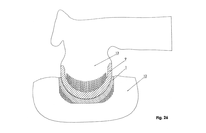
view of the acetabulum on the side of contact of friction couple, fig. 26
presents a cross-
section of the endoprosthesis acetabulum and femoral head system embedded on
bone
surfaces, fig. 27 presents a cross-section of the friction couple, and fig. 28
presents a cross-
section of the femoral head endoprosthesis with a demonstrated angle of
elongation of the
cylindrical surface.
Hip joint endoprosthesis for implantation in bone surgery of ball-and-socket
joints, in
particular hip joint, consists of a moving connection provided by the contact
surface 10 of
two modules of the endoprosthesis femoral head 9 and acetabulum 1. The
surfaces of the
endoprosthesis femoral head 9 and acetabulum 1 which are in contact with the
bone next to
the joint have a shape similar to a sphere, on which pins 2 are placed. The
pins 2 have an
axis in principle parallel to the longitudinal axis of the endoprosthesis and
at least two
cutting blades 3 with an arc-shaped cross-section outline are formed, creating
a groove 5 for
removal of the products of cutting. In the endoprosthesis the sphere is a
convex shell, on
which pins 2 are located, forming the endoprosthesis acetabulum 1. The sphere
is a concave
shell, on which pins 2 are located, forming the endoprosthesis femoral head 9.
The
endoprosthesis has on its external surface, in the zone of the lengthwise
axis,
advantageously rounded, porous supporting surface 6. The pins 2 are placed in
the area
outside of the supporting surface 6, forming the limiting surface 11 and are
placed on a
spherical surface forming the limiting surface 11. In the endoprosthesis the
cutting blades 3
have an angle of application 13 within a range of 5-15 , advantageously 10 ,
angle of attack a
35-45', advantageously 40 , and the wall thickness H of the cutting blade 3
wall amounting
to 0.25-1 mm, advantageously 0.5 mm, and the H1 height of the cutting blade 3
is 2-3 times
higher than the H2 height of the opposite wall 4 of the groove 5. The
supporting surface 6
has a D2 diameter with a value of 1/2-1/3 of the D1 diameter of the femoral
head 1. The
femoral head endoprosthesis has a cylindrical elongation with an X angle in
relation to the
centre point within a range of 30 to 50 degrees. In the endoprosthesis the end
of the
grooves 5 is situated in the zone of technological gripping devices 8. The
distance between
the bases of adjacent pins 2 is at least 100 micrometers. The pins 2 have a
shape of a cone or
a rounded cone or a truncated cone or a regular polyhedron. Moreover the pins
2 have
smooth side surfaces or shaped side surfaces. The height of pins 2 decreases
from the edge
to the supporting surface and from the central axis of the endoprosthesis to
the external
CA 03160462 2022-05-04
WO 2021/112700 PCT/PL2020/000082
direction. The height of the highest pin 2 is approximately twice the height
of the lowest pin
2. The top points of the pins 2 create a surface with an outline similar to
the surface of the
sphere on which they are placed. The pins 2 are placed on the external surface
of the
acetabulum 1 and on the internal surface of femoral head 9. Additionally an
insert 14 is
introduced or not on the internal spherical surface of the endoprosthesis
acetabulum 1.
The endoprosthesis consists of acetabulum 1 and femoral head 9, which on their
limit
surfaces in the form of spherical shells have polygonal needle protrusions in
the form of pins
2 with parallel axes and varying length, the total area of which is a multiple
of the joint area,
whereas the minimum distance "z" between the bases of pins 2 is 100
micrometers, used in
order to enable growth of trabeculae. The bases of pins 2 are not tangential.
The axes of pins
2 are perpendicular to the plane of the supporting surface of the femoral head
and of the
supporting surface of the acetabulum 1, respectively. Additionally in order to
reduce the
abrasive wear of the friction couple of the acetabulum 1 and femoral head 9 of
the hip joint
endoprosthesis an insert 14 is introduced or not on the internal spherical
surface of the
endoprosthesis acetabulum 1 made of non-metallic material.
A precondition for the operation of the system is the fitting of the shape and
size of
the endoprosthesis femoral head 9 to the size and shape of the endoprosthesis
acetabulum
1 in order to ensure the correct operation of the friction couple.
The endoprosthesis femoral head 9 is placed in the grips of an external device
providing rotational movement, not shown on the drawing. This device moves the
endoprosthesis around its angle of symmetry with a specific speed adapted to
the machined
material. The endoprosthesis, in the form of femoral head 9 is rotated, using
the cutting
blades 3 to remove bone tissue 7, which falls into the groove 5 between the
wall of the
cutting blade 3, and the wall 4 of the groove 5 or between the wall of the
cutting blade 3 and
the pins 2. The bone tissue 7 is moved by the pressure exerted by the newly
cut bone tissue
7 between the wall of the cutting blade 3 and the wall 4 of the groove 5 or
between the wall
of the cutting blade 3 and the pins 2 out of the endoprosthesis, through the
direct surface of
the contact of the endoprosthesis with the bone tissue 7 surface. This process
lasts until an
optimum position of the endoprosthesis is obtained. The endoprosthesis causes
a slight
filling of the space between the pins 2 with small fragments of bone, which
will feed the
process of bone reconstruction and stabilisation of the endoprosthesis. After
removing the
diseased tissue of the joint connection and using the cutting blades 3 to
obtain a shape
similar to the outline created by the tips of the pins 2, the endoprosthesis
is disconnected
from the device providing rotational movement, not shown of the drawing, and
then is
placed on the previously prepared surface and gradually inserted into the
spongy bone
space, in parallel to the axis of symmetry of the femoral head 13 of the
joint. The supporting
surface 6 does not contact the perlosteum, the cortical substance and the
spongy substance,
into which the pins 2 at a distance longer than the plane of the supporting
surface 6 are
simultaneously inserted. The pins do not penetrate the spongy bone fully, to
enable
releasing of excessive intraosseous fluid pressure. The space between the pins
2 which is not
6
CA 03160462 2022-05-04
WO 2021/112700 PCT/PL2020/000082
filled with bone tissue 7 in this process will be filled with osteoblasts in
the process of tissue
regeneration, which will grow during the convalescence period.
The implantation method for acetabulum endoprosthesis is similar to the
implantation of the femoral head, whereas the acetabulum endoprosthesis is
implanted in
such a manner that the supporting surface 6 of the truncated limiting surface
adheres to the
bone in a plane perpendicular to the axis of the central acetabulum 1 of the
bone and be
placed in a manner symmetric to this axis, and polygonal pins 2 in the area of
the spherical
belt on the limiting surface 11 of the endoprosthesis acetabulum 1 are
partially sunk into the
spongy structure of the bone. The remaining space between the polygonal needle
protrusions 2 not sunk into the spongy bone, up to the limiting surface 11 are
filled with
osteoblasts which grow during the convalescence period as a result of lack of
movement
between the endoprosthesis acetabulum and the bone 12. The supporting surface
6 with a
slight rounding protects the implanting process against possible trauma to
blood vessels
present in the direct vicinity of the cut tissue.
Additionally in order to reduce the abrasive wear of the friction couple of
the
acetabulum land femoral head 9 of the hip joint endoprosthesis an insert 14 is
introduced
or not on the internal spherical surface of the endoprosthesis acetabulum 1
made of non-
metallic material.
A precondition for the operation of the system is the fitting of the shape and
size of
the endoprosthesis femoral head 9 to the size and shape of the endoprosthesis
acetabulum
1 in order to ensure the correct operation of the friction couple.
The pins 2 are partially sunk in the bone tissue 7, advantageously to half
their height,
in order to allow osteoblasts to grow on the surface which is not sunk in the
bone tissue 7.
7
CA 03160462 2022-05-04
WO 2021/112700
PCT/PL2020/000082
Designation
1 ¨ acetabulum
2 ¨ pin
3 ¨ cutting blade
4 ¨ wall
¨ groove
6 ¨ supporting surface
7 ¨ bone tissue
8 ¨ technological gripping device
9 ¨ femoral head
¨ friction couple contact surface
11 ¨ limiting surface
12 ¨ pelvic bone
13 ¨ femoral head
14 ¨ insert
H ¨ cutting edge 3 wall thickness
H1 ¨ cutting edge 3 height
H2 ¨ opposite wall 4 height
a ¨ angle of attack angle of application
¨ angle of application
¨ angle of elongation of the femoral head 9 endoprosthesis body
D1 ¨ diameter of the femoral head 1
D2 ¨ diameter of the supporting surface 6
z ¨ distance between pins 2
8