Note: Descriptions are shown in the official language in which they were submitted.
WO 2021/118345
PCT/NL2020/050764
- 1 -
Underwater Optical Communication Unit
Technical Field
[0001] The invention relates to an underwater wireless optical
communication unit, and to a
method for using such a unit.
Background Art
[0002] In many underwater applications, for instance in subsea
ecological monitoring, geology,
oil and gas extraction, and defence applications, there is an increasing need
for communicating
data between two submerged entities. Communication technologies that rely on
light propagating
freely through the water provide high data rates and allow exchange of data
between arbitrary
pairs of transmitting and receiving devices (e.g. underwater monitoring units,
nearby underwater
vehicles, or other artificial underwater structures). The small carrier
wavelengths for optical data
signals allows construction of small units and communication components with
high resolution
(e.g. a factor 10,000 compared to acoustic communication), low latency, and
fast update rates.
[0003] Propagation of light underwater is nevertheless severely
limited compared to
propagation in air or free space. For wireless communication transmission
underwater, it is
preferred to use optical signals with wavelengths ranging from 300 nanometres
to 600
nanometres, to anticipate for the selective propagation behaviour of light
through water resulting
from absorption and scattering by the water and/or particulates in the water.
[0004] The maximum communication signal distance between an
optical transmitter and
receiver in an optical underwater communication system that can be bridged
depends on
available optical power, communication bandwidth, sensitivity of the receiver,
directivity of the
receiver and transmitter, and attenuation of the electromagnetic field along
the propagation path.
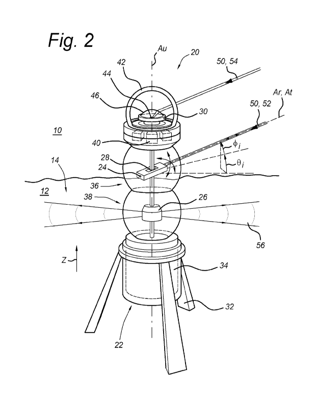
For any optical communication system, the required power is proportional to
the data rate, but the
gain of the system is inversely proportional to the required power.
[0005] It may be advantageous to use a directional communication
system with high directivity
in order to increase maximum communication range and data rate, and/or to
improve power-to-
range efficiency. The latter may be particularly desired in self-powered
subsea communication
devices, which may be designed to function autonomously underwater for a
prolonged time to
minimize deployment, calibration, and retrieval operations.
[0006] In any case, the transmitter and/or receiver in
directional systems need to be properly
pointed and mutually aligned with a receiver and/or transmitter of another
system, to establish a
signal link. A small error in alignment of a transmitter of one unit and a
receiver of another unit
may mean that only a weak signal or even no signal will be received at the
other unit. The correct
pointing angles may be found by scanning the surroundings and searching for
reception maxima
with the transmitting and/or receiving units, but this requires considerable
time, especially for
highly directive transmitting and/or receiving units.
[0007] It would be desirable to provide an underwater wireless
communication unit that allows
rapid autonomous establishment of a high-bandwidth and/or high-range
communication link with a
CA 03160707 2022- 6-3
WO 2021/118345
PCT/NL2020/050764
- 2 -
nearby unit, vehicle, or structure.
Summary of Invention
[0008] Therefore, according to a first aspect of the invention,
there is provided a
communication unit for wireless optical communication in an underwater
environment. The unit
comprises a housing, a communication transceiver, an adjustment mechanism, and
a processor
device. The housing accommodates the communication transceiver. The
communication
transceiver includes an optical signal detector that has a directive gain with
a main lobe centred
on a receiver directivity axis, and is configured to receive an optical
communication signal
approaching the unit through the main lobe. Alternatively or in addition, the
communication
transceiver includes an optical signal generator that has a directive gain
with a main lobe centred
on a transmitter directivity axis, and is configured to emit an optical
communication signal along
the transmitter directivity axis and away from the unit. The adjustment
mechanism is configured to
adjust an orientation of the receiver directivity axis and/or an orientation
of the transmitter
directivity axis relative to the housing. The processor device is configured
to determine at least
one directional coordinate (e.g. azimuth and/or elevation angle) for a light
signal approaching the
communication unit from a light source located in the vicinity. The processor
device is further
configured to control the adjustment mechanism to automatically adjust and
align the orientation
of the receiver directivity axis with the determined at least one directional
coordinate. Alternatively
or in addition, the processor device is configured to control the adjustment
mechanism to
automatically adjust and align the orientation of the transmitter directivity
axis with the at least one
directional coordinate.
[0009] The unit may include an optical communication transmitter
and/or an optical
communication receiver that are/is directional and repositionable relative to
a stationary part of the
housing. The processor device is configured to determine one or more
directional coordinates of
the received light signal, based on data acquired by another measurement
source, for instance
data from an on-board photogrammetric camera. Based on the determined
coordinate(s), the
optical communication receiver and/or transmitter can be realigned
automatically, without wasting
time and energy on scanning the surroundings for incoming signals with the
directional receiver,
or wasting power on optical transmissions towards directions where the
recipient is not located. A
communication link between the unit and the target can thus be quickly
established or recovered
after a link failure.
[0010] The directivities of the optical signal generator and
detector represent the maximal
values of their respective directive radiation or detection gain functions.
The directive gain is a
ratio of the power per unit solid angle radiated/received in a particular
direction to the average
power value over all directions. An optical transmitter and/or receiver with a
directivity D of 10 (DdB
= 10dB relative to an isotropic reference radiator Di=1) or more may yield
significant
improvements in underwater communication channel performance. Transceiver
and/or receiver
directivities of 30 (Dde7-- 15dB), 300 (Dde =-- 25dB), or even 3000 (Dde ==---
35dB) may be preferred.
CA 03160707 2022- 6-3
WO 2021/118345
PCT/NL2020/050764
- 3 -
[0011] In embodiments wherein the communication receiver and
transmitter are both
directional and repositionable, the optical signal generator and detector may
be mechanically
fixed to each other, and integrated to form one repositionable transceiver
unit. This allows the use
of a single actuator device for simultaneously repositioning the transmitter
and receiver main
lobes with the directional coordinate(s). Alternatively, the optical signal
generator and detector, as
well as their adjustment mechanisms, may be formed as distinct devices that
are accommodated
in distinct housings and which are independently repositionable. This allows
the main lobes of the
directional transmitter and receiver to be aligned with different targets
(e.g. to relay received
signals from a nearby underwater vehicle to another communication unit, or
vice versa).
[0012] In embodiments, the communication unit comprises an underwater
imaging device,
configured to acquire image data of the light signal. The processor device may
then be configured
to receive the image data from the imaging device, to determine the
directional coordinate(s) for
the light signal relative to the imaging device, and to control the adjustment
mechanism to
automatically adjust and align the orientation of the respective directivity
axis with the at least one
directional coordinate.
[0013] The imaging device and position detection capability
allow imaging of a light emitting
target in the vicinity, and determination of directional coordinate(s) for the
target (e.g. azimuth
and/or elevation angle, or direction cosines). The underwater imaging device
may be formed by
an omnidirectional photogrammetric camera with an ultra-wide field of view (UW-
FOV), preferably
with an azimuthal coverage of 360 and an elevational coverage of at least -20
to +30 , for
instance of -20 to 90 , or even of -500 to 90 .
[0014] In embodiments, the housing extends along a nominal unit
axis. The unit may comprise
an optical system that defines a focal plane substantially parallel with the
unit axis, such that the
optical signal detector and/or generator of the communication transceiver is
located in the focal
plane, and the corresponding directivity axis is transverse to the unit axis.
The adjustment
mechanism may include a linear actuator for moving the optical signal detector
and/or the optical
signal generator in the focal plane relative to the optical system and
parallel with the unit axis, to
deflect the directivity axis along an elevation direction. The processor
device may then be
configured to determine an elevation angle for the received light signal
relative to the housing, and
to control the linear actuator to adjust the orientation of the respective
directivity axis and align this
orientation with the determined elevation angle.
[0015] The optical system may be formed by a system of lenses, mirrors, or
combination
thereof. Power usage can be significantly reduced by using a linear actuator
for moving the
transmitting and/or receiving elements relative to the optical system and
along the focal plane
thereof, to change the directivity axis of the transceiver. Preferably, this
actuator mechanism is
used for adjusting the transceiver directionality in elevation directions.
[0016] In a further embodiment, the housing comprises a base,
and the adjustment mechanism
further includes a rotary stage that supports the optical signal detector
and/or generator of the
communication transceiver in a rotatable manner about the unit axis and
relative to the base. The
processor device may then be configured to determine an azimuth angle for the
received light
CA 03160707 2022- 6-3
WO 2021/118345
PCT/NL2020/050764
- 4 -
signal relative to the housing, and to control the rotary stage to adjust and
align the orientation
(e.g. pan angle) of the respective directivity axis with the determined
azimuth angle.
[0017] Preferably, the rotary stage supports both the imaging
device and the optical signal
detector and/or generator of the communication transceiver, in a jointly
rotatable manner relative
to the base. The unit may for instance define two opposite distal ends that
are intersected by the
nominal unit axis. The base may be located at one distal end, and the imaging
device may be
located at the opposite distal end and be rotatable relative to the base about
this unit axis. The
imaging device may be rotationally symmetric about the unit axis. The imaging
device may for
instance be formed by an omnidirectional photogrammetric camera with an
azimuthal coverage of
360 and an optical centre that faces along the unit axis and away from the
base.
[0018] In embodiments, the main lobe of the optical signal
detector and/or the optical signal
generator corresponds to a pencil beam distribution that is centred on the
corresponding
directivity axis. The processor device may be configured to determine an
azimuth angle and an
elevation angle for the received light signal relative to the housing. The
adjustment mechanism
may then comprise a pan-tilt actuator for adjusting an orientation (e.g. pan
and tilt angles) of the
pencil beam distribution relative to the housing to substantially align the
directivity axis with the
determined azimuth and elevation angles.
[0019] The main lobe of the transmitter and/or the receiver may
have a pencil beam profile,
which has narrow beam widths in both angular directions (e.g. pan, tilt)
relative to the central
directivity axis. The optical signal generator may for instance comprise a
laser source for emitting
an optical communication signal with a pencil beam-shaped directive
transmitter gain distribution.
[0020] In embodiments, the optical signal detector forms a multi-
region detector defining
multiple sensor regions, with each sensor region being configured to sense
light and to generate a
light detection signal proportional to the received light intensity
independently of the other sensor
regions. This detector may for instance be a quadrant detector with four
sensor regions that are
tiled in a mutually adjoining pattern, these regions having corners that meet
in a central common
vertex. A controller (e.g. the processor) may then be present and configured
to adjust an
orientation of the receiver directivity axis (e.g. by controlling the pan-tilt
actuator), in order to
centre a cross-sectional projection of the received beam associated with the
optical
communication signal onto the central common vertex of the sensor regions. The
adjustment
mechanism may be controlled based on comparison of the (potentially different)
detection signals
from the distinct sensor regions, and striving to reduce an imbalance between
those detection
signals. When all sensor regions (e.g. quadrants) generate the same detection
amplitude, the
device may be considered pointed at the transmitting light source.
Advantageously, detection
signals from the sensor regions of the multi-region detector will be
correlated, whereas noise of
the individual sensor regions will be uncorrelated.
[0021] In a further embodiment, the communication unit further
includes an optical system (e.g.
lenses and/or mirrors) for focussing an incoming beam associated with the
optical communication
signal onto the multi-region detector. The unit may also include a further
actuator, which is
configured to adjust a linear position of a focal point of the optical system
along the receiver
CA 03160707 2022- 6-3
WO 2021/118345
PCT/NL2020/050764
- 5 -
directivity axis and relative to the multi-region detector. The controller may
then be configured to
control the further actuator and to adjust this relative linear position, so
that the incoming beam
will be projected out of focus onto the multi-region detector and will cover
all sensor regions to
facilitate comparison between the detection signals.
[0022] In yet a further embodiment, the communication unit is configured to
operate in a
reception beam follower mode> This mode may be activated in case the optical
signal is coming
from a source that is gradually moving relative to the communication unit
(e.g. from a transceiver
mounted on an ROV). In this mode, the controller continuously compares
detection amplitudes
generated by the sensor regions, and adjusts the position of the optical
system relative to the
multi-region detector in order to maintain an out-of-focus state and ensure
that the received light
beam will continue to impinge on all sensor regions of the detector and allow
repeated
comparison of the signal amplitudes from all sensor regions. The controller
uses the signal
differences resulting from the comparison to drive the actuator mechanism and
adjust the
orientation of the receiver and optical system relative to the base of the
unit so as to stay pointed
at the moving light source.
[0023] In embodiments, the main lobe of the optical signal
detector and/or the optical signal
generator corresponds to a fan beam distribution that is centred on the
corresponding directivity
axis and is strongly bundled in an azimuth direction. The processor device may
be configured to
determine only an azimuth angle for the received light signal relative to the
housing. The
adjustment mechanism may then comprise a pan drive for adjusting an
orientation of the fan
beam distribution relative to the housing to substantially align the fan beam
distribution with the
determined azimuth angle.
[0024] The main lobe of the transmitter and/or the receiver may have a fan
beam profile, which
has a relatively narrow beam width in one angular direction and a relatively
wide beam width in
another angular direction, both directions defined relative to the directivity
axis. The main lobe
may be oriented such that the wide beam dimension extends substantially along
the rotation axis
of the pan drive, and that the narrow beam dimension substantially corresponds
with the
azimuthal repositionability by the pan drive. In this case, only a pan drive
may suffice to align the
fan beam with the determined azimuth angle associated with the observed
target, to benefit from
the increased transmitter and/or receiver sensitivity. The optical signal
generator may for instance
comprise a laser line generator for emitting an optical communication signal
with a fanbeam-
shaped gain distribution.
[0025] In embodiments, the optical signal detector and the
optical signal generator are fixed
relative to each other and form an integrated transceiver unit. The adjustment
mechanism may
then comprise an actuator for simultaneously adjusting the main lobes and
aligning the
orientations of the directivity axes with the at least one directional
coordinate.
[0026] In embodiments, the communication unit comprises a
further light source that is
configured to omnidirectionally emit at least one of an optical beacon signal
and a further optical
communication signal. The unit may include a separate omnidirectional light
source for
temporarily emitting light in all directions and allow a similar unit in the
vicinity to initially localize
CA 03160707 2022- 6-3
WO 2021/118345
PCT/NL2020/050764
- 6 -
this unit using its camera and processor, to allow the other unit to direct
its communication
transmitter and/or receiver towards the first unit. The further light source
may be a beacon light
that may radiate in a continuous manner, or be part of an additional
omnidirectional optical
communication transceiver.
[0027] According to a second aspect, and with the advantages and effects
described herein
above with reference to the first aspect, there is provided a method for using
a communication
unit according to the first aspect. The method comprises:
- deploying the communication unit and an underwater vehicle underwater, at
non-coinciding
positions and within optical communication range;
- emitting an optical signal with the underwater vehicle;
- determining at least one directional coordinate for the received optical
signal;
- adjusting a directivity axis of the optical signal detector and/or
optical signal generator of the
communication transceiver relative to the housing, to align the orientation of
the directivity axis
with the at least one directional coordinate;
- establishing a wireless optical communication link between the communication
transceiver of the
unit and a communication transceiver of the underwater vehicle;
followed by at least one of:
- controlling the underwater vehicle (e.g. by a shore-based pilot) via the
communication unit and
the established communication link, to let the underwater vehicle execute
intervention or
inspection operations;
- transmitting data acquired by the communication unit via the established
communication link to
the underwater vehicle, and
- receiving, with the communication unit, data from the underwater vehicle,
and streaming the
received data with the communication unit to a remote control station.
[0028] The underwater vehicle may for instance be an autonomous underwater
vehicle (AUV)
or a remotely operable vehicle (ROV). The unit may form part of a wireless
network of deployed
communication units, and/or be connected to a wired underwater network. The
wireless optical
link established between the vehicle and the communication unit allows data
from the vehicle to
be streamed via the unit back to shore. Alternatively or in addition, the link
allows the vehicle to be
remotely controlled to execute intervention or inspection tasks. Alternatively
or in addition, the link
allows the vehicle to access data acquired by the unit.
[0029] In an embodiment, the communication unit comprises an
underwater imaging device.
Determining the at least one directional coordinate for the received optical
signal may then
comprise receiving the optical signal with the imaging device.
[0030] In a further embodiment, the data acquired by the communication unit
is image data of
the surroundings of the unit acquired by the imaging device. The vehicle may
for instance be an
ROV that is used to perform inspection, repair, or maintenance (IRM) on subsea
oil and gas
assets. The image data may be streamed in real time to the ROV via the
communication link,
which allows the ROV pilot to obtain additional visual information of the
scene from another
perspective.
CA 03160707 2022- 6-3
WO 2021/118345
PCT/NL2020/050764
- 7 -
Brief Description of Drawings
[0031] Embodiments will now be described, by way of example
only, with reference to the
accompanying schematic drawings in which corresponding reference symbols
indicate
corresponding parts. In the drawings, like numerals designate like elements.
[0032] Figure 1 schematically shows an embodiment of an underwater wireless
communication
unit;
[0033] Figure 2 schematically shows the communication unit from
claim 1 in more detail;
[0034] Figure 3a schematically shows an underwater wireless
communication unit according to
another embodiment;
[0035] Figure 3b shows details of part of the communication unit from
figure 3a;
[0036] Figure 4 schematically shows an underwater wireless
communication unit according to
yet another embodiment, and
[0037] Figures 5-12 schematically show optical systems for
transmitters and/or receivers in
various embodiments.
[0038] The figures are meant for illustrative purposes only, and do not
serve as restriction of
the scope or the protection as laid down by the claims.
Description of Embodiments
[0039] The following is a description of certain embodiments of
the invention, given by way of
example only and with reference to the figures.
[0040] Figure 1 schematically shows a perspective view of an
exemplary communication unit
20 and an underwater vehicle 16. The unit 20 and the vehicle 16 are deployed
in a body of
seawater 10 at distinct positions but within optical communication range. The
unit 20 is deployed
in a stationary manner on a surface 14 of a seabed 12, with a nominal unit
axis Au that is
substantially perpendicular to the surface 14. The vehicle 16 remains moveable
through the water
10, and free to change its position and orientation relative to the surface
14.
[0041] The unit 20 comprises a housing 22, which accommodates various
electronic
components 24, 26, 30 in a watertight and pressure resistant manner. A
directional
communication transceiver 24 and an omnidirectional communication transceiver
26 are
accommodated in an optically transparent medial part of the housing 22. An
underwater imaging
device 30 is located in an optically transparent spherical dome on a top side
of the housing 22.
This imaging device 30 is configured to acquire image data of objects and
light sources in the
unit's vicinity. In deployed state, the imaging device 30 and transceivers 24,
26 protrude above
the surface 14, to provide line of sight to the vehicle 16 and to other units
20 in the vicinity (if
present).
[0042] In this example, the vehicle 16 is a ROV or UAV that
includes a wireless optical
transceiver 18, which is configured to emit optical communication signals 50
and to receive optical
communication signals 52 from transceivers 24 of nearby observation units 20.
The transceivers
18, 24, 26 of the communication unit 20 and the vehicle 16 are adapted to
cooperate and
establish optical communications links with different data rates and quality.
CA 03160707 2022- 6-3
WO 2021/118345
PCT/NL2020/050764
- 8 -
[0043] Figure 2 shows a more detailed view of the communication
unit 20 from figure 1. The
housing 22 of unit 20 has an elongated shape that extends along and is centred
on the unit axis
Au. The housing 22 comprises a base 32 with a power supply 34 at one distal
end of the housing
22, as well as an imaging device 30 that is stationary relative to the base 32
but located at an
opposite distal end of the housing 22.
[0044] This imaging device 30 may be formed by an omnidirectional
photogrammetric camera
that is accommodated inside a hyper-hemispherical dome 42 of optically
transparent material.
The camera 30 has an azimuthal coverage of 360 and an optical centre that
faces upwards
along the unit axis Au and away from the base 32. The camera 30 includes a
digital imaging
sensor 44 and a fish-eye lens 46 for receiving and refracting incoming rays of
light from the unit's
surroundings, and projecting this light onto the sensor 44. The fish-eye lens
46 confers an
omnidirectional UW-FOV upon the camera 30, which allows instantaneous imaging
of a large
portion of the surroundings in which underwater vehicles 16 and other units
20' are expected to
reside. The camera 30 is adapted to acquire image data of light signals 50, 54
approaching the
communication unit 20 from light sources 18, 19 located in the vicinity. These
signals may for
instance be beacon signals 54 from a vehicle beacon light 19, or communication
signals 50 from
the vehicle's optical transceiver 18.
[0045] The directional communication transceiver 24 includes an
optical signal detector that
has a directive gain with a main lobe centred on a receiver directivity axis
Ar. This detector is
configured to receive an optical communication signal 50 approaching the unit
through the main
lobe. The directional transceiver 24 also includes an optical signal generator
that has a directive
gain with a main lobe centred on a transmitter directivity axis At. This
generator is configured to
emit an optical communication signal 52 along the transmitter directivity axis
and away from the
unit 20. The main lobes of the optical detector and generator correspond to
pencil beam
distributions, which are centred on the respective directivity axes Ar, At.
The optical detector and
generator are aligned with and fixed relative to each other, to form an
integrated transceiver unit
24 in which the main lobes overlap and the directivity axes Ar, At coincide.
[0046] The unit 20 includes an adjustment mechanism 28, which is configured to
adjust an
orientation of the signal generator and detector relative to the housing 22,
so that the orientation
of the directivity axes Ar, At can be changed relative to the housing 22. In
this example, the
adjustment mechanism 28 is a pan-tilt actuator, adapted for simultaneously
adjusting the pan and
tilt angles of the pencil beam distributions and directivity axes Ar, At
relative to the housing 22
along azimuth and elevation directions.
[0047] The processor device 40 is configured to receive the image data from
the camera 30,
and to determine directional coordinates for the light signal relative to the
camera 30. Via initial
calibration procedures, a pixel region where a received light signal 50, 54
hits the sensor 44 can
be associated with directional coordinates relative to a local reference frame
defined with respect
to the camera 30. In this example, the directional coordinates are the
elevation angle Oi and
azimuth angle cPi. Alternative implementations may instead use directional
cosines, or another
angular coordinate system. Based on the directional coordinates, the processor
device 40 can
CA 03160707 2022- 6-3
WO 2021/118345
PCT/NL2020/050764
- 9 -
control the pan-tilt actuator 28 to automatically reposition the optical
generator and detector, and
align the orientation of the directivity axes Ar, At with the directional
coordinates (I)i, Oi. This
automatic alignment of the directional transceiver 24 allows a communication
link between the
unit 20 and the communication device of an observed target (e.g. the vehicle
16 or another unit
20') to be quickly established, or recovered after a link failure.
[0048] In view of the slight displacement between the camera 30
and the directional transceiver
24 along the unit axis Au, the elevation angle of the directional transceiver
24 may have to be
adjusted slightly upwards to improve performance. The amount of correction
depends on the
distance to the target, and may for instance be determined by ranging
techniques.
[0049] Figures 1 and 2 further illustrate methods for wireless optical
communication between a
unit 20 and a underwater vehicle 16 within optical communication range. The
camera 30 of the
unit 20 acquires image data of the beacon signals 54 emitted by the vehicle's
light beacon 19.
The unit's processor device 40 determines directional coordinates cl)i, ei for
the light beacon 19
relative to the reference frame of the camera 30. The processor 40 then
controls the pan-tilt
actuator 28, to re-orient the transceiver 24 relative to the housing 22 so
that the main lobes and
directivity axes Ar, At of the transceiver 24 are aligned with the determined
directional coordinates
ck)i, e.
[0050] Subsequently, the transceiver 24 is activated to transmit
control data via optical signals
52 to the vehicle's transceiver 18. In this manner, control data may be sent
via the communication
unit 20 to the underwater vehicle 16, to remotely control the vehicle 16 and
let the vehicle execute
intervention or inspection operations. Alternatively or in addition, image
data acquired by the
camera 30 may be transmitted by the unit via the established communication
link to the
underwater vehicle 16.
[0051] Conversely, data from the vehicle 16 may be communicated
via the established
communication link to the communication unit 20. In turn, the unit 20 may
stream the received
data to a remote control station. For this end, the communication unit 20 may
additionally include
an acoustic modem (not shown), which is configured to upload positioning data
to a vessel or
structure at the surface of the sea 10. Alternatively or in addition, the unit
20 may be in signal
communication via a wired connection with a nearby underwater data access
point (also not
shown).
[0052] Figures 3a-3b show another embodiment of a communication
unit 120. Features in the
unit 120 that have already been described above with reference to the first
unit 20 (and in
particular figures 1-2) may also be present in the unit 120 in figures 3a-b,
and will not all be
discussed here again. Like features are designated with similar reference
numerals preceded by
100 to distinguish the embodiments.
[0053] Figure 3a illustrates that the housing 122 is centred on
a unit axis Au that is essentially
perpendicular to the supporting surface 14 of the seafloor 112. A lower part
of the housing 122
forms a base 132, which is supported by and stationary relative to the
underlying seafloor 112.
The base 132 accommodates a processor device 140 and a power supply (not
shown).
CA 03160707 2022- 6-3
WO 2021/118345 PC
T/NL2020/050764
- 10 -
[0054] An upper part of the housing 122 includes a directional communication
transceiver 124
on a lateral side of this housing part, and a camera 130 at an upper distal
end of this housing part.
The camera 130 is similar to the one in the previous embodiment.
[0055] The unit 120 comprises a rotary stage 129, which supports the upper
housing part in a
rotatable manner, and allows rotation of the transceiver 124 and camera 130
about the unit axis
Au along the azimuth direction (13 and relative to the base 132.
[0056] The base 132 further includes omnidirectional optical
transceiver units 126a, 126b, and
a plurality of floodlights 162 mounted in a regular angular distribution along
a lateral surface of the
base 132. The omnidirectional transceivers 126 allow the unit 120 to be
controlled by a moving
platform (e.g. the ROV 16 from figure 1), without relying on the high speed
link via the
communication transceiver 124 (which may not yet have been stablished). The
floodlights 162
may be selectively powered to radiate light within selected angular sectors
around the unit 120, to
illuminate parts of the unit's surroundings with sufficient intensity levels
to be registered by the
imaging device 130. These lights 162 may be selectively (de)activated by
remote control from the
moving platform via the omnidirectional transceivers 126.
[0057] Figure 3b illustrates that the transceiver 124 includes a
lens system 160, which defines
a focal plane Pf that is substantially parallel with the unit axis Au. The
optical signal detector and
generator of the transceiver 124 are both located in the focal plane Pf, and
the directivity axes At,
Ar are transverse to the unit axis Au. The transceiver adjustment mechanism
includes a linear
actuator 128, which is adapted to move the optical signal detector and
generator within the focal
plane Pf and parallel with the unit axis Au, to position the detector and
generator relative to the
lens system 160. This will cause the main lobes and directivity axes At, Ar to
deflect in elevation
direction e.
[0058] The processor device 140 is configured to determine an azimuth and
elevation angles
<Di, ei for the received light signal 150, 154 relative to the housing 122.
The processor device 140
controls the linear actuator 128 to adjust and align the orientation of the
directivity axes At, Ar with
the determined elevation angle el. In addition, the processor device 140
controls the rotary stage
129 to adjust and align the orientation of the directivity axes Ar, At with
the determined azimuth
angle cDi.
[0059] Video image data acquired by the camera 130 may then be streamed to the
moving
platform via the high bandwidth communication link established with the
directional transceiver
124. A pilot of the moving platform may thus obtain live video data of the
scene from the unit's
perspective, to assist IRM operations.
[0060] Figure 4 shows yet another communication unit 220, which
is largely similar to the unit
120 discussed with reference to figures 3a-3b. Like features are designated
with similar reference
numerals preceded by 200 to distinguish the embodiments. In this unit 220, the
main lobes of the
optical signal detector and generator correspond to fan beam distributions
that are centred on the
directivity axes Ar, At. These fan beams have a narrow beamwidth in the
azimuth direction ct) (i.e.
strongly bundled, e.g. with a -3dB width of only a few degrees away from the
optima at axes At,
CA 03160707 2022- 6-3
WO 2021/118345 PC
T/NL2020/050764
- 11 -
Ar), but have a substantially wider beamwidth in the elevation direction 8
(e.g. of several tens of
degrees away from the optima at axes At, Ar).
[0061] In this example, the processor device 240 is configured
to only determine an azimuth
angle (1)i for the received light signal 250, 254 relative to the housing 222.
Here, only the rotary
stage 229 serves to adjust the azimuth angle of the transmitter and receiver
fan beams relative to
the stationary base 232, to substantially align the fan beams with the
detected azimuth angle IA
and allow the directional transceiver 224 to establish a high-bandwidth
optical link with a
transceiver of the source of the optical communication signal 250.
[0062] The present invention may be embodied in other specific forms without
departing from
its essential characteristics. The described embodiments are to be considered
in all respects only
as illustrative and not restrictive. The scope of the invention is, therefore,
indicated by the
appended claims rather than by the foregoing description. It will be apparent
to the person skilled
in the art that alternative and equivalent embodiments of the invention can be
conceived and
reduced to practice. All changes which come within the meaning and range of
equivalency of the
claims are to be embraced within their scope. Several exemplary alternatives
are discussed below
with reference to figures 5-12. Features that have already been described
above with reference to
the embodiments in figures 1-4 may also be present in the embodiments in
figures 5-12, and like
features are designated with similar reference numerals preceded by multiples
of 100 to
distinguish the embodiments.
[0063] Figure 5 illustrates an embodiment wherein an optical transmitter
325 and
corresponding convex lens 360 are aligned along a transmitter axis At and
accommodated in a
dedicated transmitter housing 321. An optical receiver 327 and associated
convex lens 361 are
accommodated in a receiver housing 323 that is separate from the transmitter
housing 321, and
are aligned along a receiver axis Ar that is parallel with but displaced
relative to the transmitter
axis At. Both transmitter and receiver housings 321, 323 and the optical
components
accommodated therein are moveably supported relative to the base of the
communication unit.
Their orientations relative to this base can be adjusted by means of an
adjustment mechanism,
similar to elements 22 and 28 in figure 2.
[0064] Figure 6 illustrates an embodiment wherein the
transmitter 425, the receiver 427, and
associated convex lenses 460, 461 form separate units, which are all
accommodated in the same
housing 421. These optical components are arranged such that the transmitter
and receiver axes
At, Ar are parallel and extend through the same housing aperture, while the
associated beams
have only little overlap.
[0065] The embodiment in figure 7 resembles figure 6, but
includes a single lens body 560 with
two separate focal points, each respective point being associated with the
transmitter 525 or the
receiver 527 and being aligned with its respective axis At, Ar.
[0066] Figure 8 shows an embodiment wherein optical transmitter
and receiver parts are
combined in a single transceiver component 624. A concave mirror 660 is used
as optical element
for collimating the outbound optical beam from the transmitter part of the
transceiver 624, and for
CA 03160707 2022- 6-3
WO 2021/118345
PCT/NL2020/050764
- 12 -
focussing the inbound optical beam received by the receiver part of the
transceiver 624. Here, the
transmitter and receiver axes At, Ar are parallel and coaxially aligned.
[0067] Figure 9 shows an embodiment configured for simplex
optical communication, which
comprises separate transmitter and receiver components 725, and a semi-
transparent plate mirror
764 oriented at an angle of 45 relative to the optical axis of the lens 760.
In this example, the
transmitter and receiver axes At, Ar are co-axial. The transmitter 725 is
arranged inside the
housing 721 at a non-zero transverse distance from the mirror 764 and the lens
axis, and at 90
angle relative to this lens axis. The receiver 727 is located at the lens axis
and behind the mirror
764. Alternatively, mirror 764 may be substituted by a 3dB beam splitter
prism.
[0068] Figure 10 shows an embodiment configured for simplex communication,
which includes
a beam splitter plate 864 and an optical fibre 866. The fibre 866 is
configured to convey the
outbound optical signal that originates from the transmitter 825 (and
reflection by plate 864)
towards the lens 860, and is also configured to convey the inbound optical
signal propagating
from the lens 860 towards the plate 864 (and then through the plate 864
towards the receiver
827).
[0069] Figure 11 shows an embodiment configured for full duplex
optical communication, which
comprises two optical fibres 966, 967, and a separator member (e.g. a screen)
968 placed directly
in-between distal ends of the fibres 966, 967. The fibres 966, 967 may be
mounted on opposite
sides of the screen 968, so as to avoid crosstalk between the optical signal
from the transmitter
925 and the associated fibre 966 on the one hand, and the optical signal
received by the receiver
927 via the associated fibre 967 on the other hand. An inner proximal side of
the lens 960
includes an anti-reflective (AR) coating 965, configured to prevent signals
coming from the
transmitter 925 from being reflected by the lens 960 back to the receiver 927.
The beam
associated with the transmission signal diverges such that it partly overlaps
the field of view
associated with the optical system of the receiver 927.
[0070] Figure 12 shows an embodiment configured to operate in a
reception beam follower
mode. The housing 1021 accommodates receiver 1027, lens element 1060, and lens
actuator
1070. At least part of the housing 1021 is rotatably mounted so as to allow
joint rotation of the
housing 1021 and optical components along azimuth and elevation directions
relative to the base
of the communication unit (e.g. using pan-tilt actuator 28 in figure 2). The
receiver 1027 includes a
quadrant detector 1029 that is aligned with the lens 1060 and centred on its
optical axis Ar. An
incoming light beam with elliptical (e.g. circular) symmetry propagating close
to and predominantly
along the optical axis Ar will form an elliptical projection on the light-
sensitive surface of the
quadrant detector 1029. The quadrant detector 1029 includes four distinct
sensor regions, each
region configured to provide a separate signal amplitude associated with an
intensity of the light
that impinges on this sensor region. The sensor regions have corners that meet
in a central
common vertex C. A processor of the communication unit may then be configured
to continuously
compare the detection amplitudes of these sensor regions, and to use the
results of this
comparison to drive the actuator mechanism and fine-tune the orientation of
the housing 1021
with receiver 1027 and lens 1060 relative to the base of the unit, by keeping
a cross-sectional
CA 03160707 2022- 6-3
WO 2021/118345
PCT/NL2020/050764
- 13 -
projection of the received beam centred on the common vertex C. This signal
comparison and
fine-tuning may proceed as long as the quadrant detector 1029 receives a light
signal and the
signal amplitudes from the distinct sensor regions remain different, but may
cease once the signal
amplitudes from all sensor regions become substantially identical, implying
that the optical axis Ar
is pointed at the external light source. The lens actuator 1070 is configured
to adjust a linear
position of the lens 1060 back-and-forth along the optical axis Ar and
relative to the housing 1022
and detector 1029, to allow the transverse width of the reception field-of-
view and the cross-
sectional size of the elliptical signal projection on the detector 1029 to be
adjusted. The
communication unit may thus be configured to search initially for an optical
signal maximum within
a relatively wide field-of-view, using coarse adjustment of the orientation of
the receiver 1027 and
lens 1060 to detect an optical signal. After an optical signal has been
detected by the quadrant
detector 1029, the communication unit may iteratively fine-tune the rotation
angles and narrow the
field-of-view, to improve alignment and signal strength for the received
optical signal.
[0071] The communication unit is further configured to operate
in the follower mode, in case
the optical signal originates from a source that is moving relative to the
unit (e.g. coming from a
transceiver 18 mounted on an ROV 16 as shown in figure 1). In this mode, the
position of the lens
1060 is continuously or intermittently adjusted to ensure that the received
light will continue to
impinge on all sensor regions of the quadrant detector 1029, to allow
continuous comparison of
the signal amplitudes from all sensor regions. In alternative embodiments, an
actuator may be
provided and configured to move the quadrant detector directly, while keeping
the lens static
relative to the housing
[0072] The exemplary units described above with reference to figures 1-4
included
omnidirectional transceivers in addition to the directional and repositionable
transceiver. In
alternative embodiments, the unit may include an optical beacon for
omnidirectionally emitting an
optical beacon signal, which may be received by another unit in the vicinity
and used to localize
this unit and redirecting its directional transceiver before establishing an
inter-unit communication
link.
[0073] The skilled person will understand that the application
of an underwater imaging device
for determining directional coordinate(s) for observed light sources and an
optical communication
transmitter and/or receiver with automatically adjustable transmitter and/or
receiver main lobes
along the directional coordinate(s) should not be considered limited to
stationary underwater
monitoring units as described in the above exemplary embodiments. Application
of these
principles in other underwater wireless optical communication devices, which
may form part of
various types of underwater systems, stations, or vehicles, is also
envisioned.
CA 03160707 2022- 6-3
WO 2021/118345
PCT/NL2020/050764
- 14 -
List of Reference Symbols
body of water (e.g. seawater)
12 submerged earth layer (e.g. seafloor)
14 submerged earth surface
5 16 underwater vehicle (e.g. ROV or UAV)
18 vehicle transceiver
19 light beacon
underwater wireless optical communication unit
22 housing
10 24 communication transceiver
26 further communication transceiver
28 adjustment mechanism
imaging device (e.g. underwater photogrammetric camera)
32 base
15 34 power supply (e.g. battery)
36 first housing part
38 second housing part
processor device
42 transparent dome
20 44 imaging sensor
46 refractor optics (e.g. fish-eye lens)
optical communication signal (from vehicle)
52 optical communication signal (from unit)
54 optical beacon signal
25 56 further optical communication signal
128 linear actuator
129 rotary stage
150 optical system
162 floodlight
30 229 pan drive
321 transmitter housing
323 receiver housing
325 optical transmitter
327 optical receiver
35 360 transmitter lens
361 receiver lens
560 concave mirror
764 beam splitter
866 optical fibre
40 965 anti-reflective coating
CA 03160707 2022- 6-3
WO 2021/118345
PCT/NL2020/050764
-15-
966 transmitter fibre
967 receiver fibre
968 barrier
1027 optical receiver
1029 quadrant detector
1070 lens actuator
Z axial direction
R radial direction
01) first angular direction (azimuthal direction)
0 second angular direction (elevation direction)
(Pi azimuth coordinate for target i
Gi elevation coordinate for target i
Au unit axis
Ar receiver directivity axis
At transmitter directivity axis
C common vertex
Dr receiver directive gain distribution
Dt transmitter directive gain distribution
Pf focal plane
CA 03160707 2022- 6-3