Note: Descriptions are shown in the official language in which they were submitted.
UV DISINFECTANT LIGHT SYSTEM
FIELD OF THE INVENTION
[0001] The invention relates to an Ultraviolet (UV) light disinfecting system
that is
designed to be installed in ductwork of a Heating Ventilation Air Conditioning
(HVAC)
system, and more particularly, to a sealed device that prevents moisture and
or other
elements from entering the housing of the UV light system from the ductwork.
BACKGROUND OF THE INVENTION
[0002] With the advent of a global pandemic and the concern over airborne
viruses
or bacteria, many companies are investigating decontamination systems. In
particular, the airborne transmissibility of SARS-CoV-2 (Covid) has raised
concerns
over indoor air quality. Scientists and doctors are submitting that there "is
now
overwhelming evidence that indoor airborne transmission associated with
relatively
small, micron-scale aerosol droplets plays a dominant role in the spread of
COVID-
19, especially for so-called "superspreading events", which invariably occur
indoors."
Article entitled "A guideline to limit indoor airborne transmission of COVID-
19" by
Martin Z. Bazant and John W. M. Bush published in Proceedings of the National
Academy of Sciences of the United States of America, PNAS April 27,
2021 118 (17) e2018995118; https://doi.ord/10.1073/pnas.2018995118.
[0003] In view of relatively high indoor transmission rates for Covid, there
is a need
to ensure that recirculated air is free of harmful particulates. One system
that has
been used for decontamination purposes is Ultraviolet (UV) light, which has
been
proven to kill many forms of bacteria and viruses. In fact, the article
entitled, Back to
Normal: An Old Physics Route to Reduce SARS-CoV-2 Transmission in Indoor
Spaces recommended the "use of UV-C light as a .. . way to limit virus spread
in the
current SARS-CoV-2 pandemic." ACS Nano 2020, 14, 7, 7704-7713
https://pubs.acs.orq/doi/abs/10.1021/acsnano.0c04596. This is especially true
for air
that recirculates in a building such as in office space.
[0004] Various UV disinfection systems have been utilized with various levels
of
effectiveness over the years. One ductwork mounted air disinfection system is
disclosed in U.S. Patent No. 6,746,134 (the '134 patent) that is directed to
"kill
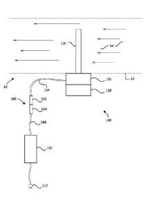
Date Recue/Date Received 2022-05-31
- 2 -
contaminates known to exist within heating, ventilation, and air conditioning
(HVAC)
systems." Col. 1, II. 15-17. The system disclosed in the '134 patent includes
a UV
lamp that is mounted to a base piece that can be inserted into a lateral side
of
ductwork to expose the air in the ductwork to the UV light emitted from the UV
lamp.
This system exposes the air moving through the ductwork to the UV light to
kill
bacteria and virus that may be present in the recirculated air.
[0005] One problem with the '134 patent is that the power connections for the
system are not sealed from the air in the ductwork. For example, the '134
patent
describes that a protrusion 50 on the base will interact with a switch in the
power
unit. However, there is no seal between the air duct and the switch. This will
unfortunately expose the switch and electrical components to corrosion and
moisture
that will cause the internal electronics to prematurely fail. For example,
with respect
to FIG. 4 the internal components of the fixture are completely exposed and
open to
the ductwork via channel 80.
[0oos] Another problem with the '134 patent is that it utilizes a spring
switch to
selectively switch the power to the UV lamp. For example, when the power unit
10 is
rotated, the protrusion 50 that interacts with switch 52 moves away from
switch 52
allowing the power to be cut off from the UV lamp. However, moisture from the
air in
the ductwork will severely corrode the spring switch causing a failure of the
switch to
turn off. This would result in person removing the UV lamp being directly
exposed to
the intense UV light, which is very dangerous.
[0007] Still another problem with the '134 patent is that there is a window
that is
provided in the base that provides a visual indication to someone looking
through the
window as to whether the UV lamp is currently functioning. However, UV light
is very
dangerous, especially at the intensity levels needed to kill viruses such as
Covid.
Additionally, there is no means of knowing whether the UV lamp is functioning
short
of physically entering the space and visually confirming that the UV is
exiting a
window provided in the base portion of the light.
Date Recue/Date Received 2022-05-31
- 3 -
[0oos] Accordingly, it would be advantageous to provide a UV light
disinfectant
system that could be removably mounted in a ductwork that would address the
problems described above.
SUMMARY OF THE INVENTION
[0oos] What is desired is a system and method for disinfecting air moving
through a
ductwork with UV light where the electronics for the UV light are protected
from the
adverse elements of the ductwork.
[0olo] It is further desired to provide a system and method for disinfecting
air
moving through a ductwork that provides enhanced safety by preventing a user
from
being contacted by the intense UV light when inspecting the system or changing
the
UV lamp.
[0011] It is still further desired to provide a system and method for
disinfecting air
moving through a ductwork that is reliable and is not subject to failure due
to
common wear of mechanical pieces.
[0012] It is yet further desired to provide a system and method for
disinfecting air
moving through a ductwork that can provide an indication to a user in a safe
manner
that the UV lamp has failed or should be replaced.
[0013] In one configuration, a system is provided that includes a base that is
connectable to an exterior surface of ductwork. The base portion includes a
central
opening that is designed to fit over an opening formed in the ductwork. The
base
further includes a power connector that is coupled to AC power for providing
electrical power to the UV lamp. The power connector is provided as a raised
power
socket affixed to the base that is designed to mate with a configuration of
pins.
[0014] The system further includes a removeable body that includes a UV lamp
socket adapted to receive the UV lamp. The removeable body includes a power
socket cavity that is designed to engage with and receive the raised power
socket on
the base. The power socket cavity is provided with several pins that are
designed to
engage with corresponding openings positioned in the raised electrical socket.
In
Date Recue/Date Received 2022-05-31
- 4 -
one configuration the power socket cavity is provided with at least one
undercut the
interacts with a corresponding undercut on the raised power socket such that
when
the raised power socket if is fulling inserted into the power socket cavity
the
undercuts interact to lock the removeable body and base together. In another
configuration the raised power socket is provided with one or more 0-rings
that
provide a moisture seal to ensure that no vapor or corrosive substance enters
the
socket to corrode the pins or connecters.
[0015] The UV lamp socket may also be provided with a raised wall that
surrounds
the UV lamp socket and has an outer diameter that corresponds to an inner
diameter
of the opening in the base. This wall functions as a light shield such that
when a user
is withdrawing the removeable body from the base, the raised wall will prevent
any
UV light from laterally escaping prior to the pins in the power cavity
disconnecting
from the raised power receptacle.
[0016]
[0017] Opposite the raised power receptable is a protrusion extending from the
base. The protrusion is designed to be received in a corresponding locking
cavity on
the removeable body. The lateral cavity is provided opposite the power socket
cavity.
The protrusion may be formed as two tines that are adapted to frictionally
interact
with the locking cavity providing further stabilization for the removeable
body.
[0ols] In still another configuration, the base is provided with a plurality
of openings
that may be formed in the periphery of the base around the central opening and
/ or
on laterally extending tabs that correspond to openings on the removeable
body.
These openings are provided to mount or secure the base to the ductwork. In
one
configuration, both the base and the removeable body may be secured to the
ductwork with screws or bolts. In another configuration only the base is
secured to
the ductwork with screws or bolts and the removable base is then secured to
the
base with screws or is only friction-fit secured to the base.
[0ols] In another configuration, the raised power socket is detachable from
the
base. For example, the base can be provided with a power socket opening that
is
Date Recue/Date Received 2022-05-31
- 5 -
designed to receive the raised power socket. The raised power socket may be
provided with deformable locking devices that interact with an inner upper
edge of
the power socket opening such that when the raised power socket is fully
inserted
into the power socket opening, the locking devices pass beyond the upper inner
edge of the power socket opening and prevent the raised power socket from
being
withdrawn from the power socket opening.
[0020] A power cord extends from the raised power socket to a ballast, which
in turn
has a cord extending therefrom to be connected to a source of AC (e.g., 120V
AC).
The ballast will convert and regulate the 120V AC to an appropriate voltage
and
frequency for use with commercial UV lamps used for disinfection.
[0021] It should be noted that the pin configuration for the UV lamp could
comprise
either a 2 or 4 pin configuration as is known in the art.
[0022] In still another configuration an over-limit thermostat is provided in
the power
cord / cable that is coupled to the raised power receptacle.
[0023] It is contemplated that the system may be provided with diagnostic
capabilities that can provide an alert if the UV lamp fails. For example, if
the UV lamp
fails and shuts off, the system could provide a visual indication of the
failure (e.g., a
Red LED that flashes). If the UV lamp is installed and functioning properly,
the
system could provide a positive indication (e.g., a Green LED). In this way a
simple
visual indication from the exterior of the ductwork can be done to confirm the
device
is functioning properly without any need of being exposed to the harmful UV
light.
[0024] In addition to the visual indication an audio warning could be provided
(e.g.,
a chip) to alert individuals that the UV lamp has failed. Since ductwork is
typically
located in closed rooms or spaces that see little traffic, it is further
contemplated that
an automatic warning could be transmitted that the UV lamp has failed or that
it
should be replaced. For example, with the advent of the Internet of Things
(loT), it is
possible to have a message sent as a text or email to for example, a user
device via
a network connection.
[0025] For this application the following terms and definitions shall apply:
Date Recue/Date Received 2022-05-31
- 6 -
[0026] The term "data" or "information" as used herein means any indicia,
signals,
marks, symbols, domains, symbol sets, representations, and any other physical
form
or forms representing information, whether permanent or temporary, whether
visible,
audible, acoustic, electric, magnetic, electromagnetic or otherwise
manifested. The
term "data" as used to represent predetermined information in one physical
form
shall be deemed to encompass any and all representations of the same
predetermined information in a different physical form or forms.
[0027] The term "network" as used herein includes both networks and
intemetworks
of all kinds, including the Internet, and is not limited to any particular
network or inter-
network.
[0028] The terms "first", "second" and "third" are used to distinguish one
element,
set, data, object or thing from another, and are not used to designate
relative
position or arrangement in time.
[0029] The terms "coupled", "coupled to", "coupled with", "connected",
"connected
to", and "connected with" as used herein each mean a relationship between or
among two or more devices, apparatus, files, programs, applications, media,
components, networks, systems, subsystems, and/or means, constituting any one
or
more of (a) a connection, whether direct or through one or more other devices,
apparatus, files, programs, applications, media, components, networks,
systems,
subsystems, or means, (b) a communications relationship, whether direct or
through
one or more other devices, apparatus, files, programs, applications, media,
components, networks, systems, subsystems, or means, and/or (c) a functional
relationship in which the operation of any one or more devices, apparatus,
files,
programs, applications, media, components, networks, systems, subsystems, or
means depends, in whole or in part, on the operation of any one or more others
thereof.
[0030] The term "automatic" and variations thereof, as used herein, refers to
any
process or operation done without material human input when the process or
operation is performed. However, a process or operation can be automatic, even
though performance of the process or operation uses material or immaterial
human
Date Recue/Date Received 2022-05-31
- 7 -
input, if the input is received before performance of the process or
operation. Human
input is deemed to be material if such input influences how the process or
operation
will be performed. Human input that consents to the performance of the process
or
operation is not deemed to be "material."
[0031] As used herein, the phrases "at least one," "one or more," "or," and
"and/or"
are open-ended expressions that are both conjunctive and disjunctive in
operation.
For example, each of the expressions "at least one of A, B and C," "at least
one of A,
B, or C," "one or more of A, B, and C," "one or more of A, B, or C," "A, B,
and/or C,"
and "A, B, or C" means A alone, B alone, C alone, A and B together, A and C
together, B and C together, or A, B and C together.
[0032] In one configuration, a system for disinfecting the air moving within a
ductwork is provided, the system comprises a base that is connectable to an
exterior
surface of the ductwork, the base including a central opening that is designed
to be
aligned with an opening formed in the surface of the ductwork and a power
connector formed as a raised power socket and coupled to a power cord. The
system further comprises a removable body including a UV lamp socket designed
to
receive a UV lamp and a power socket cavity including a plurality of pins
adapted to
engage with openings formed in the raised power socket where the UV lamp
socket
is electrically coupled to the plurality of pins. The system is provided such
that the
raised power socket includes a seal that is adapted to engage with an inner
surface
of the power socket cavity to seal the pins from moisture entering the power
socket
cavity.
[0033] In another configuration, a system for disinfecting the air moving
within a
ductwork is provided, the system comprises a base that is connectable to an
exterior
surface of the ductwork, the base including a central opening that is designed
to be
aligned with an opening formed in the surface of the ductwork, a power
connector
formed as a detachable raised power socket and coupled to a power cord, where
the
power cord includes an over-limit thermal switch formed in the power cord. The
system further comprises a removable body including a UV lamp socket designed
to
receive a UV lamp and a power socket cavity including a plurality of pins
adapted to
Date Recue/Date Received 2022-05-31
- 8 -
engage with openings formed in the raised power socket where the UV lamp
socket
is electrically coupled to the plurality of pins.
[0034] Other objects of the invention and its particular features and
advantages will
become more apparent from consideration of the following drawings.
BRIEF DESCRIPTION OF THE DRAWINGS
[0035] FIG. 1 is a diagram of the UV light system installed in the side of a
duct
according to one configuration of the invention.
[0036] FIG. 2 is an illustration of the removeable body according to FIG. I.
[0037] FIG. 3 is an illustration of the removeable body according to FIG. 2.
[0038] FIG. 4 is an illustration of the removeable body according to FIG. 2.
[0039] FIG. 5 an illustration of the base according to FIG. I.
[0040] FIG. 6 is an illustration of the base according to FIG. 5.
[0041] FIG. 7 is an illustration of the base according to FIG. 5.
[0042] FIG. 8 is an illustration of the removeable body being inserted into
the base
according to FIG. I.
[0043] FIG. 9 is the male side of an in-line thermal switch for a power cord
that is
coupled to a power receptacle that is removably coupled to the base according
to
FIG. I.
[0044] FIG. 10 is the female side of the in-line thermal switch according to
FIG. 1.
[0045] FIG. 11 is an illustration of the base with a dongle according to FIG.
1.
[0046] FIG. 12 is an illustration of the power receptacle and dongle according
to
FIG. 11.
[0047] FIG. 13 is an illustration of the UV light system assembled according
to FIG.
1.
Date Recue/Date Received 2022-05-31
- 9 -
DETAILED DESCRIPTION OF THE INVENTION
[0048] Referring now to the drawings, wherein like reference numerals
designate
corresponding structure throughout the views.
[0049] FIG. 1 is a diagram of the UV light disinfection system 100 installed
in an air
duct 10. The UV light disinfection system 100 includes a base 102 that is
affixed to
an exterior surface 12 of the duct. The base 102 includes a power cord 104
that is
coupled at a distal end to a thermal switch 106, which in turn is connected
via a
power cable 108 to a ballast 110. The ballast is then connectable to a power
source
via a plug-in connector 112. It should be noted that while a plug-in connector
112 is
illustrated, those of skill in the art will appreciate that a hard-wired
connection could
also be used depending on the voltage supplied to the ballast 110 (e.g., 120V,
277V,
etc.).
[0050] The thermal switch 106 as illustrated in FIG. 1 is formed as two
disconnectable units formed as a male and female connector 114, 116
respectively
and are shown in more detail in connection with FIGS. 9 and 10.
[0051] Also shown in FIG. 1 is removable body 118 that includes a UV lamp 120.
Power is supplied to the base 102, which is fed to the removable body 118 to
power
the UV lamp 120. The UV lamp 120 is positioned inside of the duct 10 and in
the flow
of air 14 within the duct 10. The UV light emitted from the UV lamp 120
functions to
kill virus and /or bacteria that may be resident in the circulating air.
[0052] Referring now to FIGS. 2-4, the removeable body 118 is shown in greater
detail. The removeable body 118 is provided with a power socket cavity 122
that
include one or more (in this case four) power pins 124 that are designed to
engage
with a corresponding receptacle on the base 102. The power pins are adapted to
transmit electrical power from the power pins 124 to corresponding UV socket
receptacle 126 positioned in UV cavity 128. In this configuration, four power
pins 124
are provided. However, one of skill in the art will understand that any number
of pins
may be provided (i.e., 2-pin, 4-pin) and that more than one UV socket
receptacle
may be provided.
Date Recue/Date Received 2022-05-31
- 10 -
[0053] The UV cavity 128 is bounded by a raised wall 130 that extends upward
from
a face of the UV socket receptacle 126. The raised wall 130 functions as a
light
shield when the removable body is being withdrawn from or inserted into the
base
102. This function will be described in greater detail in connection with FIG.
8.
[0054] The removeable body 118 further includes a lateral cavity 132
positioned
opposite the power socket cavity 122 from the raised wall 130. Lateral cavity
132 is
adapted to interact with a protrusion 164 (FIG. 5) positioned on base 102.
[0055] Also illustrated are laterally extending tabs 134, 134' which include
lateral
openings 136, 136' respectively that are adapted to receive a bolt or a screw
170,
170' (FIG. 8) for securing the removable body 118 to the base 102.
[0056] An upper portion 138 of the removable body 118 is provided with a
gripping
surface 140 formed as a raised portion allowing a user to firmly grasp the
removable
body 118 when detaching it from the base 102.
[0057] Turning now to FIGS. 5-7, the base 102 is illustrated from several
different
angles. In particular, the base 102 is provided with a central opening 142,
which is
designed to align with a hole that is cut into the side of a duct. The base
includes two
laterally extending tabs 144, 144' that are generally aligned with the
laterally
extending tabs 134, 134' on the removable body 118. Lateral openings 146, 146'
are
provided in laterally extending tabs 144, 144' respectively. In this way, when
the
removable body 118 is positioned on base 102, it can be secured by screws or
bolts
170, 170' (FIG. 8) extending through the lateral openings 136, 136', 146,
146'.
Additional openings 148, 148' may also be provided in base 102.
[0058] Also shown in base 102 is raised power receptacle 150. Raised power
receptacle 150 is provided as a removeable power device that is secured in
power
receptacle opening 190, which is better seen in FIG. 11. The raised power
receptacle 150 is provided with at least one tine 152 that is provided with an
undercut 154 adapted to interact with an edge 156 of the power receptacle
opening
190. To form an interlock between the tine 152 and the edge 156. To remove the
raised power receptacle 150, the tine 152 must be pushed inward relative to
the
Date Recue/Date Received 2022-05-31
-11 -
edge 156, such that the raised power receptacle 150 can be pushed downward
relative to the edge 156 and withdrawn from power receptacle opening 190.
[0059] The raised power receptacle 150 is provided with at least one seal 158
positioned on an exterior surface thereof. While two seals 158 are illustrated
in FIGS.
5-7, it is contemplated that one or more than two may be provided. The seal
158 is
designed in interact with an inner surface of power socket cavity 122 to form
a seal
preventing moisture from reaching pins 124 and power sockets 160 that are
adapted
to receive pins 124 respectively. The seal 158 can be formed of any suitable
material
that can form a moisture seal such as silicon or rubber. The seal 158 will
typically sit
in a channel 162 that is cut into the surface of the raised power receptacle
150 to
securely hold the seal 158 in place.
[0ow] Also shown in FIGS. 5-7 is a protrusion 164 that is formed as two
parallel
extending protrusions. The protrusion 164 is formed to match the interior
surface of
lateral cavity 132. For example, an exterior surface of protrusion 164 is
partially
formed as a rounded surface where a distal end 166 of protrusion 164 may be
provided with beveled edge. It is contemplated that the protrusion will
friction fit
within lateral cavity 132.
[0061] FIG. 8 provides an exploded view of the base 102 and removable body
118.
As can be seen, bolts or screws 170, 170' may be used to secure the removable
body 118 to base 102. It is contemplated that these maybe secured through the
duct
12 or the base 102 may be independently secured to the duct 12 and the
removable
body 118 is then secured to base 102.
[0062] In operation, the UV lamp that is attached to removable body 118 will
not be
turned on until the power pins 124 make electrical contact with power sockets
160.
The device is designed such that the power pins 124 not make electrical
contact with
power sockets 160 until the removable body 118 is seated well down onto base
102.
This allows the upstanding wall 130 to enter the central opening 142 prior to
the UV
lamp 120 turning on thereby forming a light shield to prevent UV light from
impinging
on any worker installing or maintaining the system 100.
Date Recue/Date Received 2022-05-31
- 12 -
[0063] Additionally, the power pins 124 are inserted in each of their
respective
power sockets 160 some distance prior to electrical contact being made. This
ensure
that no arching can occur between pins to or to any other part of the device.
A major
problem that has been noted with duct-mounted UV light disinfectant systems is
that
moisture can build up in the light and especially around the power coupling.
This
moisture functions to corrode the pins and lowers the resistance for arching
within
the light fixture. The carbon scoring and subsequent damage to the UV light
fixture
require complete removal and replacement of the light fixture well before the
lifespan
of the device has been reached. However, the unique design of the UV light
disinfectant system 100 addresses many of these problems by providing the
raised
power receptable 150 that interacts with power cavity 122. Additionally, the
seals
158 on the surface of the raised power receptable 150 interacts with the inner
surface of the power cavity 122 to prevent moisture from reaching the power
pins
124 and the respective power sockets 160. Finally, the configuration of the
power
sockets 160 not allowing connection to the power pins 124 until the power pins
124
are almost fully inserted also prevents arching and ensures power is not
turned on to
the UV lamp until the upstanding wall enters central opening 142. All these
features
greatly enhance the safety and reliability of the UV light disinfectant system
100.
[0064] FIGS. 9 and 10 show the male connector 114 and female connector 116
that
form thermal switch 106 that is formed in-line with power cord 104 and power
cable
108 respectively. Male connector 114 includes a body 172 that includes a
locking
mechanism 174 in the form of a laterally displaceable arm. The female
connector
also includes a body 176 having a protrusion 178 that is adapted to interact
with
locking mechanism 174 when the two are axially aligned and inserted.
[0065] The male connector is formed have four pins 180, 180', 180", 180¨ that
may
be formed in four axially extending structures 182, 182', 182", 182", which in
this
case are formed as rectangular structures. The axially extending structures
182,
182', 182", 182¨ are integrally formed as part of the body 172 providing
lateral
strength and protection to the pins 180, 180', 180", 180¨ to avoid damage. The
end
197 of the body 172 may be provided with a seal 198 that overlays the end 197.
Date Recue/Date Received 2022-05-31
- 13 -
pow The female connector 116 is provided with four receptacles 184, 184',
184",
184" that are designed to receive the axially extending structures 182, 182',
182",
182" and allow for the pins 180, 180', 180", 180" to form an electrical
connection to
the four wires extending through the power cord 106 to raised power receptacle
150.
[0067] When the end 199 abuts end 197, the seal 198 forms a moisture tight
seal
therebetween preventing any moisture from getting into the pins 180, 180',
180",
180" causing corrosion or arching. It is contemplated that the seal may
comprise
any type of material that is pliable a liquid resistant as is known in the
art.
Additionally, the seal 198 not only surrounds the perimeter of end 197, but in
one
embodiment covers the entire face of end 198 including the areas of the face
197 in
between the axially extending structures 182, 182', 182", 182". In this
manner, not
only are the pins 180, 180', 180", 180" sealed from the outside, but are
sealed from
each other.
pow FIGS. 11-12 illustrate the removeable nature of the raised power
receptacle
150 from the base 102. For example, as can be seen in FIG. 11, the raised
power
receptacle, the power cord 104 and the female connector 116 (collectively, a
detachable power dongle 188) is shown fully inserted into base 102. FIG. 12
shows
the detachable power dongle 188 completely detached from base 102. To attach
the
detachable power dongle 188 to base 102, the raised power receptacle is simply
inserted into power receptacle opening 190. As tine 152 enters power
receptacle
opening 190 as raised power receptacle 150 is advanced, this will function to
laterally displace tine 152 inward. Once tine 152 passes edge 156 it will snap
outward again forming an interlock preventing the raised power receptacle from
being removed from power receptacle opening 190. It is contemplated that while
a
mechanical interlock is illustrated, different types of interlocks could be
provided
including, for example, a friction fit, or a groove and channel configuration
and the
like.
pow FIG. 13 is a view of the removable body 188 affixed to the base 102,
which is
in turn affixed to a mounting plate 192 that may be affixed to the outer
surface of the
duct 12. The mounting plate may be affixed to the duct via screws or bolt via
holes
Date Recue/Date Received 2022-05-31
- 14 -
194. The mounting plate may comprise metal or any other appropriate material.
Also
shown are the male and female connectors 114, 116 attached to power cable 108
and power cord 106 respectively.
[0070] Also shown in FIG. 13 is an indicator 196 that may be positioned on or
in
removable body 118. In one configuration, the indicator 196 may be provided as
one
or more LEDs that provide a visual status indication of the UV lamp 120.
[0071] It is contemplated that the UV light disinfectant system 100 may be
provided
with the ability to run self-diagnostics to determine the status of the UV
lamp 120. In
one configuration, if the UV lamp burns out or does not turn on (i.e., the
ballast 110
is not functioning properly), the UV light disinfectant system 100 could
provide an
indication of the failure. In one configuration, the indictor 196 could
provide a flashing
red LED as opposed to showing a solid green LED when functioning properly.
This is
a simple and easy way to provide UV lamp 120 function information for
maintenance
personnel that are performing an inspection of the device.
[0072] It is further contemplated that the indicator 196 may provide an audio
indication to alert maintenance personnel of a UV lamp 120 failure. The audio
indication could be provided as a chip as is common with, for example, smoke
detectors.
[0073] As ducts are often located in closed rooms or spaces that see little
traffic, it
may further be advantageous to provide a remote indication. For example, if
the UV
lamp disinfectant system 100 determines that the UV lamp 120 is out or the
system
is malfunctioning, an automatic warming could be transmitted via a network
connection to a remote computer. This automatic warning could be transmitted
wirelessly to a building automation system computer providing information
relating to
the location of the device in the facility. The building automation system
could then
automatically transmit information relating to the warning to a mobile device
carried
by maintenance personnel in the form of a text message or email, or even
automatically generate a work order to service the device. Alternatively, it
could be
that the UV lamp disinfection system 100 has measured the total operating
hours of
the UV lamp 120 and sends an indication that the UV lamp is nearing the end of
its
Date Recue/Date Received 2022-05-31
- 15 -
life and thus, should be replaced. All of these are possible integration of
the device
via loT to provide automated indication, whether to a remote computer in a
facility, or
even a message sent to a user's mobile phone for installations in private
homes.
[0074] Although the invention has been described with reference to a
particular
arrangement of parts, features and the like, these are not intended to exhaust
all
possible arrangements or features, and indeed many other modifications and
variations will be ascertainable to those of skill in the art.
Date Recue/Date Received 2022-05-31