Note: Descriptions are shown in the official language in which they were submitted.
CA 03161567 2022-05-12
WO 2021/101869 PCT/US2020/060850
DETECTING ELECTRICAL ARCING IN HOUSEHOLD ELECTRICAL WIRING
CROSS-REFERENCE TO RELATED APPLICATIONS
paw This application claims benefit of United States patent
application serial
number 16/688,989 filed November 19, 2019, which is hereby incorporated herein
by
reference.
BACKGROUND
Field of the Various Embodiments
[0002] The various embodiments relate generally to residential
electrical systems
and, more specifically, to detecting electrical arcing in household electrical
wiring.
Description of the Related Art
[0003] Electrical failures or malfunctions resulting from electrical
arcing are a
leading cause of fires in households and other building structures. Electrical
arcing is
characterized by an electric arc that produces a prolonged electrical
discharge. There
are several types of electrical arcing. Parallel arcing occurs when the line
wire is
shorted to the neutral wire and can occur when the insulating medium
surrounding
electrical wiring breaks down. Parallel arcing typically trips a circuit
breaker, which
cuts off electricity to the circuit where the parallel arcing occurred.
Similarly, ground
arcing occurs when the line wire is shorted to the ground wire, which
typically trips a
ground fault circuit interrupter (GFC I). Series arcing occurs in series with
a load and
can occur when wired or plugged connections to an electrical outlet
deteriorate over
time. Series arcing can be more difficult to detect than parallel or ground
arcing and
often does not trip a circuit breaker. As a result, series arcing may occur
over an
extended period of time without being detected. The high temperatures normally
associated with electrical arcing can cause related electrical fires that, in
turn, can
result in significant property damage and personal injury or death.
[0004] In order to prevent fires caused by electrical arcing, certain
electrical codes,
such as the National Electrical Code (NEC), require arc fault circuit
interrupters
(AFCIs) to be installed on certain branch circuits in residential households.
Most
AFC's are designed as circuit breakers that can be installed in an electrical
panel
within a household. Each such AFCI-type circuit breaker is designed to protect
one or
more electrical household components serviced by the branch circuit connected
to the
AFCI-type circuit breaker. When an AFCI-type circuit breaker detects an
electric arc
1
CA 03161567 2022-05-12
WO 2021/101869 PCT/US2020/060850
in the branch circuit to which the circuit breaker is connected, the circuit
breaker trips,
thereby reducing the likelihood that the electric arc is able to generate a
temperature
high enough to start a fire.
[0005] One drawback with AFC I-type circuit breakers is that each such
circuit
breaker is designed to protect only one branch circuit. Further, AFC I-type
circuit
breakers are typically more expensive than standard circuit breakers. In order
to save
costs, a homeowner typically chooses to install AFCI-type circuit breakers
only on
those specific branch circuits for which electrical regulations require AFCI-
type circuit
breakers and to install standard circuit breakers on the remaining branch
circuits
within the household. Consequently, electrical arcs are detectable only on a
subset of
branch circuits within the household. In addition, older households that were
built
prior to the electrical regulations requiring AFCI-type breakers typically
have no AFCI-
type circuit breakers at all.
[0006] Another drawback with AFC I-type circuit breakers is that such
circuit
breakers are usually designed to detect only certain types of electrical arcs.
For
example, in order to avoid false triggers, some AFCI-type circuit breakers are
typically
designed to detect only sudden, high-magnitude electrical arcing. However,
certain
electrical arcing conditions develop slowly over time, such as when wire
insulation or
the electrical components within an electrical outlet deteriorate over time.
Generally
speaking, AFC I-type circuit breakers are not designed to detect these more
gradual
electrical arcing conditions. Accordingly, certain types of electrical arcing
can cause
electrical fires, even on branch circuits that are protected with AFC I-type
circuit
breakers.
[0007] As the foregoing illustrates, what is needed in the art are more
effective
ways of detecting electrical arcing in electrical wiring.
SUMMARY
[0oos] Various embodiments include a computer-implemented method for
detecting electrical arcing in an electrical system. The method includes
acquiring, via
a first power line communications (PLC) modem, first voltage readings
associated
with an electrical circuit, where the first voltage readings include high-
frequency
components associated with a line voltage. The method further includes
performing
one or more operations based on the first waveform data to determine that an
2
CA 03161567 2022-05-12
WO 2021/101869 PCT/US2020/060850
electrical arcing condition is present within the electrical circuit. The
method further
includes performing a remedial operation in response to determining that the
electrical
arcing condition is present.
[0009] Other embodiments include, without limitation, one or more non-
transitory
computer-readable media storing instructions for performing one or more
aspects of
the disclosed techniques, as well as a system for performing one or more
aspects of
the disclosed techniques.
[0olo] At least one technical advantage of the disclosed techniques
relative to the
prior art is that electrical arcing can be detected for an entire site, such
as a
household or other building structure, from a single location. Thus, with the
disclosed
techniques, a residence or other building structure can be protected from
electrical
arcing without having to replace all circuit breakers within the structure
with AFCI-type
circuit breakers. Another technical advantage relative to the prior art is
that, with the
disclosed techniques, is that, by analyzing a frequency spectrum derived from
voltage
readings over sequential time periods, electrical arcing conditions that
develop slowly
over time can be detected. By contrast, conventional current-based arc-fault
circuit
interrupters only detect only sudden, high-magnitude electrical arcing and are
unable
to analyze such long-term electrical arcing conditions. These technical
advantages
represent one or more technological advancements over prior art approaches.
BRIEF DESCRIPTION OF THE DRAWINGS
[0011] So that the manner in which the above recited features of the
various
embodiments can be understood in detail, a more particular description of the
inventive concepts, briefly summarized above, may be had by reference to
various
embodiments, some of which are illustrated in the appended drawings. It is to
be
noted, however, that the appended drawings illustrate only typical embodiments
of the
inventive concepts and are therefore not to be considered limiting of scope in
any
way, and that there are other equally effective embodiments.
[0012] Figure 1 illustrates a system configured to implement one or more
aspects
of the various embodiments;
[0013] Figure 2 illustrates a more detailed view of one of the sites of
Figure 1,
according to various embodiments;
3
CA 03161567 2022-05-12
WO 2021/101869 PCT/US2020/060850
[0014] Figure 3 illustrates a more detailed view of the network
communications
device of Figure 1, according to various embodiments;
[0015] Figure 4 illustrates a more detailed view of the network
communications
device of Figure 1, according to various other embodiments;
[0016] Figures 5A-5C illustrate various types of electrical arcing
conditions that
can occur in the circuit of Figure 2, according to various embodiments;
[0017] Figures 6A-6D illustrate waveforms characteristic of the
electrical arcing
conditions that can occur in one of the electrical circuits of Figure 2,
according to
various embodiments; and
lo [0018] Figure 7 is a flow diagram of method steps for detecting
electrical arcing in
an electrical system, according to various embodiments.
DETAILED DESCRIPTION
[0019] In the following description, numerous specific details are set
forth to
provide a more thorough understanding of the various embodiments. However, it
will
be apparent to one of skilled in the art that the inventive concepts may be
practiced
without one or more of these specific details.
[0020] As further described herein, a site, such as a residential
household or other
structure, includes one or more network communications devices, typically in
the form
of an electrical meter. In general, a residential household includes a single
network
communications device. However, any given site may include any technically
feasible
number of network communications devices, within the scope of the disclosed
embodiments. Network communications devices communicate with one another via
power line communications (PLC). PLC enables the network communications device
to perform outbound communications to edge devices and to network
communications devices at other sites over the power lines of the electrical
system.
Typically, PLC circuitry included in the electrical meter or other network
communications device is the sole PLC-capable device in a residential
household. As
further described herein, the network communications device employs the PLC
circuitry to continuously monitor and analyze, as a background process, one or
more
.. circuits in order to detect electrical arcing. The PLC circuitry detects
electrical arcing
conditions for the entire site from a single location via analysis of voltage
4
CA 03161567 2022-05-12
WO 2021/101869 PCT/US2020/060850
measurements taken at the network communications device.
System Overview
[0021] Figure 1 illustrates a system 100 configured to implement one or
more
aspects of the various embodiments. As shown, the system 100 includes a
plurality
.. of network communications devices 102(1), 102(2) . . . 102(M) a plurality
of sites
104(1), 104(2) . . . 104(N), a central office 106, and an edge device 108.
Central
office 106 communicates with edge device 108 via a network 110. Network
communications devices 102(1), 102(2) . . . 102(M) communication with the edge
device 108 and with other network communications devices 102(1), 102(2) . . .
102(M) via PLC and/or radio frequency (RF) communications. Edge device 108
communicates with network communications devices 102(1), 102(2) . . . 102(M)
via a
utility communication network 112. Each of the network 110 and the utility
communication network 112 includes any technically feasible combination of a
wide
area network (WAN), metropolitan area network (MAN), local area network (LAN),
neighborhood area network (NAN), personal area network (PAN), or the like.
[0022] The plurality of network communications devices 102(1), 102(2) .
. . 102(M)
(collectively referred to as network communications devices 102) is associated
with a
plurality of sites 104(1), 104(2) . . . 104(N) (collectively referred to as
sites 104). M
represents a number of network communications devices 102 in the utility
.. communication network 112, where M is any integer greater than 0. N
represents a
number of individual sites 104 serviced by network communications devices 102
in
the utility communication network 112, where N is any integer greater than 0.
The
number M of network communications devices 102 may or may not be equal to the
number N of sites 104, because since some sites 104 may include multiple
network
communications devices 102. Additionally or alternatively, some network
communications devices 102 may serve multiple sites 104. The network
communications devices 102 communicate with one another via PLC and/or RF
communications. PLC enables each of the network communications devices 102 to
perform outbound communications over the power lines of the electrical system.
As
further described herein, each of the network communications devices 102
employs
the PLC circuitry to continuously monitor and analyze, as a background
process, one
or more circuits in order to detect electrical arcing. The PLC circuitry
detects
electrical arcing conditions for the entire site from a single location via
analysis of
5
CA 03161567 2022-05-12
WO 2021/101869 PCT/US2020/060850
voltage measurements taken at the network communications device 102.
[0023] The network communications devices 102 are configured as, or in
connection with, a variety of other computing devices including, without
limitation,
electricity meters, smart utility meters (e.g., electric, gas, and water
meters), sensors
(e.d., temperature sensors, weather stations, and frequency sensors, etc.),
control
devices, transformers, switches. The system 100 represents a heterogeneous
network of network communications devices 102. In that regard, the system 100
includes any technically feasible combination of different types of network
communications devices 102 (e.g., smart meters, cellular relays, sensors,
etc.).
Additionally or alternatively, the system 100 includes any technically
feasible
combination of different generations or models of network communications
devices
102. Additionally or alternatively, the system 100 includes any technically
feasible
combination of network communications devices 102 that are capable of
transmitting
on different channels and using different modulation techniques, data rates,
protocols,
signal strengths, and/or power levels.
[0024] The network communications devices 102 are configured to
communicate
with a central office 106 via an edge device 108 that serves as a connection
point to
one or more backhaul networks 110, such as the Internet. The edge device 108
includes any one or more of a data collector, a cellular relay, a cellular
router, an edge
router, and a destination oriented directed acyclic graph (DODAG) root.
[0025] The utility communication network 112 is configurable as a "star
network" in
which the network communications devices 102 communicate directly with the
edge
device 108 (as shown). Additionally or alternatively, the utility
communication network
112 is configurable as a "mesh network" in which the network communications
devices 102 communicate with the edge device 108 either directly or via one or
more
intervening upstream devices (not shown). In this regard, the architecture of
the
system 100 of Figure 1 is generically representative of either a star network
or a mesh
network.
[0026] Figure 2 illustrates a more detailed view of one of the sites 104
of Figure 1,
according to various embodiments. As shown, a network communications device
102
receives line 1 voltage 210, line 2 voltage 212, and neutral 214. Line 1
voltage 210,
line 2 voltage 212, and neutral 214 may be any technically feasible voltage
level. In
6
CA 03161567 2022-05-12
WO 2021/101869 PCT/US2020/060850
some embodiments, the voltage difference between line 1 voltage 210 and line 2
voltage 212 may be in the range of 220 V to 240 V. In such embodiments, the
difference between neutral and either line 1 voltage 210 or line 2 voltage 212
may be
110 V to 120 V. The network communications device 102 couples line 1 voltage
210,
line 2 voltage 212, and neutral 214 to a circuit breaker panel 202. The
circuit breaker
panel 202 may include any technically feasible number of circuit breakers
206(1),
206(2) ... 206(P), such as 10 circuit breakers, 20 circuit breakers, 50
circuit breakers,
or more, depending on the size and complexity of the site 104. Each circuit
breaker
206(1), 206(2) ... 206(P) is coupled to a corresponding electrical circuit
200(1), 200(2)
... 200(P). As shown, each electrical circuit 200(1), 200(2) ... 200(P) is
coupled with
and supplies electricity to one or more appliances 204(1), 204(2) . . .
204(P). The
appliances 204 are representative of any devices that are plugged in, directly
wired in,
or otherwise coupled to the electrical circuit 200. Appliances can include,
without
limitation, kitchen appliances, lamps, space heaters, and vacuum cleaners.
Typically,
the circuit breaker panel 202 and the electrical circuits 200(1), 200(2) ...
200(P) also
have a connection to safety ground, however, the safety ground connection is
not
shown in Figure 2 for the sake of clarity. In some cases, some appliance may
be
connected between two lines rather than between a single line and ground,
however,
this is not shown in Figure 2 for the sake of clarity.
[0027] As further described herein, the network communications device 102
includes communication technologies, such as power line communications (PLC).
Via PLC, the network communications device 102 transmits messages to and
receives messages from the edge device 108 and/or other network communications
devices 102 connected to the edge device 108. As further described herein, the
network communications device 102 employs the PLC communications circuitry to
continuously monitor and analyze voltage measurements over time in order to
detect
electrical arcing for an entire site 104 from a single location. In parallel,
the network
communications device 102 deploys the PLC components to analyze voltage
waveforms for electrical arcing detection. The network communications device
102
detects electrical arcing conditions between line 1 voltage 210 and line 2
voltage 212.
Additionally or alternatively, the network communications device 102 detects
electrical
arcing conditions between neutral and either line 1 voltage 210 or line 2
voltage 212.
7
CA 03161567 2022-05-12
WO 2021/101869 PCT/US2020/060850
Detecting Electrical Arcing in an Electrical System
[0028] Figure 3 illustrates a more detailed view of the network
communications
device of 102 Figure 1, according to various embodiments. As shown, the
network
communications device 102 includes, without limitation, a processor 302,
storage
304, an input/output (I/O) device interface 306, a communications module 308,
an
interconnect 310, and a system memory 312. The network communications device
102 further includes, without limitation, metrology sensors 356 and a PLC
module
368.
[0029] In general, processor 302 retrieves and executes programming
instructions
stored in system memory 312. Typically, processor 302 includes one or more
digital
signal processor (DSPs). More generally, processor 302 may be any technically
feasible form of processing device configured to process data and execute
program
code. Processor 302 could be, for example, a central processing unit (CPU), a
digital
signal processor (DSP), a graphics processing unit (GPU), an application-
specific
integrated circuit (ASIC), a field-programmable gate array (FPGA), and so
forth.
Processor 302 stores and retrieves application data residing in the system
memory
312. Processor 302 is included to be representative of a single processor,
multiple
processors, a single processor having multiple processing cores, and the like.
In
operation, processor 302 is the master processor of network communications
device
102, controlling and coordinating operations of other system components.
System
memory 312 stores software applications and data for use by processor 302.
Processor 302 executes software applications, also referred to herein as
software
application programs, stored within system memory 312 and optionally an
operating
system. In particular, processor 302 executes software and then performs one
or
more of the functions and operations set forth in the present application.
[0030] The storage 304 may be a disk drive storage device. Although
shown as a
single unit, the storage 304 may be a combination of fixed and/or removable
storage
devices, such as fixed disc drives, floppy disc drives, tape drives, removable
memory
cards, or optical storage, network attached storage (NAS), or a storage area-
network
(SAN). In some embodiments, the network communications device 102 may not
include storage 304. In such embodiments, processor 302 stores data in and
retrieve
data from dynamic random access memory (DRAM), flash memory, and the like.
Processor 302 communicates to other computing devices and systems via
8
CA 03161567 2022-05-12
WO 2021/101869 PCT/US2020/060850
communications module 308. The communications module 308 is configured to
transmit and receive data via a communications network, such as network 110,
via
the edge device 108 and/or one or more other network communications devices
102.
[0031] The communication module 308 may include hardware and/or software
components to enable one or multiple different modes of communication.
Software
components included in the communications module 308 may include, without
limitation, a software defined radio, drivers, libraries, applications, and
plugins. These
software components are stored in system memory 312 and executable or
accessible
by the processor 302. Additionally, in some embodiments, the communication
module 308 may include one or more of dedicated processors and/or memory.
[0032] In some embodiments, the communication module 308 may include an
RF
transceiver configured to transmit and/or receive RF signals via one or more
channels
or frequencies. The transceiver may include an RF front end and a baseband
processor or a software defined radio. In some implementations, each of the
network
communications devices 102 includes a single radio configured to send and
receive
data on multiple different channels, such as a control channel and multiple
data
channels of each communication link. The RF transceiver may also be configured
to
implement a plurality of different modulation techniques, data rates,
protocols, signal
strengths, and/or power levels. Additionally or alternatively, the
communication
module 308 includes a cellular or wide area network (WAN) module, or other
communication software and/or hardware to facilitate communication with other
devices in the utility communication network 112.
[0033] The interconnect 310 facilitates transmission, such as of
programming
instructions and application data, between the processor 302, input/output
(I/O)
devices interface 306, storage 304, communications module 308, system memory
312, metrology sensors 356, and PLC module 368. The I/O devices interface 306
is
configured to receive input data from user I/O devices 322. Examples of user
I/O
devices 322 may include one of more buttons, a keyboard, and a mouse or other
pointing device. The I/O devices interface 306 may also include an audio
output unit
.. configured to generate an electrical audio output signal, and user I/O
devices 322
may further include a speaker configured to generate an acoustic output in
response
to the electrical audio output signal. Another example of a user I/O device
322 is a
display device that generally represents any technically feasible means for
generating
9
CA 03161567 2022-05-12
WO 2021/101869 PCT/US2020/060850
an image for display. For example, the display device may be a liquid crystal
display
(LCD) display, CRT display, or DLP display. The display device may be a TV
that
includes a broadcast or cable tuner for receiving digital or analog television
signals.
[0034] The system memory 312 includes, without limitation, a metrology
-- application 358, a PLC application 364, and a data store 340. In operation,
processor
302 executes the metrology application 358 and the PLC application 364 to
perform
one or more of the techniques disclosed herein. Data store 340 may include
various
data structures retrieved by and/or stored by the metrology application 358
and the
PLC application 364.
[0035] In operation, the metrology application 358 executing on the network
communications device 102, and in conjunction with metrology sensors 356,
senses
and measures electricity consumption at the site 104. The metrology sensors
356 are
representative of any of a variety of hardware and/or software usable to sense
and
measure electricity consumption data of the site 104.
[0036] In operation, the PLC application 364 executing on the network
communications device 102, and in conjunction with the PLC module 368, enables
the network communications device 102 to communicate via PLC. In this regard,
the
PLC application 364 and the PLC module 368 form a PLC transceiver. The PLC
application 364 and the PLC module 368 are configured for communication with
other
-- network communications devices 102 and/or the edge device 108 in the
utility
communication network 112. At any given time, the PLC application 364 and PLC
module 368 are in one of three states: (1) transmitting PLC message packets;
(2)
receiving and decoding PLC message packets; and (3) waiting for PLC message
packets. The PLC application 364 and PLC module 368 spend the largest
percentage of time in the third state, waiting for PLC message packets. During
this
state, the PLC application 364 and PLC module 368 are able to analyze circuits
at the
site 104 in order to detect electrical arcing in parallel with waiting for PLC
message
packets. The PLC application 364 and PLC module 368 detect electrical arcing
conditions for the entire site from a single location via analysis of voltage
measurements taken at the network communications device 102.
[0037] The PLC module 368 includes a PLC coupler 360 to connect the PLC
module 368 to the electricity lines for communication. The PLC application
364, when
CA 03161567 2022-05-12
WO 2021/101869 PCT/US2020/060850
executing, interprets communications received by a PLC modem 366 and transmits
outgoing communications via the PLC modem 366. The PLC modem 366 acts at the
direction of the PLC application 364 to transmit and receive PLC
communications
over the circuit internal to the site 104. In some embodiments, the PLC modem
366
-- transmits and receives PLC communications over low, medium, and/or high-
voltage
power lines of the utility distribution network.
[0038] Messages transmitted via PLC include any technically feasible
information,
including, without limitation, a request to disconnect electricity service to
the site, an
alert of a potentially unsafe condition at the site, or a status notification.
Based on the
-- message, the network communications device 102 performs some action, such
as
connecting electricity service to the site 104 or relaying the alert.
[0039] The PLC application 364 engages the PLC module 368 to
continuously
monitor and analyze circuits at the site 104 in order to detect electrical
arcing. The
PLC application 364 performs this analysis over multiple power cycles. The PLC
-- application 364 acquires voltage waveform data and performs electrical
arcing
detection over multiple power cycles. The duration for each power cycle is 20
ms for
50 Hz power systems and 16.67 ms for 60 Hz systems. Based on these durations,
the PLC application 364 performs electrical arcing detection over a period of
80 ¨ 120
ms for 50 Hz power systems. Similarly, the PLC application 364 performs
electrical
-- arcing detection over a period of 66.67 ¨ 100 ms for 60 Hz power systems.
[0040] More specifically, the PLC application 364 analyzes circuits at
the site 104
via the PLC modem 366 in the PLC module 368. When in communications mode, the
PLC modem 366 is performing analog-to-digital conversion (ADC) and
demodulating
signal data present on the power line, and analyzing this signal data for an
expected
-- preamble which signifies the beginning of a message. In electrical arc
detection
mode, the PLC application 364 and the PLC modem 366 utilize the same ADC to
acquire voltage waveform data. The PLC application 364 and the PLC modem 366
detect abnormal spectral pattern on the voltage waveform data. The PLC
application
364 analyzes the mains voltage waveform data for anomalies and specific noise
-- patterns, which indicate a possible electrical arcing condition.
[0041] PLC communications typically involve modulation energy in the 1
kHz to 1
MHz range. In some embodiments, the PLC communications system operates in the
11
CA 03161567 2022-05-12
WO 2021/101869 PCT/US2020/060850
100 kHz to 500 kHz range. Consequently, when the PLC application 364 is
performing electrical arcing detection, the PLC application 364 is able to
detect
electrical arcing that exhibits signal energy in the 1 kHz to 1 MHz range or,
alternatively, in the 100 kHz to 500 kHz range. As further discussed herein,
this
range is consistent with the frequency range exhibited by typical electrical
arcing
conditions. In addition, the sensitivity of the receiver in the PLC module 368
is in the
range of 20 ¨ 50uV, which is sufficient for sensing even weak remote
electrical arcing
events.
[0042] During the analysis, the PLC application 364 records the voltage
waveform
data during the power cycles currently being analyzed. The PLC application 364
correlates and compares these voltage waveform data over an extended period of
time to look for trends indicating that an electrical arcing condition is
developing in
one or more circuits. Depending on the amount of available system memory 312,
the
PLC application 364 analyzes voltage waveform data over a period of weeks,
months,
or even years. Such long term analysis enables the PLC application 364 to
detect
long term growth and development of electrical arcing conditions on all
circuits at the
site 104.
[0043] In some embodiments, certain loads, such as space heaters,
refrigerators,
washing machines and dryers, electric ranges, air conditioning units, and
computers
all have unique and distinct load patterns that may be referred to as
signatures. The
PLC application 364 may correlate the amount of current drawn, the change in
current
draw over time, the time of day, and other data in order to generate these
signatures.
In this manner, the PLC application 364 may identify which loads are operating
at any
given time. The PLC application 364 may correlate this information with data
resulting from electrical arcing analysis in order to identify which load(s)
may be
associated with an electrical arcing condition.
[0044] Upon detecting an electrical arcing condition on an electrical
circuit, the
PLC application 364 performs one or more remedial operations. In one example,
the
PLC application 364 could disconnect the electrical circuits within the site
104 from
the electrical utility via a service disconnect (not shown), thereby
disconnecting power
from the site 104. In another example, the PLC application 364 could transmit
data
regarding the electrical arc via an edge device 108 to the central office 106
for
analysis. The data could include a sample of the voltage waveform data and/or
other
12
CA 03161567 2022-05-12
WO 2021/101869 PCT/US2020/060850
relevant data. In yet another example, the PLC application 364 could transmit
a
message to the central office 106 via an edge device 108. The message could
include an alert to notify the central office 106 that the electrical arcing
condition has
been detected. The central office 106 could subsequently transmit a request
for
further information to the PLC application 364 via the network communications
device
102. In response, the PLC application 364 could transmit additional data
regarding
the electrical arcing condition, such as a sample of the voltage waveform
data, to the
central office 106 for analysis. In yet another example, the PLC application
364 could
transmit such data and/or an alert to other nearby network communications
devices
102.
[0045] As described herein, the PLC application 364 in conjunction with
the PLC
modem 366 senses voltage but typically does not sense current. However, in
some
embodiments, the PLC application 364 may receive current waveform data in
addition
to the voltage waveform data received via the PLC modem 366. In one particular
example, the PLC application 364 could receive current waveform data from the
metrology application 358 and/or metrology sensors 356.
[0046] Figure 4 illustrates a more detailed view of the network
communications
device 102 of Figure 1, according to various other embodiments. As shown, the
network communications device 102 includes, without limitation, a processor
402,
storage 404, an input/output (I/O) device interface 406, a communications
module
408, an interconnect 410, and a system memory 412. The network communications
device 102 further includes, without limitation, a PLC module 468. The
processor
402, storage 404, input/output (I/O) device interface 406, communications
module
408, interconnect 410, system memory 412, and PLC module 468 function
substantially the same as corresponding elements of the network communications
device 102 of Figure 3, except as further described below.
[0047] The network communications devices 102 of Figure 3 and Figure 4
are
substantially the same, except that the network communications devices 102 of
Figure 4 does not include a metrology application 358 or metrology sensors
356.
Consequently, the network communications devices 102 of Figure 4 is deployable
in
an electric meter that does not have PLC communications capability.
Additionally or
alternatively, the network communications devices 102 of Figure 4 is
deployable for
installation or integration into any technically feasible device, including,
without
13
CA 03161567 2022-05-12
WO 2021/101869 PCT/US2020/060850
limitation, street light controllers, solar panel controllers, and power
inverters.
Additionally or alternatively, the network communications devices 102 of
Figure 4 are
deployable in a standalone manner without an additional device. In any of
these
configurations, the network communications devices 102 are capable of
performing
any of the PLC communications and electrical arcing detection techniques
disclosed
herein.
[0048] In general, processor 402 retrieves and executes programming
instructions
stored in system memory 412. Processor 402 may be any technically feasible
form of
processing device configured to process data and execute program code.
Processor
402 could be, for example, a central processing unit (CPU), a digital signal
processor
(DSP), a graphics processing unit (GPU), an application-specific integrated
circuit
(ASIC), a field-programmable gate array (FPGA), and so forth. Processor 402
stores
and retrieves application data residing in the system memory 412. Processor
402 is
included to be representative of a single processor, multiple processors, a
single
processor having multiple processing cores, and the like. In operation,
processor 402
is the master processor of network communications device 102, controlling and
coordinating operations of other system components. System memory 412 stores
software applications and data for use by processor 402. Processor 402
executes
software applications, also referred to herein as software application
programs, stored
within system memory 412 and optionally an operating system. In particular,
processor 402 executes software and then performs one or more of the functions
and
operations set forth in the present application.
[0049] The storage 404 may be a disk drive storage device. Although
shown as a
single unit, the storage 404 may be a combination of fixed and/or removable
storage
devices, such as fixed disc drives, floppy disc drives, tape drives, removable
memory
cards, or optical storage, network attached storage (NAS), or a storage area-
network
(SAN). Processor 402 communicates to other computing devices and systems via
communications module 408. The communications module 408 is configured to
transmit and receive data via a communications network, such as network 110,
via
the edge device 108 and/or one or more other network communications devices
102.
[0050] The communication module 408 may include hardware and/or software
components to enable one or multiple different modes of communication.
Software
components included in the communications module 408 may include, without
14
CA 03161567 2022-05-12
WO 2021/101869 PCT/US2020/060850
limitation, a software defined radio, drivers, libraries, applications, and
plugins. As
noted above, these software components are stored in system memory 412 and
executable or accessible by the processor 402. Additionally, in some
embodiments,
the communication module 408 may include one or more of dedicated processors
and/or memory.
[0051] In some embodiments, the communication module 408 may include an
RF
transceiver configured to transmit and/or receive RF signals via one or more
channels
or frequencies. The RF transceiver may include an RF front end and a baseband
processor or a software defined radio. In some implementations, each of the
network
communications devices 102 includes a single radio configured to send and
receive
data on multiple different channels, such as a control channel and multiple
data
channels of each communication link. The transceiver may also be configured to
implement a plurality of different modulation techniques, data rates,
protocols, signal
strengths, and/or power levels. Additionally or alternatively, the
communication
.. module 408 includes a cellular or wide area network (WAN) module, or other
communication software and/or hardware to facilitate communication with other
devices in the utility communication network 112.
[0052] The interconnect 410 facilitates transmission, such as of
programming
instructions and application data, between the processor 402, input/output
(I/O)
devices interface 406, storage 404, communications module 408, system memory
412, and PLC module 468. The I/O devices interface 406 is configured to
receive
input data from user I/O devices 422. Examples of user I/O devices 422 may
include
one of more buttons, a keyboard, and a mouse or other pointing device. The I/O
devices interface 406 may also include an audio output unit configured to
generate an
electrical audio output signal, and user I/O devices 422 may further include a
speaker
configured to generate an acoustic output in response to the electrical audio
output
signal. Another example of a user I/O device 422 is a display device that
generally
represents any technically feasible means for generating an image for display.
For
example, the display device may be a liquid crystal display (LCD) display, CRT
display, or DLP display. The display device may be a TV that includes a
broadcast or
cable tuner for receiving digital or analog television signals.
[0053] The system memory 412 includes, without limitation, a PLC
application 464,
and a data store 440. In operation, processor 402 executes the PLC application
464
CA 03161567 2022-05-12
WO 2021/101869 PCT/US2020/060850
to perform one or more of the techniques disclosed herein. Data store 440 may
include various data structures retrieved by and/or stored by the PLC
application 464.
[0054] In operation, the PLC application 464 executing on the network
communications device 102, and in conjunction with the PLC module 468, enables
network communications device 102 to communicate via PLC. In this regard, the
PLC application 464 and the PLC module 468 form a PLC transceiver. The PLC
application 464 and the PLC module 468 are configured for communication with
other
network communications device 102 and/or edge device 108 in the utility
communication network. 112. At any given time, the PLC application 464 and PLC
module 468 are in one of three states: (1) transmitting PLC message packets;
(2)
receiving and decoding PLC message packets; and (3) waiting for PLC message
packets. The PLC application 464 and PLC module 468 spend the largest
percentage of time in the third state, waiting for PLC message packets. During
this
state, the PLC application 464 and PLC module 468 are able to analyze circuits
at the
site 104 in order to detect electrical arcing in parallel with waiting for PLC
message
packets. The PLC application 464 and PLC module 468 detect electrical arcing
conditions for the entire site from a single location via analysis of voltage
measurements taken at the network communications device 102.
[0055] The PLC module 468 includes a PLC coupler 460 to connect the PLC
module 468 to the electricity lines for communication. The PLC application
464, when
executing, interprets communications received by a PLC modem 466 and transmits
outgoing communications via the PLC modem 466. The PLC modem 466 acts at the
direction of the PLC application 464 to transmit and receive PLC
communications
over the circuit internal to the site 104. In some embodiments, the PLC modem
466
may transmit and receive PLC communications over low, medium, and/or high-
voltage power lines of the utility distribution network.
[0056] Messages transmitted via PLC include any technically feasible
information,
including, without limitation, a request to disconnect electricity service to
the site, an
alert of a potentially unsafe condition at the site, or a status notification.
Based on the
message, the network communications device 102 performs some action, such as
connecting electricity service to the site 104 or relaying the alert.
16
CA 03161567 2022-05-12
WO 2021/101869 PCT/US2020/060850
[0057] As further described herein in conjunction with Figure 3, the PLC
application 464 engages the PLC module 468 to continuously monitor and analyze
circuits at the site 104 in order to detect electrical arcing. The PLC
application 464
and PLC module 468 detect electrical arcing conditions for the entire site
from a
single location via analysis of voltage measurements taken at the network
communications device 102.
[0058] Figures 5A-5C illustrate various types of electrical arcing
conditions that
can occur in the electrical circuit 200 of Figure 2, according to various
embodiments.
As shown in Figure 5A, a load 516 is connected to line 510 and neutral 512 via
a
breaker 518. In addition, the load 516 is associated with a safety ground 514
connection. A load current ILoAD 520 passes through the load 516 between line
510
and neutral 512. In the illustrated type of electrical arcing condition, a
short or other
fault condition causes an arc current IARc 530 to pass from line 510 to
neutral 512, in
parallel with the load 516. This type of electrical arcing condition is
referred to herein
as a parallel fault.
[0059] As shown in Figure 5B, a load 516 is connected to line 510 and
neutral 512
via a breaker 518. In addition, the load 516 is associated with a safety
ground 514
connection. A load current ILoAD 520 passes through the load 516 between line
510
and neutral 512. In the illustrated type of electrical arcing condition, a
short or other
fault condition causes an arc current IARc 532 to pass from line 510 to safety
ground
514. This type of electrical arcing condition is referred to herein as a
ground fault.
[0060] As shown in Figure 5C, a load 516 is connected to line 510 and
neutral 512
via a breaker 518. In addition, the load 516 is associated with a safety
ground 514
connection. A load current ILoAD 520 passes through the load 516 between line
510
and neutral 512. In the illustrated type of electrical arcing condition, a
short or other
fault condition causes an arc current IARc 534 to pass in series with line 510
and the
load 516. This type of electrical arcing condition is referred to herein as a
series fault.
Series faults are typically more difficult to detect and analyze relative to
parallel faults
and ground faults. Further, series faults often develop over long periods of
time as
wiring connections between wiring, outlets, and appliances deteriorate over
time. Via
the disclosed techniques, the PLC application, executing on a network
communications device 102 effectively detects and analyzes such series faults.
17
CA 03161567 2022-05-12
WO 2021/101869 PCT/US2020/060850
[0061] Figures 6A-6D illustrate waveforms characteristic of the
electrical arcing
conditions that can occur in one of the electrical circuits 200 of Figure 2,
according to
various embodiments. As shown in Figure 6A, Vmeter 602 is a waveform of the
voltage
at the meter versus time over a period of approximately one cycle at 50 Hz, or
20 ms.
!meter 604 is a waveform of the current at the meter versus time over a period
of
approximately one cycle. During an electrical arcing condition, no current
flows into
the load through the degraded connection when the line voltage is low. When
the
voltage exceeds a threshold level of several volts to several tens of volts, a
series of
short discharge events occurs, which is indicative of an electrical arcing
condition.
The electrical arcing condition is visible in the !meter 604 waveform at point
606 and
point 608, corresponding to when the Vmeter 602 waveform sometime after a zero-
crossing, when Vmeter 602 is rising above the 0.0 V level or falling below the
0.0 V
level. At point 606 and point 608, the !meter 604 waveform exhibits high-
frequency
current changes. The magnitude of the arc current visible at point 606 and
point 608
is determined by the load. As shown, these current transients during
electrical arcing
are highly visible.
[0062] Similarly, the Vmeter 602 waveform exhibits high-frequency
voltage changes.
However, the high-frequency changes in the Vmeter 602 waveform are in the
range of
10 ¨ 150 mV, which is small in comparison the absolute voltage of the Vmeter
602
.. waveform. The magnitude of the arc voltage is determined by the high-
frequency
impedance of the mains voltage. The voltage transients during electrical
arcing are
not readily visible due to the relative magnitude of the voltage transients
relative to the
magnitude of the fundament voltage waveform, which may be in the range of 120
V to
240 V or more at 50 Hz or 60 Hz.
[0063] As shown in Figure 6B, an expanded portion of the meter voltage is
shown
in the Vmeter 622 waveform from 700 uS to 850 us, as Vmeter 622 rises from
about 37 V
to 45 V. Although electrical arcing conditions is visible as high-frequency
voltage
changes, such as at point 626 and point 628, the magnitude of the high-
frequency
voltage changes is small relative to the absolute voltage of the Vmeter 622
waveform.
[0064] In order to detect the transient voltage due to electrical arcing,
Vmeter 602 is
passed through a PLC coupler that includes a high-pass filter. The PLC coupler
removes the fundamental voltage waveform in order render the PLC message data
more visible. In a similar manner, the PLC coupler removes the fundamental
voltage
18
CA 03161567 2022-05-12
WO 2021/101869 PCT/US2020/060850
waveform and renders the electrical arcing voltage transients more visible. As
shown
in Figure 6C, the Vi c 642 waveform represents the Vmeter 602 waveform after
Vmeter
602 has been processed by the high-pass filter included in the PLC coupler. As
a
result, the voltage transients due to electrical arcing are more visible, as
shown by
region 646.
[0065] As shown in Figure 6D, Vi c 660 voltage spectrum illustrates
voltage versus
frequency from approximately 1 kHz to 100 MHz. The Vi c 660 voltage spectrum
may
be generated by performing a fast Fourier transform (FFT) on an interval of
samples
of the Vi c 642 voltage waveform. In one example, the Vi c 642 voltage
waveform
could include 2 million samples per second, if the FFT transforms the voltage
samples
over a period of 1 ms, then the FFT transforms a set of 2000 voltage samples.
The
FFT continuously samples and transforms at 1 ms intervals into frequency
spectra.
The frequency spectra are analyzed for bursts of voltage transients,
indicating a
potential electrical arcing condition.
[0066] Again, the voltage transients due to electrical arcing are more
visible, as
shown by region 666. The PLC application, executing on a network
communications
device 102 determines that an electrical circuit with the behavior shown in Vi
c 660
voltage spectrum, and where bursts of voltage transients are synchronized with
a
zero-crossing, has degraded over time and that a possible electrical arcing
condition
has developed.
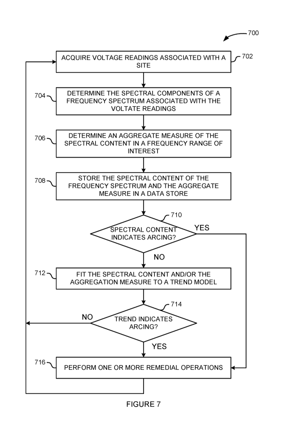
[0067] Figure 7 is a flow diagram of method steps for detecting
electrical arcing in
an electrical system, according to various embodiments. Although the method
steps
are described in conjunction with the systems of Figures 1-6D, persons skilled
in the
art will understand that any system configured to perform the method steps in
any
order falls within the scope of the present invention.
[0068] The method 700 begins at step 702, where a PLC application
executing on
a network communications device 102 acquires voltage readings constituting
waveform data associated with a site 104. The PLC application detects line-to-
line
voltage readings between a first line voltage signal and a second line voltage
signal.
Additionally or alternatively, the PLC application detects readings between a
neutral
signal and either of the line voltage signals. The PLC application obtains the
voltage
readings via power line communications components included in the network
19
CA 03161567 2022-05-12
WO 2021/101869 PCT/US2020/060850
communications device 102. These power line communications components include,
without limitation, a PLC module that further includes a PLC coupler and a PLC
modem. The PLC coupler connects the PLC modem to the line and/or neutral
signals
for communication. The voltage readings at the network communications device
102
are exemplified by Figures 6A-6B. In order to facilitate analysis of the
electrical arcing
signal, the PLC module voltage signal performs an analog-to-digital conversion
to
convert the analog voltage signal into digital samples.
[0069] The PLC module applies a high-pass filter to either the analog
voltage
signal or to the digital samples to remove the fundamental voltage frequency,
typically
50 Hz or 60 Hz. After applying the high-pass filter, only the electrical
arcing signals
and possibly some PLC communications signals remain, thereby further
facilitating
analysis of the electrical arcing signal. The voltage readings at the network
communications device 102 after removing the fundamental voltage frequency are
exemplified by Figure 6C.
[0070] At step 704, the PLC application determines spectral content of a
frequency
spectrum associated with the voltage readings. The PLC may generate the
frequency
spectrum via any technically feasible mechanism, including, without
limitation, fast
Fourier transform (FFT) and discrete Fourier transform (DFT). The spectral
content of
the frequency spectrum is exemplified by Figure 6D.
[0071] At step 706, the PLC application optionally determines an aggregate
measure of the spectral content of the frequency spectrum in a frequency range
of
interest. In general, the frequency range of interest is an operational
frequency range
of the PLC module and is consistent with a frequency range over which
electrical
arcing is detectable. In one example, the frequency range of interest could be
1 kHz
to 1 MHz. In another example, the frequency range of interest could be 100 kHz
to
500 kHz. The aggregated measure could be any technically feasible measure
indicative of an electrical arcing condition, including, without limitation, a
weighted
sum of the spectral content and the area under the curve of the range of
interest. At
step 708, the PLC application stores the spectral content of the frequency
spectrum
and the aggregate measure resulting from the aggregation computation in a data
store, such as data store 340 and/or data store 440.
CA 03161567 2022-05-12
WO 2021/101869 PCT/US2020/060850
[0072] At step 710, the PLC application determines whether the spectral
content is
indicative of an electrical arcing condition. In making this determination,
the PLC
application may use any technically feasible approach. In one example, the PLC
application could determine that the spectral content is indicative of an
electrical
arcing condition if any one or more components of the frequency spectrum
exceed a
predetermined and/or configurable threshold level. In another example, the PLC
application could determine that the spectral content is indicative of an
electrical
arcing condition if the aggregate measure determined in step 706 exceeds a
predetermined and/or configurable threshold level. If the PLC application
determines
that the spectral content is not indicative of an electrical arcing condition,
then the
method 700 proceeds to step 712, where the PLC application fits the results
stored in
step 708 in a data store to a trend model that reflects the behavior of the
voltage
readings, spectral content, and/or aggregate measure associated with the site
104
over time. In some embodiments, the PLC application may fit the stored results
to the
trend model via a linear least squares technique. If the PLC application
determines
that the trend of the spectral content and/or aggregate measure is indicative
of an
electrical arcing condition, then the method 700 proceeds to step 716, where
the PLC
application performs one or more remedial operations.
[0073] At step 714, the PLC application determines whether the trend of
the
voltage readings is indicative of an electrical arcing condition or an
increase in
electrical arcing over a duration of time. In making this determination, the
PLC
application may use any technically feasible approach. In one example, the PLC
application could determine that the trend model of the voltage readings is
indicative
of an electrical arcing condition if the slope of the trend model exceeds a
predetermined and/or configurable threshold level, such as 1.0, 1.1, 1.2, and
so on.
Additionally or alternatively, the PLC application could determine that the
trend of the
voltage readings is indicative of an electrical arcing condition if the slope
of the
trend exceeds a predetermined and/or configurable trend threshold level and
one or
more components of the frequency spectrum exceed a predetermined and/or
configurable frequency spectral threshold.
[0074] If, at step 714, the PLC application determines that the trend is
not
indicative of an electrical arcing condition, then the method 700 proceeds to
step 702,
described above. If, on the other hand, the PLC application determines that
the trend
21
CA 03161567 2022-05-12
WO 2021/101869 PCT/US2020/060850
is indicative of an electrical arcing condition, then the method 700 proceeds
to step
716, where the PLC application performs one or more remedial operations.
[0075] At step 716, the one or more remedial operations are based on at
least one
of the spectral content of the frequency spectrum and a trend analysis of the
frequency spectrum, which are further based on the voltage readings. In one
example, the PLC application could report the potential electrical arcing
condition to
the edge device 108, to a central server in a central office 106, and/or to
one or
neighboring network communications devices 102. In another example, the PLC
application could transmit a portion of the voltage readings after the high-
pass filter to
the edge device 108, to a central server in a central office 106, and/or to
one or
neighboring network communications devices 102. In yet another example, the
PLC
application could transmit the spectral content of the frequency spectrum
and/or the
aggregation measure to the edge device 108, to a central server in a central
office
106, and/or to one or neighboring network communications devices 102. In yet
another example, the PLC application could generate an alert to a user
associated
with the site 104 to inform the user of the electrical arcing condition. The
PLC
application could generate the alert via any one or more technically feasible
mechanisms, including, without limitation, illuminating an indicator light on
the network
communications device 102, generating an audio signal such as a siren,
generating a
computer simulated voice signal announcing the electrical arcing condition,
transmitting a text message to the user, sending an email to the user, causing
a smart
speaker to inform the user of the electrical arcing condition, or transmitting
an alert
message to a smart watch. In yet another example, the PLC application could
disconnect the electrical power to the site 104 to reduce or eliminate the
likelihood of
fire. After the PLC application performs the one or more remedial operations,
the
method 700 proceeds to step 702, described above.
[0076] As described herein, the PLC application and PLC module perform
electrical arcing analysis concurrently with PLC communications transmitting
and
receiving. Even so, in some embodiments, the method 700 may be suspected
during
PLC communications because the high-frequency complements of the PLC
communications may interfere with the voltage components read during step 702
over
the frequencies being analyzed and, as a result, may interfere with electrical
arcing
detection. Therefore, the PLC application and PLC module may temporarily
suspend
22
CA 03161567 2022-05-12
WO 2021/101869 PCT/US2020/060850
electrical arcing analysis when receiving and/or sending a PLC message. In
that
regard, when performing electrical arcing analysis, the PLC application 364
may
detect PLC communications, such as a request to receive and/or transmit a
message
via the PLC modem 366. In such cases, the PLC application 364 suspends
electrical
-- arcing analysis prior to completion, switches to PLC communications mode,
and
processes the PLC communications. After processing the PLC request, the PLC
application 364 resumes the electrical arcing analysis mode. In this manner,
the PLC
application 364 performs electrical arcing analysis with little to no
disruption of PLC
communications.
[0077] In some embodiments, the PLC application 364 and the PLC module 368
may detect electrical arcing occurring on the power utility side, external to
the site
104. Consequently, an electrical arcing condition occurring at one site 104
may be
detected by multiple network communications devices 102 in addition to the
network
communications device 102 at the site 104. In such embodiments, the network
-- communications devices 102 may exchange data associated with the electrical
arcing
condition. For example, if four network communications devices 102 detect a
voltage
anomaly, the four meters may exchange the magnitude of the voltage anomaly.
The
network communications device 102 that observed the highest magnitude of the
voltage anomaly is likely associated with the site 104 where the electrical
arc
-- occurred. In this manner, each of the network communications devices 102
may
differentiate electrical arcing conditions occurring within the corresponding
site 104
from electrical arcing conditions occurring at other sites 104.
[0078] In sum, a network communications device with PLC capability is
configured
to perform electrical arcing detection. The network communications device
acquires
-- voltage readings in the form of waveform data via the PLC transceiver for
own or
more circuits associated with the network communications device. The PLC
application analyzes the voltage readings over time to detect electrical
arcing
conditions. During the analysis, the PLC application correlates and compares
these
voltage readings over an extended period of time to look for trends indicating
that an
-- electrical arcing condition is developing in one or more circuits.
[0079] At least one technical advantage of the disclosed techniques
relative to the
prior art is that electrical arcing can be detected for an entire site, such
as a
household or other building structure, from a single location. Thus, with the
disclosed
23
CA 03161567 2022-05-12
WO 2021/101869 PCT/US2020/060850
techniques, a residence or other building structure can be protected from
electrical
arcing without having to replace all circuit breakers within the structure
with AFCI-type
circuit breakers. Another technical advantage relative to the prior art is
that, with the
disclosed techniques, is that, by analyzing a frequency spectrum derived from
voltage
readings over sequential time periods, electrical arcing conditions that
develop slowly
over time can be detected. By contrast, conventional current-based arc-fault
circuit
interrupters only detect only sudden, high-magnitude electrical arcing, are
unable to
analyze such long-term electrical arcing conditions. These technical
advantages
represent one or more technological advancements over prior art approaches.
lo [0080] 1. In some embodiments, a computer-implemented method for
detecting
electrical arcing in an electrical system comprises: acquiring, via a first
power line
communications (PLC) modem, first voltage readings associated with an
electrical
circuit; performing one or more operations based on the first voltage readings
to
determine that an electrical arcing condition is present within the electrical
circuit; and
performing a remedial operation in response to determining that the electrical
arcing
condition is present.
[0081] 2. The computer-implemented method according to clause 1, wherein
the
one or more operations comprise detecting that a plurality of voltage values
included
in the first voltage readings has at least one high-frequency signal
component.
[0082] 3. The computer-implemented method according to clause 1 or clause
2,
wherein the one or more operations comprise: generating a frequency spectrum
from
the first voltage readings; and determining that a spectral component of the
frequency
spectrum exceeds a threshold level.
[0083] 4. The computer-implemented method according to any of clauses 1-
3,
wherein the one or more operations further comprise: generating an aggregate
measure of spectral content of the frequency spectrum in a frequency range of
interest; and determining that the aggregate measure exceeds a threshold
level.
[0084] 5. The computer-implemented method according to any of clauses 1-
4,
wherein the one or more operations further comprise: fitting at least one of
the
spectral content or the aggregate measure to a trend model that reflects
behavior of
the at least one of the spectral content or the aggregate measure over a
period of
24
CA 03161567 2022-05-12
WO 2021/101869 PCT/US2020/060850
time; and determining, based on the trend model, that a trend of the at least
one of
the spectral content or the aggregate measure is indicative of an electrical
arcing
condition.
[0085] 6. The computer-implemented method according to any of clauses 1-
5,
wherein the first voltage reading is associated with a first site, and wherein
the one or
more operations comprise: receiving, via a network communications device,
second
voltage readings associated with a second site; determining that the second
voltage
readings correspond to the first voltage readings; comparing a first value
included in
the first voltage readings with a second value included in the second voltage
readings; determining that the first value exceeds the second value; and in
response,
determining that the electrical arcing condition is associated with the first
site and not
with the second site.
[0086] 7. The computer-implemented method according to any of clauses 1-
6,
further comprising: identifying, based on a load pattern, a load that is
operating during
the electrical arcing condition; and associating the load with the electrical
arcing
condition.
[0087] 8. The computer-implemented method according to any of clauses 1-
7,
further comprising: detecting communications via the PLC modem; suspending the
one or more operations to determine that an electrical arcing condition is
present;
processing the communications with the PLC modem; and resuming the one or more
operations to determine that an electrical arcing condition is present.
[0088] 9. The computer-implemented method according to any of clauses 1-
8,
wherein the remedial operation comprises disconnecting the electrical circuit
from an
electrical utility via a service disconnect.
[0089] 10. The computer-implemented method according to any of clauses 1-9,
wherein the remedial operation comprises transmitting the first voltage
readings to a
central office, an edge device, or another network communications device.
[0090] 11. The computer-implemented method according to any of clauses 1-
10,
wherein the remedial operation comprises transmitting a first message to a
central
office, an edge device, or another network communications device indicating
that the
electrical arcing condition has been detected.
CA 03161567 2022-05-12
WO 2021/101869 PCT/US2020/060850
[0091] 12. The computer-implemented method according to any of clauses 1-
11,
wherein the remedial operation comprises generating an alert to inform a user
of the
electrical arcing condition.
[0092] 13. In some embodiments, one or more non-transitory computer-
readable
media store program instructions that, when executed by one or more
processors,
causes the one or more processors to perform the steps of: acquiring first
voltage
readings associated with an electrical circuit; performing, via a first power
line
communications (PLC) transceiver, one or more operations based on the first
voltage
readings to determine that an electrical arcing condition is present within
the electrical
circuit; and performing a remedial operation in response to determining that
the
electrical arcing condition is present.
[0093] 14. The one or more non-transitory computer-readable media
according to
clause 13, wherein the one or more operations comprise detecting that a
plurality of
voltage values included in the first voltage readings has at least one high-
frequency
signal component.
[0094] 15. The one or more non-transitory computer-readable media
according to
clause 13 or clause 14, wherein the one or more operations comprise:
generating a
frequency spectrum from the first voltage readings; and determining that a
spectral
component of the frequency spectrum exceeds a threshold level.
[0095] 16. The one or more non-transitory computer-readable media according
to
any of clauses 13-15, wherein the one or more operations further comprise:
generating an aggregate measure of spectral content of the frequency spectrum
in a
frequency range of interest; and determining that the aggregate measure
exceeds a
threshold level.
[0096] 17. The one or more non-transitory computer-readable media according
to
any of clauses 13-16, wherein the one or more operations further comprise:
fitting at
least one of the spectral content or the aggregate measure to a trend model
that
reflects behavior of the at least one of the spectral content or the aggregate
measure
over a period of time; and determining, based on the trend model, that a trend
of the
at least one of the spectral content or the aggregate measure is indicative of
an
electrical arcing condition.
26
CA 03161567 2022-05-12
WO 2021/101869 PCT/US2020/060850
[0097] 18. The one or more non-transitory computer-readable media
according to
any of clauses 13-17, wherein the first voltage readings are associated with a
first
site, and wherein the one or more operations comprise: receiving, via a
network
communications device, second voltage readings associated with a second site;
determining that the second voltage readings correspond to the first voltage
readings;
comparing a first value included in the first voltage readings with a second
value
included in the second voltage readings; determining that the first value
exceeds the
second value; and in response, determining that the electrical arcing
condition is
associated with the first site and not with the second site.
lo [0098] 19. The one or more non-transitory computer-readable media
according to
any of clauses 13-18, wherein the steps further comprise: identifying, based
on a load
pattern, a load that is operating during the electrical arcing condition; and
associating
the load with the electrical arcing condition.
[0099] 20. In some embodiments, a system comprises: a memory that
includes
instructions, and a processor that is coupled to the memory and, when
executing the
instructions, is configured to: acquire, via a power line communications (PLC)
device,
first voltage readings associated with an electrical circuit; perform one or
more
operations based on the first voltage readings to determine that an electrical
arcing
condition is present within the electrical circuit; and perform a remedial
operation in
response to determining that the electrical arcing condition is present.
[moo] Any and all combinations of any of the claim elements recited in
any of the
claims and/or any elements described in this application, in any fashion, fall
within the
contemplated scope of the present invention and protection.
[0101] The descriptions of the various embodiments have been presented
for
purposes of illustration, but are not intended to be exhaustive or limited to
the
embodiments disclosed. Many modifications and variations will be apparent to
those
of ordinary skill in the art without departing from the scope and spirit of
the described
embodiments.
[0102] Aspects of the present embodiments may be embodied as a system,
method or computer program product. Accordingly, aspects of the present
disclosure
may take the form of an entirely hardware embodiment, an entirely software
27
CA 03161567 2022-05-12
WO 2021/101869
PCT/US2020/060850
embodiment (including firmware, resident software, micro-code, etc.) or an
embodiment combining software and hardware aspects that may all generally be
referred to herein as a "module" or "system." Furthermore, aspects of the
present
disclosure may take the form of a computer program product embodied in one or
more computer readable medium(s) having computer readable program code
embodied thereon.
[0103]
Any combination of one or more computer readable medium(s) may be
utilized. The computer readable medium may be a computer readable signal
medium
or a computer readable storage medium. A computer readable storage medium may
be, for example, but not limited to, an electronic, magnetic, optical,
electromagnetic,
infrared, or semiconductor system, apparatus, or device, or any suitable
combination
of the foregoing. More specific examples (a non-exhaustive list) of the
computer
readable storage medium would include the following: an electrical connection
having
one or more wires, a portable computer diskette, a hard disk, a random access
memory (RAM), a read-only memory (ROM), an erasable programmable read-only
memory (EPROM or Flash memory), an optical fiber, a portable compact disc read-
only memory (CD-ROM), an optical storage device, a magnetic storage device, or
any
suitable combination of the foregoing. In the context of this document, a
computer
readable storage medium may be any tangible medium that can contain, or store
a
program for use by or in connection with an instruction execution system,
apparatus,
or device.
[0104]
Aspects of the present disclosure are described above with reference to
flowchart illustrations and/or block diagrams of methods, apparatus (systems)
and
computer program products according to embodiments of the disclosure. It will
be
understood that each block of the flowchart illustrations and/or block
diagrams, and
combinations of blocks in the flowchart illustrations and/or block diagrams,
can be
implemented by computer program instructions. These computer program
instructions may be provided to a processor of a general purpose computer,
special
purpose computer, or other programmable data processing apparatus to produce a
machine. The instructions, when executed via the processor of the computer or
other
programmable data processing apparatus, enable the implementation of the
functions/acts specified in the flowchart and/or block diagram block or
blocks. Such
processors may be, without limitation, general purpose processors, special-
purpose
28
CA 03161567 2022-05-12
WO 2021/101869 PCT/US2020/060850
processors, application-specific processors, or field-programmable gate
arrays.
[0105] The flowchart and block diagrams in the figures illustrate the
architecture,
functionality, and operation of possible implementations of systems, methods
and
computer program products according to various embodiments of the present
invention of the present disclosure. In this regard, each block in the
flowchart or block
diagrams may represent a module, segment, or portion of code, which comprises
one
or more executable instructions for implementing the specified logical
function(s). It
should also be noted that, in some alternative implementations, the functions
noted in
the block may occur out of the order noted in the figures. For example, two
blocks
shown in succession may, in fact, be executed substantially concurrently, or
the
blocks may sometimes be executed in the reverse order, depending upon the
functionality involved. It will also be noted that each block of the block
diagrams
and/or flowchart illustration, and combinations of blocks in the block
diagrams and/or
flowchart illustration, can be implemented by special purpose hardware-based
systems that perform the specified functions or acts, or combinations of
special
purpose hardware and computer instructions.
[0106] While the preceding is directed to embodiments of the present
disclosure,
other and further embodiments of the disclosure may be devised without
departing
from the basic scope thereof, and the scope thereof is determined by the
claims that
follow.
29